

J. Cent. South Univ. (2020) 27: 3875-3887
DOI: https://doi.org/10.1007/s11771-020-4470-3

A numerical study of fracture initiation under different loads during hydraulic fracturing
TANG Shi-bin(������)1, DONG Zhuo(��)1, WANG Jia-xu(������)1, MAHMOOD Ahmad2
1. State Key Laboratory of Coastal and Offshore Engineering, Dalian University of Technology, Dalian 116024, China;
2. Department of Civil Engineering, University of Engineering and Technology Peshawar (Bannu Campus), Bannu 28100, Pakistan
 Central South University Press and Springer-Verlag GmbH Germany, part of Springer Nature 2020
Abstract:
The fracture initiation behavior for hydraulic fracturing treatments highlighted the necessity of proposing fracture criteria that precisely predict the fracture initiation type and location during the hydraulic fracturing process. In the present study, a Mohr-Coulomb criterion with a tensile cut-off is incorporated into the finite element code to determine the fracture initiation type and location during the hydraulic fracturing process. This fracture criterion considers the effect of fracture inclination angle, the internal friction angle and the loading conditions on the distribution of stress field around the fracture tip. The results indicate that the internal friction angle resists the shear fracture initiation. Moreover, as the internal friction angle increases, greater external loads are required to maintain the hydraulic fracture extension. Due to the increased pressure of the injected water, the tensile fracture ultimately determines the fracture initiation type. However, the shear fracture preferentially occurs as the stress anisotropy coefficient increases. Both the maximum tensile stress and equivalent maximum shear stress decrease as the stress anisotropy coefficient increases, which indicates that the greater the stress anisotropy coefficient, the higher the external loading required to propagate a new fracture. The numerical results obtained in this paper provide theoretical supports for establishing basis on investigating of the hydraulic fracturing characteristics under different conditions.
Key words:
hydraulic fracturing; internal friction angle; stress anisotropy coefficient; finite element method��
Cite this article as:
TANG Shi-bin, DONG Zhuo, WANG Jia-xu, AHMAD Mahmood. A numerical study of fracture initiation under different loads during hydraulic fracturing [J]. Journal of Central South University, 2020, 27(12): 3875-3887.
DOI:https://dx.doi.org/https://doi.org/10.1007/s11771-020-4470-31 Introduction
Hydraulic fracturing is an effective technology which has been widely used in unconventional development of energy resource including tight gas and oil reservoirs, coal bed methane and enhanced geothermal systems. During the hydraulic fracturing process, high-pressure water is injected into the reservoirs to create a large amount of fractures. The hydraulic fracturing technology has been highly developed during the last decades in North America and recent years in China. However, there are still several other limitations that require further studies.
Understanding of how the injected water pressure extends the pre-existing fractures to form a complex fracture network in the hydraulic fracturing is still underexplored.Many researchers have conducted experiments to investigate the influence of the local in-situ stress field, the pre-existing fracture geometry, the rock strength parameters and the injected water pressure on the hydraulic fracture behaviors [1-6]. However, experimental investigations are usually expensive and time-consuming and have achieved limited results. Therefore, theoretical and numerical methods have been gradually increase to explore the hydraulic fractures initiation behaviors, which make parametric analysis easier compared with experimental studies. There were basic theoretical works on fracture initiation under the combination of injection water pressure and far field stresses. For example, TANG et al [7] proposed a maximum tensile strain criterion, which considers the effect of T-stress on fracture growth. DONG et al [8] and TANG et al [9] proposed a theoretical model, which is based on linear elastic fracture mechanics (LEFM), to study hydraulic fracturing through a single/double radial perforation emanating from a borehole. However, WANG [10] indicated that LEFM theory can reasonably predict hard rock hydraulic fracturing processes, but often fails to accurately predict fracture geometry and propagation pressure in ductile and quasi-brittle rocks, hence they developed a hydraulic fracture model combining the cohesive zone method and Mohr-Coulomb flow theory of plasticity. TUNSAKUL et al [11], NING et al [12] and WANG et al [13] investigated the fracture initiation, propagation and coalescence in rocks using the strength criterion and considered the effect of both cohesion and internal friction angle. Recently, the numerical methods based on the strength criterion have emerged as a powerful numerical procedure for the analysis of hydraulic fracturing problems. LI et al [14] used the maximum stress criterion and Mohr-Coulomb theory to analyze the material parameter effects on the hydraulic fracture initiation in a near wellbore region. GONCALVES et al [15] used the finite element code employing the strength criterion proposed by BOBET [16] to study the fracture initiation subjected to internal fluid pressure and vertical stress. However, they ignored the effects of the cohesion and internal friction angle. HUANG et al [17] proposed a 3D model to explore the natural fractures initiation and fracture type prediction in coal reservoir under different in-situ stresses which used a finite element method ANSYS workbench. However, they mainly focused on the compressive and shear fractures initiation while ignoring the effects of the internal friction angle. Moreover, they did not study the tensile fractures initiation behavior. BI et al [18] adopted the general particle dynamics (GPD) model based on the Hoek-Brown strength criterion to simulate the hydraulic fracture initiation, propagation and coalescence, while they ignored the effect of in-situ stress anisotropy coefficient. The numerical model developed by ZHANG et al [19] showed that in-situ stresses have an important influence on the hydraulic fracture initiation behaviors.
In this paper, a Mohr-Coulomb criterion with a tensile cutoff is proposed which relies on the assumption that the crack initiation depends on the local stress relative to the rock strength. In addition, the proposed fracture criterion is implemented into the finite element code (ANSYS) to simulate the hydraulic fracturing behaviors under different fractures geometry and loading conditions. The proposed fracture criterion considering the internal friction angle can predict accurately the types and locations of newly formed fracture (such as tension and shearing fractures). Furthermore, studies have been conducted to investigate the influence of the pre-existing fractures geometry, the injected water pressure, the stress anisotropy coefficient and the rock internal friction angle on hydraulic fracture mechanism. The overall outline of this paper is as follows. Section 2 includes a brief review of the Mohr-Coulomb theory and a description of the tensile and shear fracture criterion that is analyzed in this paper. In Section 3, a verification example with a single-fracture model is reported to prove the applicability of the new theory. In Section 4, the fracture initiation locations obtained from different paths around the fracture tip are studied and compared. In Section 5, the stress field distribution around the crack tip and the fracture initiation location in single- and double-fracture models under different conditions are simulated and studied. In the last section, the conclusions are briefly summarized and listed to quickly review this study.
2 Fracture initiation criterion
The fracture initiation criterion is important for predicting and identifying fracture initiation. The Mohr-Coulomb criterion is the simplest shear fracture criterion that has been developed and extensively used in rock engineering [13, 15, 16], and the maximum tensile stress criterion suitably predicts the tensile fracture. Therefore, the Mohr-Coulomb criterion with a tensile cutoff is combined in this study to balance the advantages of both theories. When the maximum tensile stress at a certain point around the fracture tip reaches the tensile strength of rock, tensile fracture will be triggered to form at this certain point. In addition, when the stress state at a point reaches to the critical state determined by Mohr-Coulomb criterion, shear fracture will occur along the direction at a specific angle (relates to the friction angle ��) to the maximum principle stress. A detailed description of the fracture criterion used in this paper is presented in the following subsections. It should be noted that, according to rock mechanics, the tensile stress and dilatant strain are referred as negative while the compressive stress and contractive strain are referred as positive, which is opposite to the sign in ANSYS [20].
2.1 Tensile fracture
Figure 1 shows the Mohr-Coulomb criterion with tensile cutoff. According to Figure 1, when the tensile stress in the normal direction reaches to the critical tensile strength, tensile fracture initiates and the fracture initiation is at the point of maximum tensile stress, i.e.,
 (1)
(1)
where ��3 is the minimum principle stress, and T0 is the critical tensile strength (a positive value).
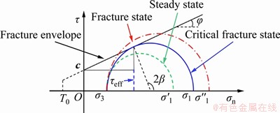
Figure 1 Mohr-Coulomb criterion with a tensile cutoff
When the tensile stresses at each point around the fracture tip (��3-points) are obtained by the finite element code ANSYS, the maximum tensile stress (��t,max) among them can be determined, i.e., ��t,max= max(��3-points). If the maximum tensile stress (��t,max) satisfies Eq. (1), tensile fracture will start at the location of the maximum tensile stress, and the tensile fracture criterion can be given by Eq. (2):
 (2)
(2)
2.2 Shear fracture
The Mohr-Coulomb criterion can be used to determine the shear fracture initiation through the stress state by Eq. (3):
 (3)
(3)
where �� is the shear stress; �ҡ�n is the effective normal stress; c and �� are the cohesion and internal friction angle of rock, respectively.
The criterion can be expressed through the fracture envelope line shown in Figure 1. The green Mohr stress circle under the fracture envelope line indicates that the stress point is in steady state because the shear stress on that does not reach the critical shear strength so that the shearing fracture is not generated. In contrast, the red circle that is above the envelope line denotes the maximum shear stress on the point is larger than the critical shear strength, i.e., the shearing crack occurs. Furthermore, when the Mohr stress circle is tangent to the fracture envelope line (see blue circle), indicating the rock is in limit equilibrium state and the direction of cracking can be given by Eq. (4):
 (4)
(4)
The normal and tangential stresses on the inclined �� plane can be determined by the maximum and minimum principal stress given by Eq. (5) and Eq. (6):
 (5)
(5)
 (6)
(6)
where ��1 and ��3 are the maximum and minimum principal stresses at the same point, respectively.
By substituting Eqs. (5) and (6) into Eq. (3), Eq. (7) is obtained:
 (7)
(7)
By substituting Eq. (4) into Eq. (7), Eq. (8) is obtained:
 (8)
(8)
In other words, if the maximum and minimum principle stresses at a point satisfy Eq. (8), the shear fracture will initiate. Hence, it is important to find the location around the crack tip whose stress states meet Eq. (8). In our method, the stress states including ��1 and ��3 at each point surrounding the fracture tip are calculated by finite element code ANSYS. Then they are substituted to the left side of Eq. (8), i.e.,
 (9)
(9)
Thus, the location of shear cracking is determined by the point of the maximum effective shear stress. It is denoted by a symbol ��eff,max (=max(��eff)) to represent the maximum equivalent shear stress around the fracture tip, and in this way the shear fracture criterion can be given by Eq. (10):
 (10)
(10)
2.3 Fracture initiation types
An extensive experimental program has been conducted on pre-cracked specimens of a brittle rock material to investigate crack propagation and coalescence under compressive loading conditions[21, 22]. The typical types of fracture initiation can be categorized as: tensile fracture, shear fracture and mixed tensile-shear fracture. It should be noted that, according to the above-mentioned fracture criterion, only the fracture initiation behaviors are investigated and the fracture propagation processes are not considered in this study and both the tensile and shear fracture criterion are considered to determine the fracture initiation types in this paper. Equations (1) and (9) show that the fracture criterions only depend on the maximum and minimum principle stresses around the crack tip. The fracture types are determined by the criterion which is satisfied by the stress field around the crack tip. In other words, certain fracture types will be determined when the stress field meets the corresponding criterion equations. According to Eq. (11a), if the tensile fracture criterion is satisfied preferentially, the tensile fracture will start to form. According to Eq. (11b), if the shear fracture criterion is met preferentially, the shear fracture will start to form. Moreover, according to Eq. (11c), the mixed tensile-shear crack will occur when both tension and shearing criteria are fulfilled.
 (11a)
(11a)
(11b)
 (11c)
(11c)
What��s more, the ratio method is proposed to determine which fracture criterions will be satisfied preferentially. The ratio of the maximum equivalent shear stress to the maximum tensile stress is expressed by Eq. (12):
 (12)
(12)
The critical tensile strength T0, the internal friction angle �� and cohesion c are the rock intrinsic qualities. Hence, the ratio of the cohesion to the critical tensile strength can be defined by Eq. (13):
 (13)
(13)
According to Eq. (13), for a constant cohesion, the smaller the tensile strength, the greater the value of A2. Therefore, the tensile fracture type is more likely to occur. When A1>A2, the maximum equivalent shear stress will first meet the cohesion as the external loading increases and the shear fracture type will first appear. When A1<>2, the maximum tensile stress will first meet the tensile strength with the increasing loading conditions and the tensile fracture type will first occur. Moreover, the mixed tensile-shear fracture type will occur when A1 = A2.
3 A validation example
To validate the fracture criterion proposed in this paper, the authors built a 2D numerical model with the same condition as the laboratory test performed by WONG et al [23]. The specimen sizes are fixed as h=152 mm and w=76 mm; the pre-existing open fracture length is 2a=12.7 mm and the aperture of the fracture is 1.3 mm as shown in Figure 2(a). Elastic modulus E=5960 MPa, Poisson ratio ��=0.15 and the internal friction angle is constantly assumed to 25��. In addition, the loading case in this subsection is uniaxial compression (��v=2 MPa). The material is assumed to linearly elastic, which means that only elastic modulus and Poisson ratio were introduced in ANSYS. Hence, only the elastic deformation was considered to analyze the stress distribution around the pre-existing fracture tip. Figure 2(b) displays a typical mesh pattern used for simulating single-fracture model. The pre-existing fracture tip is considered as semi-circular shape. The dense mesh grid is used around the fracture tip because of the stress concentration in that region. The finite elements considered in this analysis consist of 4-node linear quadrilateral element.
The numerical result of stresses distribution around the fracture tip for the case of ��=30�� is plotted in Figure 3. The negative values mean the tensile stress around the fracture tip, while the positive values mean the compressive stress as shown in Figure 3(a). It shows that each cracking tip has a region of maximum tensile stress (Region 1 for the upper right fracture tip and Region 2 for another tip). The distribution of equivalent shear stress (��eff) around the fracture tip calculated by Eq. (9) is also shown in Figure 3(b). It indicates that each cracking tip has two regions of maximum equivalent shear stress (i.e., Region 3 and Region 4 for the upper right fracture tip and Region 5 and Region 6 for the other tip). Since the stress distributions of the two fracture tips shown in Figure 3 are symmetrical, the authors only analyzed the mechanical behavior of the upper right fracture tip. Figures 3(a) and (b) show that the maximum equivalent shear stresses in Region 3 are almost overlapped with the location of the maximum tensile stress at Region 1. Hence, the mixed tensile-shear fracture type is likely to occur in this region if the stress states stratify Eq. 11(c). The uniaxial compressive experiments are performed by WONG et al [23], which indicates that the shear fracture initiates in Region 3 at first and then followed by tensile fracture propagation as shown in Figure 3(c). In addition, the present numerical results also consistent with the first fracture type (mixed tensile-shear crack) obtained by WONG et al [24] as shown in Figure 3(d). When the stress state reaches the rock tensile strength primarily in Regions 1 or 3, the tensile fracture type preferentially appears, which is consistent with the second fracture initiation type shown in Figure 3(d). Moreover, as shown in Figure 3(b), the maximum equivalent shear stress shown in Region 4 or 5 is also likely to cause shear fracture type to appear, which is consistent with the experimental results shown in Figure 3(d) (the third crack type).
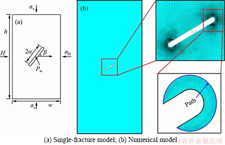
Figure 2 Model geometry and finite element numerical model:
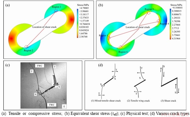
Figure 3 Stress distribution around fracture tip (��=30��) and physical test:
Additionally, the small errors are caused by the simplification of the experimental conditions and the ignorance of the heterogeneity of the rock material while the numerical results well explain the fracture initiation types observed by experiments. Hence, the fracture criterion proposed in this study is suitable for investigating the stress distribution characteristics around the fracture tip and the fracture initiation types under different loading conditions.
4 Determining stress path
According to the fracture criterion proposed in this paper, the fracture initiation location depends on the accurate calculation of the maximum and minimum principal stresses around the fracture tip. GONCALVES et al [25] studied the effect of three different paths around the fracture tip on the newly formed fracture initiation location (Figure 4), i.e., path 1 is the fracture surface itself; path 2 is a circular with the radius twice of the fracture tip and with the same center point; and path 3 is a semicircular surface which has the same location for path 2. There are many numerical studies using the path 2 and path 3 to investigate the fracture initiation location under different loading conditions[15, 17], while in this study, path 1 is used to determine the fracture initiation behaviors, and different results have been obtained. Path 1 varies with �� counterclockwise in the range of -150��to 150��.
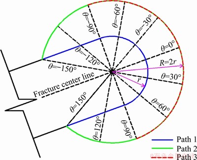
Figure 4 Circular path around fracture tip
With reference to the numerical results obtained by LI et al [26], who investigated the fracture initiation location under different fracture inclination angles. The comparison of the fracture initiation locations between the results of the present numerical study and that of LI et al [26] are illustrated in the sketches in Figure 5. Note that the fracture initiation locations triggered by the maximum tensile stress and equivalent maximum shear stress are marked and reported as a solid circle (tensile fracture type) and open circle (shear fracture type), respectively. As shown in Figure 5, only the fracture initiation location obtained from path 1 is consistent with the numerical results proposed by LI et al [26]. Taking the case of ��=35�� as an example, in the results obtain from path 2, the tensile fracture type appears at ��T=-150�� and the shear fracture type appears at the upper fracture surface near the fracture centerline. These results are not consistent with the numerical results obtained from LI et al [26]. That the two numerical results are highly fitting indicates path 1 can be regarded as acceptable model predicting the location of fractures. Consequently, in the following subsection, path 1 is used to investigate the effect of various parameters on the hydraulic fracture initiation behaviors.
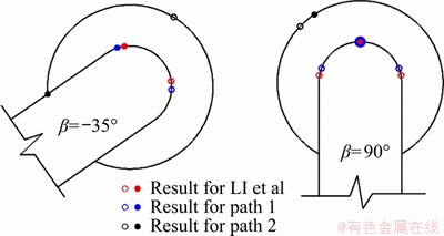
Figure 5 Tensile (solid circle) and shear (open circle) fracture initiation location for different fracture inclination angles
5 Results
The numerical results of single-fracture and double-fracture models are presented in this section. Firstly, parameters including the fracture inclination angle, the injected water pressure and stress anisotropy coefficient are introduced to study the fracture initiation types and location. Secondly, the tensile and shear fracture behaviors are investigated under different injection water pressures for double-fracture model by the above- mentioned path 1. Finally, the numerical conclusions can provide a better understanding of the problem and improve the hydraulic fracturing treatments.
5.1 Single-fracture model
5.1.1 Effect of fracture inclination angle
The numerical model geometry and material properties are configured as the same as those descripted in Section 3, then the effects of the fracture inclination angle and the internal friction angle on the fracture initiation behavior under uniaxial compressive loading condition (��v=2 MPa) are explored. The maximum and minimum principal stresses are directly obtained from the ANSYS output along the path 1. In addition, in this study, the stress state plotted along path 1 was calculated by about 200 points and compared with the results of Refs. [14, 17, 24], which was calculated by fewer points Refs. [15, 18, 25]. Thus, the results obtained from us will more accurately predict the starting point of fractures.
Figure 6(a) reflects the effect of the fracture inclination angle on the maximum tensile stress (��t, max). This indicates that the absolute values of maximum tensile stress first increase with the inclination angle change (0��ܦ�<45��), and reach a maximum value at ��=45�� and gradually decline when �� ranges in 45��<�¡�90��. The relationship between the fracture inclination angles and the maximum tensile stress indicates that the external loading decreases first, and then increases when ��>45��. This conclusion has been demonstrated by the experimental results obtained from LEE et al [27], which indicated that with the increase of fracture inclination angles, the magnitude of crack initiation stress decreases first and then increases.
The effects of the internal friction angle on the maximum shear stress and the shear fracture initiation location are shown in Figure 6(b). It can be observed from Figure 6(b) that for different internal friction angles, the maximum shear stress gradually decreases with increasing fracture inclination angle. This conclusion demonstrates that the external loading required to form shear fracture will increase with the increasing fracture inclination angles. In addition, the maximum shear stresses decrease as the internal friction angle goes up, which indicates that larger external loads are required for shearing crack as the internal friction angle increases. As illustrated in Figure 6(b), the shear fracture initiation locations (��S) are almost the same when the internal friction angles equal to 0�� and 10��. Hence, different internal friction angles slightly affect the initiation locations of shearing cracks but not significantly.
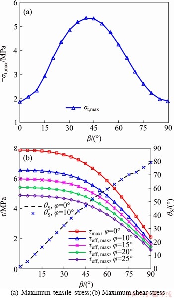
Figure 6 Variations of highest stresses with changes of fracture inclination angles:
Figure 6(b) indicates that the internal friction angle significantly affects the maximum shear stress. Thus, according to Section 2.3, different A1 values can be obtained under different internal friction angles to investigate the cause of fracture. Moreover, according to Eq. (12) and Eq. (13), the type of fracture onset also depends on the normalized parameter A2. The values of A2 are constant when the material properties, the critical tensile strength (��t) and cohesion (c) are defined. In general, the cohesion is larger than the critical tensile strength. For example, the cohesion and critical tensile strength of shale are 2.5-10 MPa and 3.0-30 MPa, respectively; and the internal friction angle is 5��-30��. Hence, three values of A2 are used to investigate its influences on the fracture initiation types and location: A2=1.0, 1.25 and 2.0.
According to Eqs. (12) and (13), when the relationship between parameters A1 and A2 is obtained, the priorities of tensile fracture and shear fracture can be determined. Figure 7 indicates that the value of A1 decreases as the internal friction angle increases. Hence, internal friction angle is an important factor for the fracture initiation types. In addition, for a fixed value of A2, with the growing internal friction angle, the region where shear fracture occurred will narrow while the region where tensile fracture occurred will expand. This conclusion indicates that the internal friction angle inhibits the development of shear fracture. For a fixed value of internal friction angle, with the decreasing parameters A2 (i.e., the increase of tensile strength), the region where shear fracture occurs expands while the region where tensile fracture occurs shrinks. It should be noted that, in any case, the mixed tensile-shear fracture will occur when A1=A2.
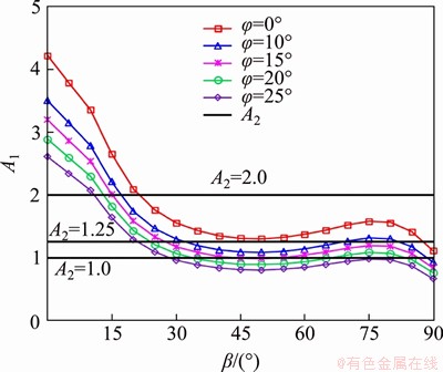
Figure 7 Relation curves between parameters A1 and A2 under different fracture inclination angles
Figure 8 illustrates the relation curves between the corresponding fracture initiation angle and fracture inclination angle under different internal friction angles. The value of parameter A2 is assumed as 1.25. For the condition of ��=15��, when the fracture inclination angle varies from 0�� to 30��, the shear fracture preferentially occurs; the fracture initiation angle is always positive which means the shear fracture always occurs at the lower fracture surface. However, the tensile fracture type will preferentially appear when ��>30��. The tensile fracture always starts at the upper fracture surface and it will gradually approach to the near of the fracture center line as the fracture inclination angle increases. However, for the condition ��=10�� and ��>30��, the shear fracture type will preferentially appear at location near ��=75��. According to the numerical results presented above, it reveals that the internal friction angle plays an important role in the study of different fracture initiation types.
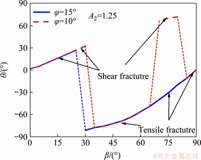
Figure 8 Relation curves between the corresponding fracture initiation angles and fracture inclination angles under different internal friction angles
5.1.2 Effect of injection water pressure
In hydraulic fracturing engineering, the stress state around the fracture varies with the change of the injected water pressure changing, which eventually affects the cracking behaviors of hydraulic fracture. Therefore, the design of hydraulic fracturing requires accurate estimation of water injection pressure to optimize the fracture propagation path. In this section, the effects of the injection water pressure on the fracture type and initiation location are explored. Note that the vertical load remains constant (��v=2 MPa). The injection water pressure Pw is applied along the surface of the pre-existing fractures and the ratio of the injection water pressure to the vertical load is defined as k1=Pw/��v, ranging from 0 to 2.0.
Figure 9 illustrates the results of A1 under different injection water pressure and the values of A2 is assumed as 1.0. Figure 9 indicates that the values of A1 decreases as k1 increases from 0 to 0.5, while its values have almost no effect on the injection water pressure when k1 ��0.5. This indicates that the shear fracture type only appears when the injection water pressure is smaller. What��s more, the increase of injected water pressure has a positive effect on accelerating the tensile fracture extension.
The variation of the highest stresses and corresponding fracture initiation angle under different injection water pressure is shown in Figure 10. It indicates that both the values of the maximum tensile stress and the equivalent maximum shear stress increase as the injection water pressure grows. These results indicate that the hydraulic fracture initiation becomes easier under higher injection water pressure. However, if the injection water pressure is too high, other strata will break down resulting in water leakage. Hence, a suitable injected water pressure should be considered for the actual hydraulic fracturing treatments. In addition, Figure 10 indicates that the shear fracture initiation location occurs in the lower fracture surface. But the tensile fracture initiation location will occur in the upper fracture surface as the injected water pressure increases. It can also be found from Figure 10 that the tensile fracture region is larger than the shear fracture region. It is because the resistance of rock to tensile failure is weak. Thus, even though a few shear fractures were generated, tensile fractures type were dominant in all cases as expected from this result. This conclusion is consistent with the classical theory which believes the hydraulic fracture is formed by tensile fractures [28].
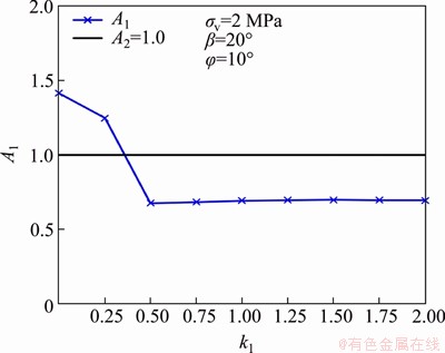
Figure 9 Relation curves between parameter A1 and A2 under different injection water pressures
5.1.3 Effect of stress anisotropy coefficient
In the present study, different in-situ stress loading conditions are obtained by varying the stress anisotropy coefficient which is defined as the ratio of the horizontal loads to the vertical loads and denoted by the k=��H/��v, as shown in Figure 2(a). Note that the vertical load remains constant (��v=2 MPa) and the different values of the stress anisotropy coefficient are obtained by changing the horizontal loads. Expect for the stress anisotropy coefficient, all the other parameters in the figure labels remain constant, as shown in Figure 11.
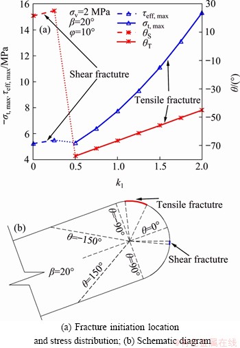
Figure 10 Variations of highest stresses and corresponding fracture initiation angle under different injection water pressures:
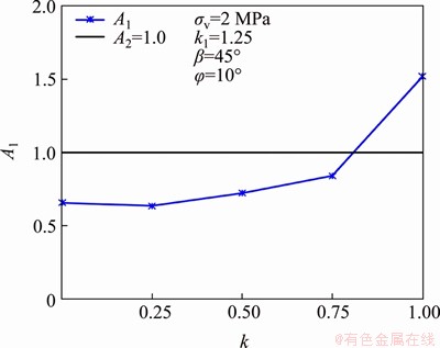
Figure 11 Relation curves between parameter A1 and A2 under different stress anisotropy coefficients
Figure 11 shows the variation of A1 under different stress anisotropy coefficients. The results clearly show that the values of A1 increase gradually with the increment of the stress anisotropy coefficient. It also reveals that the newly formed fracture initiation type changes progressively from tensile fracture to shear fracture as the stress anisotropy coefficient increases. This conclusion indicates that the lateral stress has an inhibition on the tensile fracture type, and the higher the lateral stress, the stronger the inhibition. Hence, the shear fracture type will appear easier under a higher stress anisotropy coefficient. The variations of the highest stresses and corresponding fracture initiation angle under different stress anisotropy coefficients are plotted in Figure 12. The results show that the highest value of maximum tensile stress and equivalent maximum shear stress both decline gradually as the stress anisotropy coefficient increases. The results indicate that the injection water pressure needs promoting to overcome the effect of stress anisotropy coefficient and then to form the new fracture initiation. In addition, the tensile fracture initiation location occurs in the upper fracture surface, while the shear fracture initiation location occurs at the position near the fracture center line when k=1.0. Based on the conclusions, the variations of stress anisotropy coefficients are one of the important factors that are responsible for different fracture initiation locations.

Figure 12 Variations of the highest stresses and corresponding fracture initiation angle under different stress anisotropy coefficients:
5.2 Double-fracture model
The numerical results of double-fracture model under different injected water pressures are investigated in this section. The size of numerical model and the material properties are from GONCALVES et al [15]. The pre-existing open fracture length is 2a=12.7 mm and the aperture of the fractures is 1.4 mm; elastic modulus E=6000 MPa, Poisson ratio ��=0.28 and the internal friction angle is assumed as 10��; the inclined angles of �� and �� are 30��, as shown in Figure 13. GONCALVES et al [15] studied the fracture initiation behaviors for double-fracture model, while they ignored the effect of internal friction angle. In addition, they use path 2 to investigate the tensile and shear fracture initiation behaviors. However, it can be observed from subsection 5.1.1 that the internal friction angle has significant influence on the fracture type and initiation location. Moreover, the conclusion obtained from Section 4 also indicates that, compared with path 2, the results obtained from path 1 are more accurate to predict the fracture initiation location. Therefore, in the present study, the stress states around the fracture tip are obtained from path 1 and the effects of internal friction angle on the shear fracture initiation location under different internal water pressures are discussed.

Figure 13 Schematic diagram of double-fracture model
The loading cases in this subsection are assumed to be ��v=10 MPa, k=0 and the internal water pressure Pw ranges from 0 to 50 MPa. Figure 14 illustrates the variations of the corresponding fracture initiation angles under different injection water pressures. By analyzing Figure 14(a), the following conclusion can be drawn: the results of GONCALVES da SILVA et al [15] show that the tensile fracture initiation angle rarely changes as k1 increases from 0 to 0.6, because the results obtained from path 2 have a certain error from the actual fracture initiation location. However, the results obtained from path 1 (the present results) can accurately represent the fracture initiation location. The tensile fracture initiation location changes gradually from the upper fracture surface to the vicinity of the fracture center line. The trend of the shear fracture initiation angle obtained from the present research under different internal water pressures is smoother than the result obtained from GONCALVES da SILVA et al [15].
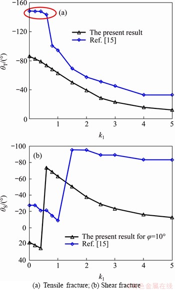
Figure 14 Corresponding fracture initiation angle under different injection water pressures:
Figure 15 shows the tensile and shear fracture initiation locations under different injected water pressures. The shear fracture will appear under the relatively small injected water pressure loading conditions, and the tensile fracture will primarily occur when k1>0.5. Moreover, the tensile fracture initiation location occurs at the upper fracture surface, while the shear fracture initiation location occurs at the lower fracture surface.
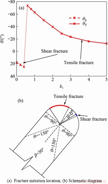
Figure 15 Tensile and shear fracture initiation location under different injection water pressures:
6 Conclusions
Mohr-Coulomb criterion with a tensile cutoff is included in the fracture model to study the effect of the fracture inclination angle, the internal friction angle and the loading conditions on the stress field distribution surrounding the fracture tip. The proposed models illustrate the shortcoming of the classical models with reasonable precision. The following conclusions can be drawn:
1) The fracture initiation locations obtained from the present numerical results are compared to those from the experiments in literatures, and good consistency is shown between them. Moreover, comparisons between the results and the published data indicate that the stress states around the fracture tip obtained from the present stress path are more suitable for investigating the fracture initiation location.
2) The internal friction angle is an important factor affecting the shear stress distribution around the fracture tip. The highest value of shear stress decreases as the internal fraction angle increases, which indicates that larger external loads are required to develop the shear fracture initiation. The shear fracture initiation location is hardly affected by the internal friction angle, whereas the internal friction angle plays an important role in determining the failure type.
3) With the increase of fracture inclination angle and injection water pressure, the fracture initiation types change from shear fracture to tensile fracture. Large stress anisotropy coefficient can suppress tensile fracture and the shear fracture will preferentially occur with the increase of that. In addition, as the cohesion increases or the tensile strength decreases, the possibility of tensile fracture type increases and the shear fracture type becomes weaker.
Contributors
TANG Shi-bin provided the concept and edited the draft of manuscript. DONG Zhuo conducted the numerical modeling and wrote the first draft of the manuscript. WANG Jia-xu and AHMAD Mahmood edited the draft of manuscript.
Conflict of interest
TANG Shi-bin, DONG Zhuo, WANG Jia-xu and AHMAD Mahmood declare that they have no conflict of interest.
References
[1] JIANG Hu, CHEN Mian, ZHANG Guang-qing, JIN Yan, ZHAO Zheng-feng, ZHU Gai-feng. Impact of oriented perforation on hydraulic fracture initiation and propagation [J]. Chinese Journal of Rock Mechanics and Engineering, 2009, 28(7): 1321-1326. (in Chinese)
[2] JIN Xiao-chun, SHAN S. Fracture propagation direction and its application in hydraulic fracturing [C]// SPE Hydraulic Fracturing Technology Conference. The Woodlands, TX: Society of Petroleum Engineers, 2013. DOI: 10.2118/ 163832-MS.
[3] WANG Di, CHEN Mian, JON Yan, TANG Peng, SUN Yi-liu, YUAN Liang, LI Qing. Experimental study of fracture initiation and propagation from a wellbore [C]// 49th US Rock Mechanics/Geomechanics Symposium. San Francisco: American Rock Mechanics Association, 2015.
[4] WANNIARACHCHI W A M, RANJITH P G, PERERA M S A, RATHNAWEERA T D, ZHANG D C, ZHANG C. Investigation of effects of fracturing fluid on hydraulic fracturing and fracture permeability of reservoir rocks: An experimental study using water and foam fracturing [J]. Engineering Fracture Mechanics, 2018, 194: 117-135. DOI: 10.1016/j.engfracmech.2018.03.009.
[5] TANG Shi-bin, WANG Jia-xu, CHEN Pei-zhao. Theoretical and numerical studies of cryogenic fracturing induced by thermal shock for reservoir stimulation [J]. International Journal of Rock Mechanics and Mining Sciences, 2020, 125: 104160. DOI: 10.1016/j.ijrmms.2019.104160.
[6] ZHOU Zhong, YANG Hao, WANG Xiang-can, ZHANG Qi-fang. Fractured rock mass hydraulic fracturing under hydrodynamic and hydrostatic pressure joint action [J]. Journal of Central South University, 2016, 23(10): 2695-2704. DOI: 10.1007/s11771- 016-3331-6.
[7] TANG Shi-bin, ZHANG Heng. Hydraulic fracture prediction theory based on the maximum tangential strain criterion [J]. Chinese Journal of Rock Mechanics and Engineering, 2016, 35(S1): 2710-2719. (in Chinese)
[8] DONG Zhou, TANG Shi-bin, RANJITH P G, LANG Ying-xian. A theoretical model for hydraulic fracturing through a single radial perforation emanating from a borehole [J]. Engineering Fracture Mechanics, 2018. 196: 28-42. DOI: 10.1016/j.engfracmech.2018.04.029.
[9] TANG Shi-bin, DONG Zhou, DUAN Dong, LI Ying-chun. A theoretical model for hydraulic fracturing through two symmetric radial perforations emanating from a borehole [J]. Advances in Materials Science and Engineering, 2019, 1-21. DOI: 10.1155/2019/6094305.
[10] WANG Han-yi. Poro-elasto-plastic modeling of complex hydraulic fracture propagation: Simultaneous multi-fracturing and producing well interference [J]. Acta Mechanica, 2016, 227(2): 507-525. DOI: 10.1007/s00707-015-1455-7.
[11] TUNSAKUL J, JONGPRADIST P, KONGKITKUL W, WONGLERTA, YOUWAI S. Investigation of failure behavior of continuous rock mass around cavern under high internal pressure [J]. Tunnelling and Underground Space Technology, 2013, 34: 110-123. DOI: 10.1016/j.tust.2012.11.004.
[12] NING You-jun, AN Xin-mei, MA Gou-wei. Footwall slope stability analysis with the numerical manifold method [J]. International Journal of Rock Mechanics and Mining Sciences, 2011, 48(6): 964-975. DOI: 10.1016/j.ijrmms. 2011.06.011.
[13] WANG Yun-teng, ZHOU Xiao-ping, XU Xiao. Numerical simulation of propagation and coalescence of flaws in rock materials under compressive loads using the extended non-ordinary state-based peridynamics [J]. Engineering Fracture Mechanics, 2016, 163: 248-273. DOI: 10.1016/ j.engfracmech.2016.06.013.
[14] LI Quan-shu, XING Hui-lin. Numerical analysis of the material parameter effects on the initiation of hydraulic fracture in a near wellbore region [J]. Journal of Natural Gas Science and Engineereing, 2015, 27: 1597-1608. DOI: 10.1016/j.jngse.2015.10.023.
[15] GONCALVES da SILVA B, EINSTEIN H H. Finite Element study of fracture initiation in flaws subject to internal fluid pressure and vertical stress [J]. International Journal of Solids and Structures, 2014, 51(23): 4122-4136. DOI: 10.1016/j.ijsolstr.2014.08.006.
[16] BOBET A. Fracture coalescence in rock materials: Experimental observations and numerical predictions [D]. Massachusetts: Massachusetts Institute of Technology, 1997.
[17] HUANG Sai-peng, LIU Da-meng, YAO Yan-bin, GAN Quan, CAI Yi-yong, XU Lu-lu. Natural fractures initiation and fracture type prediction in coal reservoir under different in-situ stresses during hydraulic fracturing [J]. Journal of Natural Gas Science and Engineereing, 2017, 43: 69-80. DOI: 10.1016/j.jngse. 2017.03.022.
[18] BI J, ZHOU Xiao-ping. A novel numerical algorithm for simulation of initiation, propagation and coalescence of flaws subject to internal fluid pressure and vertical stress in the framework of general particle dynamics [J]. Rock Mechanics and Rock Engineeering, 2017, 50(7): 1833-1849. DOI: 10.1007/s00603-017-1204-4.
[19] ZHANG Yu-shuai, ZHANG Jin-cai. Lithology-dependent minimum horizontal stress and in-situ stress estimate [J]. Tectonophysics, 2017, 703: 1-8. DOI: 10.1016/j.tecto. 2017.03.002.
[20] ANSYS Inc. Theory Reference [M]. ANSYS Inc, 2013.
[21] PARK C H, BOBET A. Crack initiation, propagation and coalescence from frictional flaws in uniaxial compression [J]. Engineering Fracture Mechanics, 2010, 77(14): 2727-2748. DOI: 10.1016/j.engfracmech.2010.06.027.
[22] YANG Sheng-qi, JING Hong-wen. Strength failure and crack coalescence behavior of brittle sandstone samples containing a single fissure under uniaxial compression [J]. International Journal of Fracture, 2010, 168(2): 227-250. DOI: 10.1007/s10704-010-9576-4.
[23] WONG L N Y, EINSTEIN H. Fracturing behavior of prismatic specimens containing single flaws [C]// The 41st US Symposium on Rock Mechanics (USRMS): American Rock Mechanics Association, 2006.
[24] WONG L N Y, EINSTEIN H H. Crack coalescence in molded gypsum and carrara marble: Part 1. Macroscopic observations and interpretation [J]. Rock Mechanics and Rock Engineering, 2008, 42(3): 475-511. DOI: 10.1007/ s00603-008-0003-3.
[25] GONCALVES da SILVA B. Modeling of crack initiation, propagation and coalescence in rocks [D]. Massachusetts: Massachusetts Institute of Technology, 2009.
[26] LI Huang-qiang, WONG L N Y. Influence of flaw inclination angle and loading condition on crack initiation and propagation [J]. International Journal of Solids and Structures, 2012, 49(18): 2482-2499. DOI: 10.1016/ j.ijsolstr.2012.05.012.
[27] LEE H, JEON S. An experimental and numerical study of fracture coalescence in pre-cracked specimens under uniaxial compression[J]. International Journal of Solids and Structures, 2011, 48(6): 979-999. DOI: 10.1016/ j.ijsolstr.2010.12.001.
[28] YEW C H, WENG Xiao-wei. Mechanics of hydraulic fracturing [M]. Houston: Gulf Professional Publishing, 2015.
(Edited by HE Yun-bin)
���ĵ���
��ͬ��������������ˮ���ѷ��������Ե���ֵģ���о�
ժҪ��ˮ���ѷ���������Զ�ˮ��ѹ�ѹ��̵�˳��ʵʩ������Ҫ����ˣ���Ҫ���ȷԤ��ˮ���ѷ��������ͺ�λ�õĶ������ڱ��о��У�����������ضϵ�Ħ��-��������������Ԫ�����У�����ȷ��ˮ���ѷ���������ͺ�λ�á��ö����������ѷ���ǡ���ʯ��Ħ���Ǻ��غ��������ѷ���Ӧ�����ֲ���Ӱ�졣�о������������Ħ�����ܼ������ж��ѷ����Ŀ��ܡ����⣬������Ħ���ǵ����ӣ���Ҫ������ⲿ�غ���ʹˮ���ѷ���չ������עˮѹ�������������ѷ��������վ�����ˮ���ѷ���������͡�������Ӧ��������������Ȳ��������ѷ����͡������Ӧ���͵�Ч����Ӧ��������Ӧ������������С��˵��Ӧ����Խ���ѷ���չ��������غ�Խ���ĵ���ֵ������Ϊ�о���ͬ������ˮ���ѷ����������չ�����ṩ���������ݡ�
�ؼ��ʣ�ˮ��ѹ�ѣ���Ħ���ǣ�Ӧ�������Ԫ����
Foundation item: Project(2017YFC1503102) supported by the National Key Research and Development Program; Projects(51874065, U1903112) supported by the National Natural Science Foundation of China
Received date: 2020-04-10; Accepted date: 2020-09-14
Corresponding author: TANG Shi-bin, PhD, Associate Professor; E-mail: tang_shibin@dlut.edu.cn; ORCID: https://orcid.org/ 0000-0002- 5033-0548
Abstract: The fracture initiation behavior for hydraulic fracturing treatments highlighted the necessity of proposing fracture criteria that precisely predict the fracture initiation type and location during the hydraulic fracturing process. In the present study, a Mohr-Coulomb criterion with a tensile cut-off is incorporated into the finite element code to determine the fracture initiation type and location during the hydraulic fracturing process. This fracture criterion considers the effect of fracture inclination angle, the internal friction angle and the loading conditions on the distribution of stress field around the fracture tip. The results indicate that the internal friction angle resists the shear fracture initiation. Moreover, as the internal friction angle increases, greater external loads are required to maintain the hydraulic fracture extension. Due to the increased pressure of the injected water, the tensile fracture ultimately determines the fracture initiation type. However, the shear fracture preferentially occurs as the stress anisotropy coefficient increases. Both the maximum tensile stress and equivalent maximum shear stress decrease as the stress anisotropy coefficient increases, which indicates that the greater the stress anisotropy coefficient, the higher the external loading required to propagate a new fracture. The numerical results obtained in this paper provide theoretical supports for establishing basis on investigating of the hydraulic fracturing characteristics under different conditions.
