
Trans. Nonferrous Met. Soc. China 22(2012) s48-s53
Optimization for extrusion process of aluminum controller housing
HU Cheng-liang1, MENG Li-fen1, ZHAO Zhen1, GU Bing2, CAI Bing2
1. Institute of Forming Technology and Equipment, Shanghai Jiao Tong University, Shanghai 200030, China;
2. Jiangsu Sunway Precision Forging Co., Ltd., Dafeng 224100, China
Received 9 July 2012; accepted 13 August 2012
Abstract:
Aiming to analyze the serious earing defects in initial extrusion process of aluminum controller housing, simulation was carried out by DEFORM-3D and the results showed a good agreement with the experimental work. Based on the simulation results, it is easy to find that the non-uniform velocity of metal flow is the main cause leading to earing defects. Therefore, a novel process scheme which tried to avoid the defects by using a punch with a group of resistance ribs at the bottom was put forward. For further study, the orthogonal experiment method was adopted to optimize the novel process. The width of the rib d, the thickness of the rib t, the length of the longest rib L and the inclination angle �� were selected as design variables, and the height difference ��h along the top edge of the controller housing after extrusion which could reflect the earing was determined as the optimized objective. Finally, the optimized scheme was obtained. Compared with the initial process, the height difference ��h was reduced to 3.32 mm from 14.09 mm and the earing defects have been obviously improved in the optimized scheme.
Key words:
controller housing; extrusion; earing defects; FE simulation; optimization;
1 Introduction
Controller housing is designed to protect the electronic control unit (ECU) which is used to control the ABS system, four-wheel drive system and safety airbag system in automobile. It should be noted that this ECU housing is an aluminum rectangular shell with a large aspect ratio.
Generally, deep drawing process is more probable to be adopted to form shell parts. Aiming at the rectangular shell with a large aspect ratio, KIM et al [1] put forward a modified multi-stage deep drawing process, which needs 5 stages with a pre-formed circular cup workpiece. PARK et al [2] carried out finite element analysis to achieve the multi-stage deep drawing of a rectangular configuration with an extreme aspect ratio, and a 7-stage drawing process was obtained and the blank shape was optimized in the end. XU [3] designed a progressive drawing die with 13 stations which could be used to forming a rectangular shell from the initial sheet. However, cracks��wrinkles and buckling are easy to occur when deep drawing was used to forming rectangular shells [4,5]. LI et al [6] analyzed the drawing crack phenomenon of the square box and the reasons and influencing factors of drawing crack based on simulation by the Dynaform software. What��s more, many process parameters such as temperature, forming rate, blank holder pressure, and friction between blank and tooling have to be thought about under complicated warm forming conditions [7]. Therefore, deep drawing process has its disadvantages on forming rectangular shells.
While cold extrusion is a net-shape technology which is widely used in automobile industry. In fact, hollow flanged parts cold-extruded from sheet metals can avoid necking or fracture encountering in conventional sheet metal-forming operations [8]. MOSHKSAR and EBRAHIMI [9] have developed an upper-bound formula to analyze the backward extrusion of regular polygon cup-shaped components. The kinematically admissible velocity fields were determined by two kinds of metal flow models, and the general formulae for calculating the punch pressures in back extrusion of various kinds of box-shaped products were derived [10,11]. HEZAM et al [12] introduced a new extrusion process for producing deep square cups. In the process, the circular blank was pushed by a flat-headed square punch through a conical die with a square aperture, and this process strengthened the cup drawability and production efficiency. In addition, a new class of flow arrest groove with direction and changeable punch-nose angle was designed for cold-extruding a non-symmetrical box, and the feasibility was proved by experiments [13]. ZHOU and XUE [14] came up with a closed precision forging method to improve the defects in precision composite extrusion. In a word, backward extrusion processes are being increasingly considered for the manufacturing of thin-walled rectangular aluminum case with a large aspect ratio instead of multi-stage deep drawing processes [15].
As known to all, FE software is a good instrument to simulate the actual process with less time and cost. This may be the main reason resulting in its wide use. HU et al [16] used a thermo-mechanically coupled elasto-plastic FEM system based on finite strain theory to simulate the deep extrusion of a thin-walled cup, and the basic parameters of process development and die design were analyzed. SOFUOGLU and GEDIKLI [17] studied the material flow of aluminum alloy slug over the punch head in backward cup extrusion process by physical modeling combined with FE-simulations. LONG [18] quantitatively evaluated the dimensional errors of formed components through FE analysis. In this work, the extrusion process of controller housing will be optimized based on FE simulation.
2 Initial process and its simulation
The drawing of the controller housing is shown in Fig. 1. It is a rectangular shell with two small convex columns at the bottom for convenient assembly. The length and width of the part are 165 mm and 41 mm, respectively, and the aspect ratio is larger than 4. The depth of the part is 95 mm and the diameter of the convex column is 3 mm. Its material is 1060 aluminum alloy, which has good plasticity and is suitable for cold extrusion with large deformation.
2.1 Trial with initial process
Apparently, it is improper to adopt deep drawing process to form the ECU housing due to two convex columns at the bottom. Thus, in the initial process, the controller housing was cold extruded with flat punch on a 6300 kN hydraulic press. As shown in Fig. 2(a), the earing defects emerge at the wide edge of the part. To deal with the defects, the direct measure is to cut it, but it will lead to long process route and high cost. Moreover, in some severe condition, cracks will occur during the process, as shown in Fig. 2(b). Therefore, the initial process is not stable and some improvements need to be made.
2.2 FE simulation analysis
FE simulation based on DEFORM-3D was carried out to analyze the initial extrusion process. 1/4 symmetric 3D model simplified was created for saving computing time. The shear friction factor and extrusion velocity were set as 0.4 and 20 mm/s, respectively.
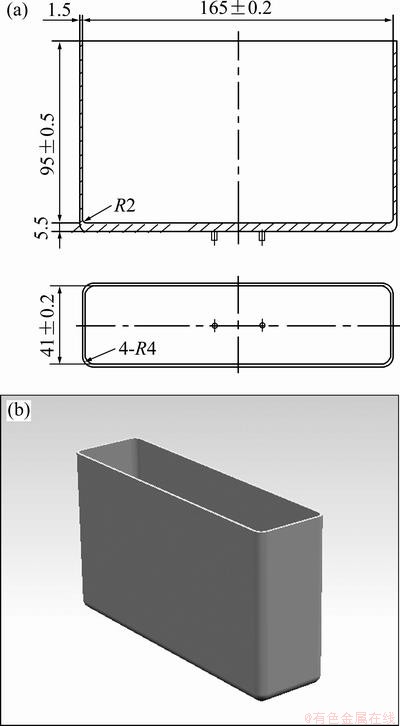
Fig. 1 2D drawing (a) and 3D drawing (b) of ECU housing (Unit: mm)
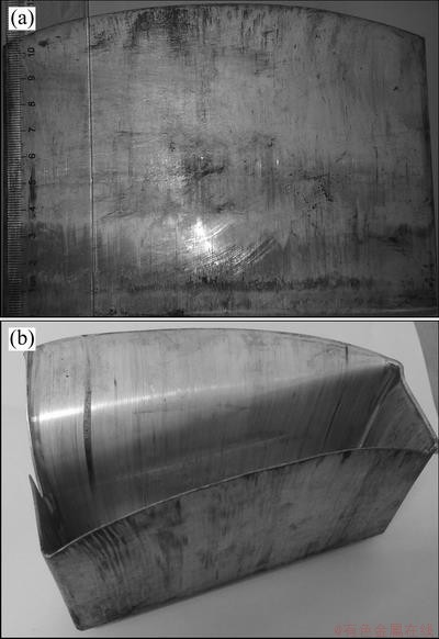
Fig. 2 Controller housing with earing (a) and cracks defects (b)
The final extruded part by simulation is shown in Fig. 3(a). It can be seen that the simulation result has a good agreement with the initial process by viewing the overall dimension. The height difference ��h of the earing defects in simulation is 14.09 mm, while the experimental value is 14.46 mm. So the absolute error is only 2.6%. The load-stroke curve of the extrusion process is shown in Fig. 3(b). In the short beginning, the extrusion load increases rapidly. But then the load becomes stable continuously. This is quite consistent with the general deformation rule of backward extrusion.
Figure 4 shows the velocity distribution. In the first stage, the outer wall and small convex columns generate at the same time. And the metal flow velocity is very fast and reaches 300 mm/s, as seen in Fig. 4(a). In the second stage, two columns have been formed completely and the velocity becomes 0. The velocity in the middle of wide edge is larger than that of the two sides, and the earing defects appear, as shown in Fig. 4(b). In the third stage, the deformation becomes steady, the metal flow velocity is consistent at the whole edge of extrusion part and its value is around 200 mm/s, as shown in Fig. 4(c). Moreover, the final shape of earing is shown in Fig. 4(d).
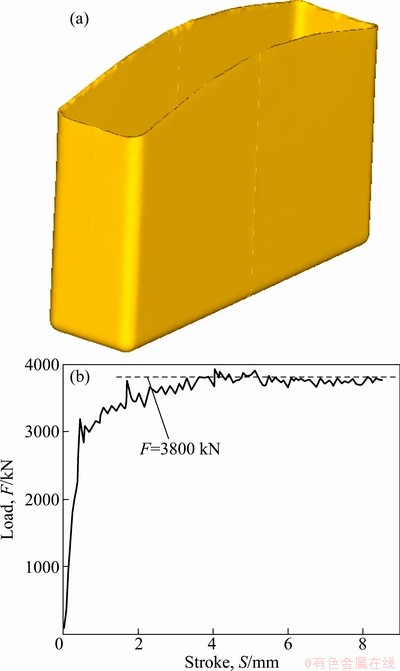
Fig. 3 Forming shape (a) and load-stroke curve (b) of initial process
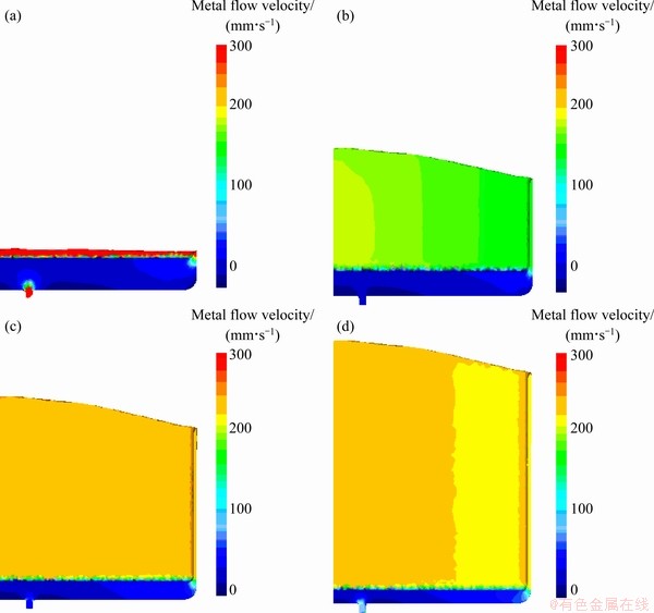
Fig. 4 Velocity distribution of the 6th step (a), 50th step (b), 80th step (c) and last step (d) in extrusion process
It is worth noting that the uneven edge of controller housing is largely attributed to the larger aspect ratio, the smaller deformation resistance along the wide edge and the non-uniform material flow along the wide edge, especially the faster material flow in the middle.
3 Process optimization
According to consistency of the initial process and its simulation and for the sake of saving time and cost, the process optimization will be implemented by utilizing FE simulation.
3.1 Modified punch
In order to improve the defects, a modified punch with resistance ribs was put forward. As shown in Fig. 5, there are a group of resistance ribs at the bottom of the punch. And the rib close to the wide edge is the longest one. To describe the characteristic of this group of resistance ribs, four key parameters are needed. They are width of the rib d, thickness of the rib t, length of the longest rib L and the inclination angle ��.
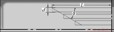
Fig. 5 Modified punch with resistance ribs
3.2 Orthogonal optimization
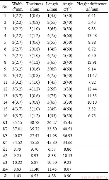
The optimization objective is to obtain a good quality of the ECU housing with the whole edge as even as possible. The orthogonal experiment is a statistical method to arrange and analyze multi-variable problem by using ��orthogonal table��. As it was mentioned above, four design variables are selected, including width of the rib d, thickness of the rib t, length of the longest rib L and the inclination angle �� for the new extrusion process with modified punch. Each variable has 4 levels, as presented in Table 1. Accordingly, an L16 (45) orthogonal table is determined, as shown in Table 2.
Sixteen simulations are carried out according to Table 2. The height difference ��h of the ECU housing along the top edge after extrusion is used to describe the earing at the edge. Specifically, the height difference ��h equals the difference between maximum and minimum height along the top edge. Of course, the smaller the height difference is, the better the design scheme will be.
Table 1 Variables and level
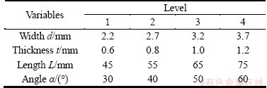
Table 2 Orthogonal table and analysis
3.3 Results and discussion
The range R listed in Table 2 indicates the sensitivity of four design variables to the height difference ��h of final extrusion part. Range is defined as the distance between extreme values of k1, k2, k3 and k4. The greater the range is, the more sensitive the variable is. Therefore, the order of influence degree of these variables can be obtained: the length of the longest rib L > the rib thickness t > the rib width d > the inclination angle ��. And the length L and thickness t are more significant than the other two. Furthermore, to illustrate the effects of four design variables on height difference ��h, it is necessary to offer the height difference-variable chart, which is shown in Fig. 6. It is clear to find that the height difference ��h increases at first and then decreases with the width d and angle ��, and the minimum values are found at the 4th level; Inversely, the height difference decreases at first and then increases with the thickness t, and the minimum value lies in the 3rd level; While the height difference increases monotonously with the length L, and the minimum value is at the 1st level.
Based on the above analysis, the optimized design variables are the width of the rib at the level 4, the thickness of the rib at the level 3, the length of the longest rib at the level 1 and the inclination angle at the level 4, namely, d=3.7 mm, t=1.0 mm, L=45 mm, ��=60��. Coincidentally, the optimized scheme is the fifteenth scheme in Table 2, and the corresponding height difference ��h is 3.32 mm. As expected, the optimal height difference ��h is the smallest one of all the sixteen design schemes.
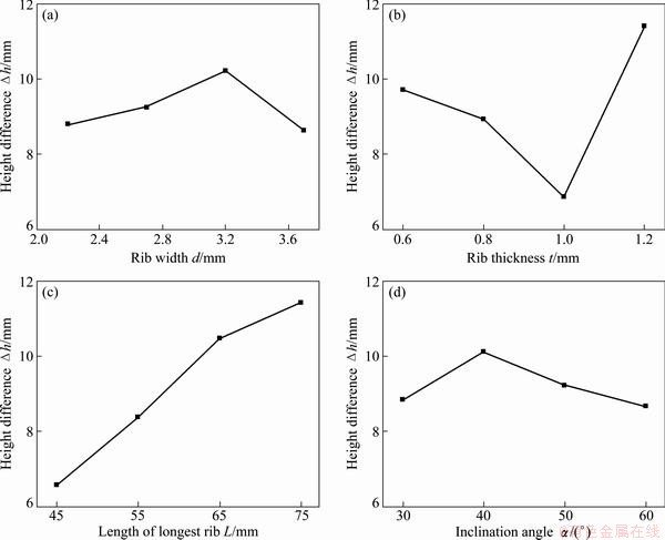
Fig. 6 Change curve for effect of each variable on the optimization objective
In the fifteenth scheme, the top edge of the controller housing is nearly even and no earing compared with initial process, as shown in Fig. 7(a). And the extrusion load rises from 3800 kN to 4050 kN according to Fig. 3(b) and Fig. 7(b), only a increase of 6.6%. Moreover, the optimized scheme still could be performed on the 6300 kN hydraulic press. This result shows that the parameter matching in the 15th scheme provides optimized metal flow which brings about good quality for cold-extruded controller housing.
4 Conclusions
1) FE simulation is adopted to analyze the earing defects appearing at the wide edge of the controller housing in initial process owing to its convenience, high efficiency and low cost. As a result, the height difference ��h of the earing in simulation is 14.09 mm and the experimental value is 14.46 mm, and the absolute error is only 2.6%. Evidently, the simulation result has a good agreement with the experimental work.
2) An extrusion process by using a punch with resistance ribs is put forward to improve the earing defects. Simultaneously, orthogonal experiment is exploited to find the optimized dimension of resistance ribs. To be specific, the height difference ��h along the top edge of the controller housing is defined as the optimized objective, and four key parameters (the width of rib d, the thickness of rib t, the length of the longest rib L and the inclination angle ��) are chosen as design variables in orthogonal experiment.
3) The optimized parameters are: d=3.7 mm, t=1.0 mm, L=45 mm, ��=60��. In this case, the height difference ��h is 3.32 mm, which decreases by 10.77 mm compared with the initial process. The earing defects are obviously improved, while the extrusion load merely increases by 6.6%. Altogether, all the results will provide the consequent improvement of process design with good guidance.
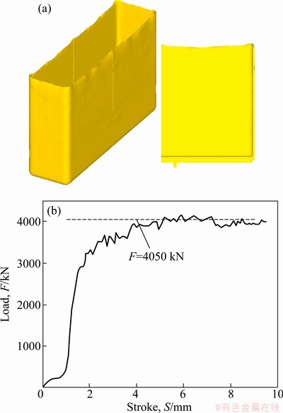
Fig. 7 Forming shape (a) and load-stroke curve (b) of optimal scheme
References
[1] KIM S H, KIM S H, HUH H. Tool design in a multi-stage drawing and ironing process of a rectangular cup with a large aspect ratio using finite element analysis [J]. International Journal of Machine Tools & Manufacture, 2002, 42(7): 863-875.
[2] PARK C S, KU T W, KANG B S, HWANG S M. Process design and blank modification in the multistage rectangular deep drawing of an extreme aspect ratio [J]. Journal of Materials Processing Technology, 2004, 153-154: 778-784
[3] XU Zi-ming. A progressive drawing die for thermal protector shell [J]. Die & Mould Industry, 2010, 36(9): 34-36. (in Chinese)
[4] LI Dao-ming, GHOSH A K. Biaxial warm forming behavior of aluminum sheet alloys [J]. Journal of Materials Processing Technology, 2004, 145(3): 281-293.
[5] ZENG Yue, DENG Zi-yu. Finite element simulation of rectangle box deep drawing [J]. Forging & Stamping Technology. 2006, 31(1): 3-5. (in Chinese)
[6] LI Jin-yan, FU Jian, PENG Bi-you, DONG Min, LIN Nan. Numerical simulation of deep drawing process about cracks at the corner of square box [J]. Journal of Plasticity Engineering, 2006, 13(6): 34-38, 47. (in Chinese)
[7] KIM H S, KOC M, NI J. Development of an analytical model for warm deep drawing of aluminum alloys [J]. Journal of Materials Processing Technology, 2008, 197(1-3): 393-407.
[8] LIN H S, TUNG C W. An investigation of cold extruding hollow flanged parts from sheet metals [J]. International Journal of Machine Tools and Manufacture, 2007, 47(14): 2133-2139.
[9] MOSHKSAR M M, EBRAHIMI R. An analytical approach for backward-extrusion forging of regular polygonal hollow components [J]. International Journal of Mechanical Sciences, 1998, 40(12): 1247-1263.
[10] YAN Hong, LIN Zhi-ping, WU Lu-shen, LOU Zhong-min. The upper-bound analysis of deformation in cold extrusion of box-shaped products [J]. Journal of plasticity engineering, 2000, 7(1): 26-30. (in Chinese)
[11] YAN Hong, LOU Zhong-ming. The upper-bound analysis of cold extrusion process for box-shaped products [J]. Materials Science and Engineering B, 2006, 132(1-2): 187-192.
[12] HEZAM L M A, HASSAN M A, HASSAB-ALLAH I M, El-SEBAIE M G. Development of a new process for producing deep square cups through conical dies [J]. International Journal of Machine Tools and Manufacture, 2009, 49(10): 773-780.
[13] KIM S H, CHUNG S W, PADMANABAN S. Investigation of lubrication effect on the backward extrusion of thin-walled rectangular aluminum case with large aspect ratio[J]. Journal of Materials Processing Technology, 2006, 180(1-3): 185-192.
[14] ZHOU Ming-zhi, XUE Ke-min. 3D elasto-plastic FEM simulation of precise extrusion process of the box-shaped work piece [J]. Journal of Hefei University of Technology. 2005, 28(8): 881-884. (in Chinese)
[15] WANG Qiang, ZHANG Zhi-min, FANG Min. Metal non-uniform flow controlling in complex box extrusing process [J]. Journal of Plasticity Engineering, 2005, 12(2): 35-37. (in Chinese)
[16] HU Zhong, ZHU Li-hua, WANG Ben-yi, LIU Zhuang, MIAO Yong-chun, XIE Pei-liang, GU Sheng-xing, SHENG Wei. Computer simulation of the deep extrusion of a thin-walled cup using the thermo-mechanically coupled elasto-plastic FEM [J]. Journal of Materials Processing Technology, 2000, 102(1-3): 128-137.
[17] SOFUOGLU H, GEDIKLI H. Physical and numerical analysis of three dimensional extrusion process [J]. Computational Materials Science, 2004, 31(1-2): 113-124.
[18] LONG H. Quantitative evaluation of dimensional errors of formed components in cold backward cup extrusion [J]. Journal of Materials Processing Technology, 2006, 177(1-3): 591-595.
���ʿ�������Ǽ�ѹ�����Ż�
������1��������1���� ��1���� ��2���� ��2
1. �Ϻ���ͨ��ѧ ���Գ��μ�����װ���о�Ժ���Ϻ� 200030��
2. ����ɭ����������˾����� 224100
ժ Ҫ��������Ͻ��������Ǽ�ѹ���ι����г��߶˲�������������ȱ�ݣ����Ȳ���DEFORM-3Dģ���������ǵļ�ѹ���ι��̡�������״��ߴ�������ģ������ʵ�ʵ����Ʋ�Ʒ��������һ���ԣ�ͨ��ģ�ⷢ�֣��������ٲ��������γɵ���Ҫԭ���ڴ˻����ϣ����һ�ָĽ����շ�����ͨ����ģ�ײ�����һ�������Ը��ƽ���������״�����������������Ʒ���������������d���������t���������L�Լ�����������γɵ���Ǧ���Ϊ��Ʊ��������Լ�ѹ���������Ƕ˲��߶Ȳ��h��СΪ�Ż�Ŀ�꣬�ԸĽ����������Ż��������Ʒ�����ȣ��Ż�������˲��߶Ȳ���ԭ����14.09 mm���͵� 3.32 mm����ȱ�����Եõ����ơ�
�ؼ��ʣ���������ǣ���ѹ����ȱ�ݣ�����Ԫģ�⣻�Ż�
(Edited by HE Yun-bin)
Foundation item: Project (51005149) supported by the National Natural Science Foundation of China
Corresponding author: ZHAO Zhen; Tel: +86-21-52580156; E-mail: zzhao@sjtu.edu.cn; clhu@sjtu.edu.cn
Abstract: Aiming to analyze the serious earing defects in initial extrusion process of aluminum controller housing, simulation was carried out by DEFORM-3D and the results showed a good agreement with the experimental work. Based on the simulation results, it is easy to find that the non-uniform velocity of metal flow is the main cause leading to earing defects. Therefore, a novel process scheme which tried to avoid the defects by using a punch with a group of resistance ribs at the bottom was put forward. For further study, the orthogonal experiment method was adopted to optimize the novel process. The width of the rib d, the thickness of the rib t, the length of the longest rib L and the inclination angle �� were selected as design variables, and the height difference ��h along the top edge of the controller housing after extrusion which could reflect the earing was determined as the optimized objective. Finally, the optimized scheme was obtained. Compared with the initial process, the height difference ��h was reduced to 3.32 mm from 14.09 mm and the earing defects have been obviously improved in the optimized scheme.
