

J. Cent. South Univ. (2020) 27: 2227-2238
DOI: https://doi.org/10.1007/s11771-020-4444-5

Manufacturing of ultra-large plate forgings by unfolding and flattening of thick cylinders
DENG Zheng-hua(������)1, 2, WEN Tong(��ͮ)1, YOU Jian-hao(�ν���)1,DU Kang-kang(�ſ���)1, SUN Lei(����)2
1. College of Materials Science and Engineering, Chongqing University, Chongqing 400044, China;
2. Erzhong (Deyang) Heavy Equipment Co. Ltd., Deyang 618000, China
 Central South University Press and Springer-Verlag GmbH Germany, part of Springer Nature 2020
Abstract:
Ultra-large plate forgings are foundation of heavy machinery, but many parts of the type cannot be made by conventional technologies due to the characters of extreme manufacturing in terms of size and quality requirements. This paper introduced a systematically method called cylinder unfolding method (CUM) for producing large plate forgings, by using a serial of operations including ��splitting��, ��unfolding��, and ��flattening�� of a thick cylinder obtained from saddle forging. The technological route of CUM was presented in detail with an example of plate forging with the horizontal sizes of 6100 mm and thickness of 300 mm. The deformation features of saddle forging for fabricating transitional cylinders were analyzed, and then the subsequent handling steps including splitting, unfolding and flattening of the cylinder, as well as the auxiliary processing, were addressed. The practice proved that CUM can provide an efficient way for manufacturing ultra-large plate forgings and meet the strict requirements in geometry and mechanical performance, without highly increasing the investments of forming equipment and tooling.
Key words:
extreme manufacturing; ultra-large plate forging; cylinder unfolding method; metal forming��
Cite this article as:
DENG Zheng-hua, WEN Tong, YOU Jian-hao, DU Kang-kang, SUN Lei. Manufacturing of ultra-large plate forgings by unfolding and flattening of thick cylinders [J]. Journal of Central South University, 2020, 27(8): 2227-2238.
DOI:https://dx.doi.org/https://doi.org/10.1007/s11771-020-4444-51 Introduction
Plates are fundamental structural components with the geometric feature where the thickness is far less than length and width. Large, thick plates are widely used in heavy industrial fields such as metallurgy, machinery, electric power, petroleum, chemical, shipbuilding, aviation [1, 2]. There is no specific definition of the range of ��large��: it depends on the relative size compared to the common production capacity of the equipment in industrial fields. Generally, if the plane dimensions of a plate exceed 5000 mm and the thickness is larger than 200 mm, it can be considered to be a large one.
Besides the geometric requirements in shape and dimension, the organization structure and mechanical properties of large forgings must be taken into full consideration to meet the rigorous demands in service. So far, manufacturing technologies of plates mainly include rolling and free forging [3]. Rolling is suitable for mass production, and the surface quality is good. However, the equipment investments are huge, and the maximum sizes of the rolled plates are limited and the anisotropy is obvious. Since plates with jumbo sizes are usually small-lot or even single-piece customized production with diverse materials and shapes, in most cases, free forging on press is the only choice for producing these part types.
Typically, a free forging process is started from a cast ingot and the formation of final workpiece is accumulated by progressive deformations of billet under repeatedly compressing in several separated stages. To obtain sound organization with fine grains and defect-free structures, as well as appropriate distribution of second phase and non-metallic inclusions, suitable stress states must be achieved during forming, and large plastic deformations under the action of multiple compressive stress components are necessary [4, 5]. To this end, a couple of technologies for free forging of oversize workpiece have been developed, for example, the methods of FM (free from mannesmann effect), WHF (wide-die heavy-blow forging) and JIS (Japan�CTefeno-Shikano), etc [6-8].
With the ever increasing trend towards large capacity, high power and high performance in many industrial fields, the component size continues to grow. There are huge difficulties in technical and economic aspects for the manufacturers to perform the production of large parts. For example, when the dimension of forging reaches certain level, it is hard to find appropriate equipment to undertake the task. For large plates with high ratio of width/length to thickness, the compressive stress state inside the workpiece cannot be totally satisfied by normal operation, and then destructive internal defects are prone to be incurred [9]. Under each compaction of press, the material flows along different directions are not equal. Therefore, it is hard to precisely control specific dimension. Furthermore, for the formation of rectangular plates, it is difficult to fulfill the corners from a columnar billet with a round shape. The ingot size must be increased to obtain sufficient areas, inevitably leading to low rate of material usage.
After many years of exploration and practice, Erzhong (Deyang) Heavy Equipment Co. Ltd. (EHEC) of China has established a serial of forming technologies of super-large plate forgings based on a unique process by unfolding and expanding of thick cylinders, herein called CUM (cylinder unfolding method) [10, 11]. The method has been successfully applied in the productions of large plate forgings in the domains like forming press, nuclear power plant, petrochemical industry, etc. In the current paper, technological procedure of CUM is discussed in detail by taking an example of plate forging at the dimension level of 6000 mm. The deformation characteristics, typical and key operation steps of the method were addressed.
2 Methodology for producing ultra-large plate forgings by CUM
Figure 1 illustrates the technological procedure of CUM. It starts from a casting ingot and consists of a series of operations where different processing steps, preprocessing, upsetting, piercing, elongating, saddle forging, splitting and flattening, are involved to produce the large plate. Depending on the plate size and forming plan, a cylinder can comprise of one piece of plate or more plates.
In the early stages, a columned billet is fabricated by chamfering and elongating of the steel ingot. The ingot heads, including the nozzle and the riser area where casting defects commonly exist, are cut away. During upsetting, it is crucial to guarantee the symmetry of workpiece and avoid askew shape. Piercing is the next step of upsetting, in which the defective organizations within the core can be removed.
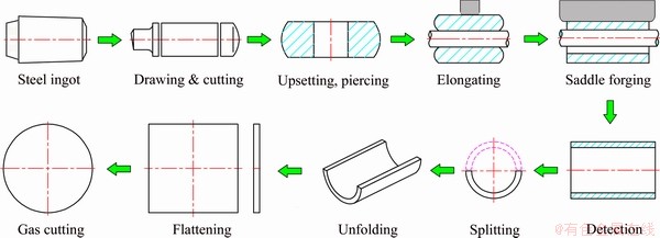
Figure 1 Technological procedure for fabricating large plate forgings by CUM
In the step of elongating, the length of bored forging is enlarged under the compaction of the upper and lower anvils on press, while the outer diameter decreases. The upper anvil is a flat, axially oriented short block, and the lower anvil is a round mandrel bar that rests on the supports at each end of the forging. During operation, the hollow forging is driven to rotate by the mandrel bar.
In the step of saddle forging, wall thickness of the hollow forging reduces and the diameter increases, while the axial length remains constant. The tooling in saddle forging is similar to those in elongating step, and the cylinder can also be driven to rotate by the mandrel bar. However, the upper anvil is a long block covers the entire axial length of cylinder. Saddle forging is the key step in the whole formation process, since it largely determines the final quality of plate. To guarantee the shape and eliminate the probability of residual defects within riser area, the required thickness and diameter must be achieved and then remove excess material at both ends of the cylinder by gas cutting. After obtaining the cylinder, the plate forging is formed by splitting, unfolding and flattening of thick shell. To meet high quality requirement, it is crucial to strictly control the uniformity of material flow and prevent abnormal deformation or local damage. Generally, damage inspections are conducted in all the steps.
Compared with the conventional free forging of large plates, the required load in CUM is less due to the manner of incremental forming. Sufficient plastic deformation and mechanical properties can be obtained under such conditions. Another pronounced benefit in the forming of rectangular plates by CUM is that the corners can be easily fulfilled.
When making the forming plan, the geometry and technical requirements should be considered on the basis of the capability of available equipment. Generally, the relationships between the workpiece and main parameters of press/tooling include:
1) Clear height of press determines the maximum diameter of forged cylinder;
2) Column distance of press determines the maximum diameter of cylinder, and the maximum dimension of flattened plate forgings;
3) Crane capacity determines the maximum weight of forgings;
4) Heating furnace size determines the maximum size of ingots and billets;
5) Heat treatment furnace size determines the maximum size and weight of finished products;
6) Anvil length determines the maximum length of cylinder;
7) Revolving platform determines the maximum length of flattened plate forgings.
3 Sample product for CUM analyses
As shown in Figure 2, the target part is a semi-spherical shell with the inner radius of 2350 mm and wall thickness of 210 mm. It is a typical seal head in nuclear power plant. The final shape is formed by drawing a plate forging. The material is SA508Gr3 (ASME SA508 class 3) steel, which is extensively used in the shells of nuclear reactor pressure vessels (RPV) and steam generators (SG) due to the properties like good toughness and high weldability [12]. The flaw detection is conducted according to the ASME standard of forging production of nuclear power.
To fabricate the huge plate by CUM, a transitional cylinder with weight of about 200 t, comprising of two pieces of plate, is designed, as shown in Figure 2. The original size of the billet in saddle forging is ��2800 mm��1500 mm��6350 mm, and the mandrel size is 9000 mm����1500 mm. The forming equipment is a hydraulic press with e capacity of 160 MN.
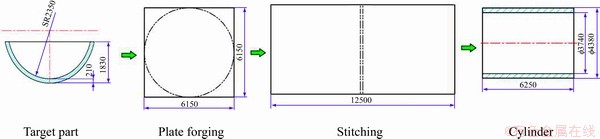
Figure 2 Designing of plate forging and transitional cylinder according to target part of seal head (Unit: mm)
Since the plastic deformation is large and dominating, rigid-plastic FEM was used to analyze the processes. The numerical simulations were carried out in Deform-3D . The calculations of the serial steps were continuously conducted according to the procedure of CUM, using the MO (multiple operation) module with the strains in previous steps inherited. Main parameters in the calculations are listed in Table 1. The initial temperatures of ingots, anvil and mandrel are 1250 ��C and 300 ��C, respectively. The high-temperature rheological parameters of SA508Gr3 steel (as shown in Figure 3) employed in the simulation were generated by the isothermal compressive test, which is widely used to obtain stress�Cstrain data of metals in plastic deformation at elevated temperature [13].
Table 1 Parameters in FEM simulation
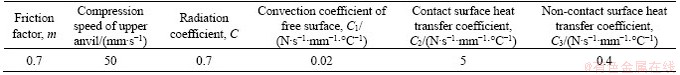
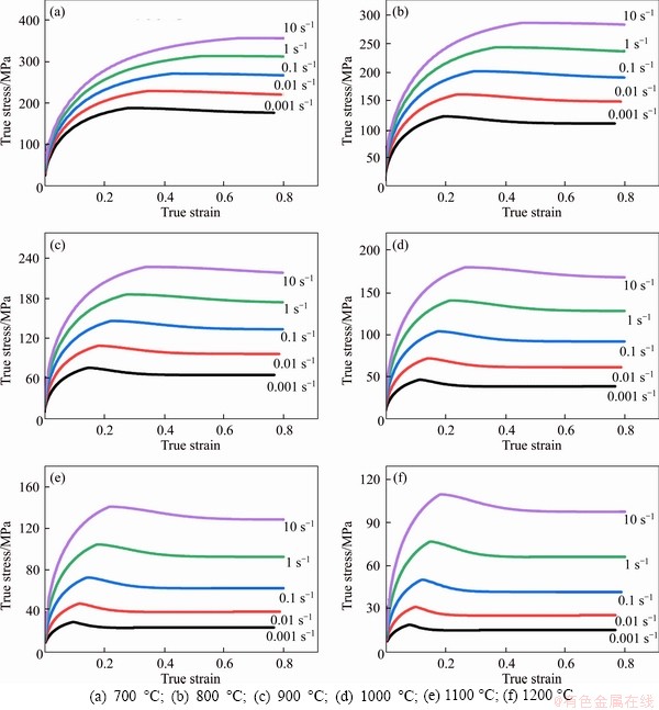
Figure 3 Flow curves of SA508Gr3 at different temperatures:
4 Results and discussion
4.1 Deformation analysis of saddle forging
During saddle forging, formation of the thick cylinder is accomplished by cumulative plastic deformation under repetitively localized loading. In each stroke of press, the deformation zone of billet between the anvil and mandrel is a strip shape, as the shadow area shown in Figure 4. The triaxial compressive stress state is benefit to eliminate the flaws like pores that may exist. Due to the large ratio of relative length to width/thickness, in theory it is a plane deformation mode and the change of strip length is negligible during forming [11]. Under such condition, the cylinder extends circumferentially with diameter enlarging and thickness decreasing, while the axial length keeps almost unchanging.
To guarantee sufficient and uniform deformation during forming, compression amount ��S of the upper anvil in each stroke should be appropriately controlled. As shown in Figure 4, the relationship between ��S and geometries of the cylinder and mandrel can be written as:

 (1)
(1)
where �� is the center angle corresponding to the deformation zone; L is the width of deformation zone; D is the outer diameter of the cylinder.
Figure 5 shows the simulation results with various ��S values. It can be seen that the shape of deformation zone changes with ��S. The maximum strain gradually moves towards the mandrel with the increase of ��S. Small ��S means small load, and the deformation of inner wall is also small. Under such circumstance, it is easier to rotate the mandrel in the subsequent operations and the wall surface quality is better. However, small deformation is not benefit to cure the internal defects inside the workpiece and the production efficiency is low. On the contrary, large ��S would cause more deviation of the gravity center of the forging, making it difficult to rotate the cylinder on the mandrel. In practice, since it is difficult to accurately control ��S, in the first run of the operation ��S is selected to be large, and then decreases it to obtain smooth surfaces of internal and external walls. As for the sample in the current study, the original thickness of the hollow ingot is about 640 mm and the final thickness of the cylinder is about 305 mm, and the reasonable ��S can be controlled within the range of 50-150 mm.
As aforementioned, under the plane strain deformation mode, material flow along axial direction in each compression of press during saddle forging is small. Nevertheless, in the early stage, since the relative thickness t/d (t is the cylinder thickness; d is the outer diameter of cylinder) of the cylinder is large, the deviation from plane deformation condition is obvious and therefore, there is slight axial elongation of the cylinder.
Figure 6 shows the variation of axial deformation and force feature of the cylinder under different ��S values. The stress triaxialities were measured at the center point of the deformation zone of cylinder. It can be clearly seen that the axial elongation and the forming load increase with the compression amount. Following each compression of the upper anvil, the cylinder position is adjusted through rotating the mandrel. The hollow forging is rotated with the mandrel by friction force at the interface. The rotation angles of the cylinder must be properly controlled. For instance, if the angle is large, ��ripples�� on the surface after forming will be pronounced and the wall thickness difference is large, making it difficult to handle in the subsequent steps. Conversely, if the rotation angle is small, the productivity is reduced and the operating time will be too long, increasing the risk of forming due to more temperature reduction. In the current study, when ��S of anvil is 150 mm, the width of deformation zone L is 1060 mm, as shown in Figures 4-7. Moreover, if the gap between the cylinder and the mandrel bar is small, the corresponding center angle �� can be roughly determined by the center angle, the mandrel diameter and the inner diameter of the cylinder. However, with the progress of body expanding, it is difficult to accurately estimate the contact positions of the mandrel and cylinder. According to the part dimension in the current study, rotation angle of the mandrel and cylinder during each compression of upper anvil can be set to about 30��-35��.
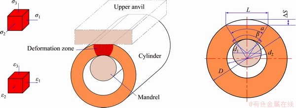
Figure 4 Deformation zone and geometrical relationship of cylinder in saddle forging
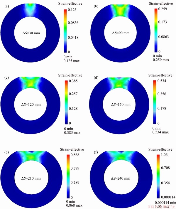
Figure 5 Cylinder deformation and strain distributions under various ��S values of upper anvil
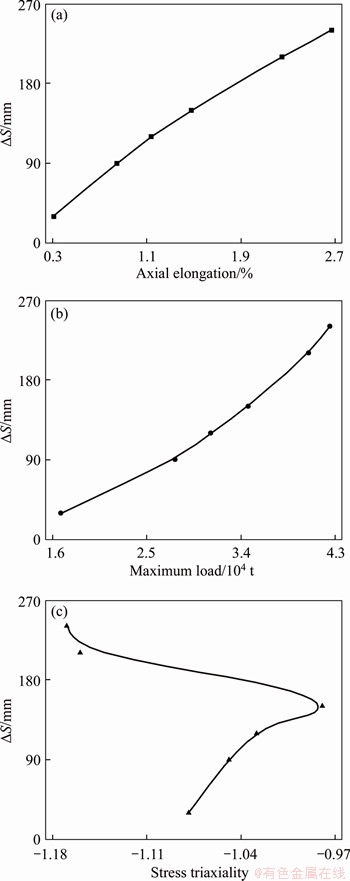
Figure 6 Deformation and force features of cylinder under different ��S values in saddle forging
At the late stages of saddle forming, the wall becomes thinner and it is more close to plane strain deformation mode in each stroke of the upper anvil. To precisely control the wall thickness, the anvil movement is measured in time according to the ruler lines on press frame. Meanwhile, to prevent the shape defects like horn, parallelogram and horseshoe, the forging positions are located using laser measurement systems. Figure 8 shows the final state of the transitional cylinder forging. It can be seen that the outer surface is smooth.
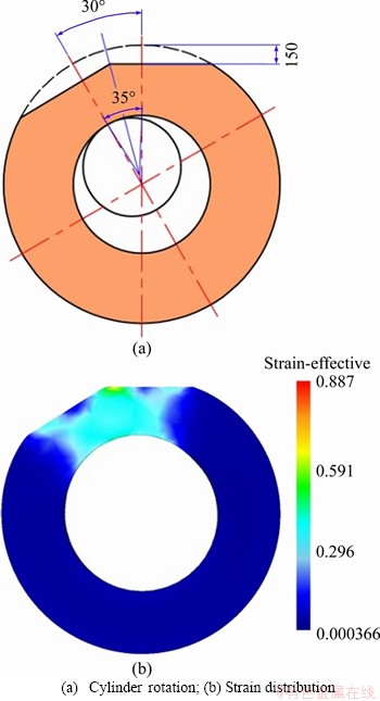
Figure 7 Geometrical relationship of:
4.2 Splitting of cylinder
In order to perform the subsequent processes, the transitional thick cylinder must be separated into halves by gas cutting. Before operation, mark lines are accurately drawn on the body. In view of possible conditions of uneven and irregular shape of the cylinder, e.g., ellipticity and taper-shape to certain degree, laser measuring devices can be used to assist. As shown in Figure 8, the cylinder is horizontally placed on a working table and then the lines are drawn on the surface with markers.
After drawing mark lines, gas cutting tools located on the special sliding rails are employed to perform the cutting along the cylinder axis, symmetrically separating the cylinder into two semicircular shells (see Figure 9). To avoid cracking of the material, the cylinder body was preheated with the temperature higher than 300 ��C. Meanwhile, temperature measurement is periodically conducted in accordance with the time schedule.

Figure 8 Cylinder forging and laser assisted drawing of mark lines
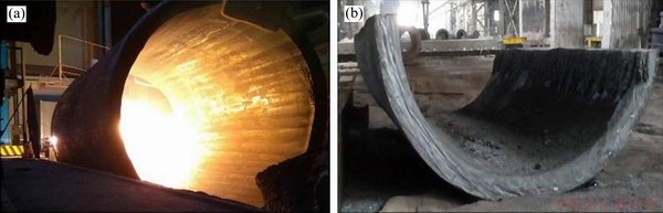
Figure 9 Gas cutting of thick cylinder (a) and obtained semicircular shell forging (b)
After obtaining the curved shell forgings, heat treatment and surface cleaning are carried out. By the method, tidy cut edges can be obtained and the smoothness of internal and external surface of the shell forging can be guaranteed. The reserved machining allowance considers the occurrence of defects, such as collision and impact pit during subsequent processes.
4.3 Unfolding and flattening of semicircular shell
After being cut into halves, the semicircular thick shell will be unfolded and flattened. During operation, the forging needs to rotate on the platform to ensure that all areas can be compressed by hammer. The dimensions of platform and the distances between the press columns should be larger than the corresponding dimensions of the workpiece. In fact, to guarantee that there is no conflict between the workpiece and equipment, a comprehensive analysis of the operating details during the entire process is necessary.
As shown in Figure 10, there are three schemes for unfolding the semicircular shell. Comparatively speaking, Plan A requires a high supporting block and thus the risk during handling may increase. Meanwhile, the opening width of the shell is limited by the width of supporting block. In addition, it is difficult to load/unload and turn the workpiece after unfolding. In Plan B with round tooling, the indentation on the inner shell surface after forming is small. However, there are uncertain factors of potential safety hazards such as rolling, moving and others during operation. In Plan C, it is easy to load/unload the forging and the flattening operation can be directly carried out after unfolding, without turn over the workpiece. To avoid the possible interference, the upper anvil (comprises an anvil seat and a hammer head) can be placed on the plate, and then the fixed hammer of the press moves downwards, compressing the hammer head several times and stretch the shell as wider as possible. The edges of the hammer head were rounded to reduce damage on the surface. By Plan C, the semi-cylinder shell forging can be successfully unfolded and extended to the required size, as shown in Figure 11.
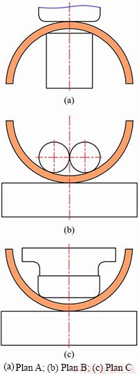
Figure 10 Plans for unfolding semicircular thick shell:
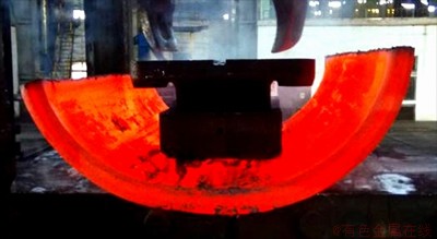
Figure 11 Unfolding of semicircular thick shell forging
Flattening is the follow-up step after unfolding, where the horizontal sizes of the workpiece enlarge. Although integral compression on the forging that covers the whole plate may attain higher flatness and more regular shape, the tonnage and platform space of the press are seriously insufficient. Since the length and width of the anvil are limited, the workpiece must be constantly moved to ensure that all areas can be formed. Under such circumstance, localized wavy indentations on the surface are inevitably incurred, bringing huge risk to the process, especially when the machining allowance is small. For this reason, a step by step forming scheme using a compressing pad with diameter of 4000 mm is adopted, as shown in Figures 12 and 13.
The two lateral cut edges of the shell and adjacent areas are hard-to-deformation zones.
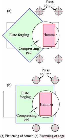
Figure 12 Schematic diagram of flattening of corner and edge of plate forging with compressing pad:
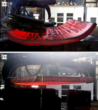
Figure 13 Flattening of thick shell with compressing pad (a) and lifting with tong (b)
During flattening, the compressing pad is placed upon the edge as shown in Figure 13, making sure that the pad center is located inside the workpiece with a distance of 1000 mm or more from the edge. To prevent damage on the surface, small and progressive compactions of the tooling are employed, with continuous moving of the pad positions. Furthermore, a wide angle tong with the open diameter larger than 6000 mm was used to clamp and rotate the forging during operation.
For the plates with final shape of circular outline, the four sharp corners of the semi-cylinder can be removed in advance to make it easier to flatten.
4.4 Steps of auxiliary processing and quality control
After flattening, heat treatments are carried out to perform dehydrogenation, stress elimination and organization adjustment, laying a proper foundation for the subsequent processing of the plate forging. Figure 14 shows the finished thick plate and the final state of water tank head.
For large forgings, qualities in terms of geometry and structure properties such as grain size, mechanical performance, are the primary focuses in the whole forming procedure. With the technological developments in recent years, many modern technologies including the numerical control precision cutting, non-contact real-time omnidirectional 3D detection, non-destructive examinations and others, can be utilized to assist the quality control [14-18].
CUM has a built-in advantage for the manufacturing of large plate forgings. Most of the segregation belt within the casting ingot center can be removed during piercing step, and the combined operations of upsetting, lengthening and saddle forging can effectively eliminate the anisotropy of the plate and exploit the advantages of plastic forming to the full. Figure 15 shows the microstructure of the material within the plate corners. It can be seen that the microstructures are uniform. In fact, through the combination of plastic deformation and heat treatment, the qualified rates of the obtained plate forgings in terms of geometry and ultrasonic inspection can reach almost 100%.
5 Conclusions
With the upsizing trend of heavy machinery, more and more productions of components exceed the capability of existing technologies. Due to the complicated and long processing chains and high commercial value, it is of great risk to handle the manufacturing of large forgings with strict quality requirements. This paper presented a systematical method called cylinder unfolding method (CUM) for producing ultra-large plate forgings. With the unique loading and deformation manners, CUM can meet the quality requirements of large plate forgings. The technology has been maturely used in EHEC for many years and has been proved to be reliable and affordable. From 2014 to 2018, nearly 100 large plate forgings of nuclear power plants, petrochemical hydrogenation reactors and others have been successfully fabricated by CUM, without extra investments of expensive equipment and tooling.
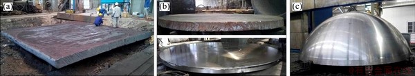
Figure 14 Different states of workpiece
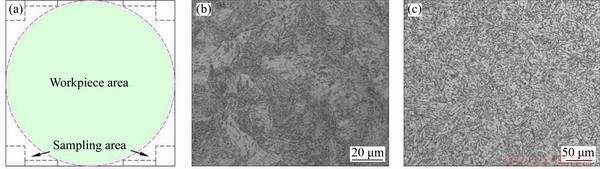
Figure 15 Sampling area of plate forging (a) and microstructure in scales of 500 X (b) and 200 X (c)
References
[1] TSUKADA H, SUZUKI K, SATO I. Ultra-large size austenitic stainless steel forgings for a fast breeder reactor: development, manufacturing and properties achieved [J]. Nuclear Engineering and Design, 1987, 102(3): 495-503. DOI: 10.1016/0029-5493(87)90194-4.
[2] BERGER T, MURAI E, KURIHARA I. Manufacturing and properties of nozzle shell with integral flange for EPR reactor pressure vessel [J]. Iron Making and Steel Making, 2007, 34: 205-210. DOI: 10.1179/174328107X174717.
[3] LIU Guo-hui. Forging technology of heavy plate- shaped forgings [J]. Forging & Stamping Technology, 2005, 2: 4-6. (in Chinese)
[4] JHA A, SREEKUMAR K, THARIAN T. Process optimization for high fracture toughness of maraging steel rings formed by mandrel forging [J]. Journal of Manufacturing Processes, 2010, 12(1): 38-44. DOI: 10.1016/ j.jmapro.2010.01.007.
[5] KAKIMOTO H, ARIKAWA T, TAKAHASHI Y. Development of forging process design to close internal voids [J]. Journal of Materials Processing Technology, 2010, 210(3): 415-422. DOI: 10.1016/j.jmatprotec.2009.09.022.
[6] ONODERA S, KAWAGUCHI S, TSUKADA H. Manufacturing of ultra-large diameter 20MnMoNi 5 5 steel forgings for reactor pressure vessels and their properties [J]. Nuclear Engineering and Design, 1985, 84(2): 261-272. DOI: 10.1016/0029-5493(85)90196-7.
[7] ERVE M, PAPOUSCHEK F, FISCHER K. State of the art in the manufacture of heavy forgings for reactor components in the Federal Republic of Germany [J]. Nuclear Engineering and Design, 1988, 108(3): 485-495. DOI: 10.1016/0029-��5493(88)90238-5.
[8] FENG Chao, CUI Zhen-shan, LIU Ming-xiang. Investigation on the void closure efficiency in cogging processes of the large ingot by using a 3-D void evolution model [J]. Journal of Materials Processing Technology, 2016, 237: 371-385. DOI: 10.1016/j.jmatprotec.2016.06.030.
[9] LEE Y, LEE S, TYNE C. Internal void closure during the forging of large cast ingots using a simulation approach [J]. Journal of Materials Processing Tech, 2011, 211(6): 1136-1145. DOI: 10.1016/j.jmatprotec.2011.01.017.
[10] FENG Fa-ming. Research on the forging process for heavy wide-thick plate blanks [J]. Heavy Casting and Forging, 1996(2): 20-22. DOI: 10.14147/j.cnki.51-1396/tg.1996.02. 005. (in Chinese)
[11] WANG Xin-peng, WEN Tong, LIU Pan. Deformation analysis of large cylinder with mandrel reaming process [J]. Hot Working Technology, 2010, 39(11): 53-56. DOI: 10.14158/j.cnki.1001-3814.2010.11.011. (in Chinese)
[12] SUN Ming-yue, HAO Lu-han, LI Shi-jian. Modeling flow stress constitutive behavior of SA508-3 steel for nuclear reactor pressure vessels [J]. Journal of Nuclear Materials, 2011, 418(1-3): 269-280. DOI: 10.1016/j.jnucmat.2011.07.��011.
[13] WEN Tong, LIU Lan-tao, HUANG Qian. Evaluation on prediction abilities of constitutive models considering FEA application [J]. Journal of Central South University, 2018, 25(6): 1251-1262. DOI: 10.1007/s11771- 018-3822-8.
[14] MAYER K, BERGER C, GNIRSS G. Investigations by non-destructive inspection to determine the size of natural defects in large forgings of turbogenerators [J]. Nuclear Engineering and Design, 1993, 144(1): 155-170. DOI: 10.1016/0029-5493(93)90017-4.
[15] HASELHOFF W, MAIDORN C, HERINGDORF J. Experience with the fabrication of thick-walled forgings of X5 CrNi 13 4 for the primary circuit of pressurized water reactors [J]. Nuclear Engineering and Design, 1986, 94(3): 211-219. DOI: 10.1016/0029-5493(86)90003-8.
[16] ZHANG Yu-cun, HAN Jun-xia, FU Xian-bin. Measurement and control technology of the size for large hot forgings [J]. Measurement, 2014, 49: 52-59. DOI: 10.1016/ j.measurement.2013.11.028.
[17] ARIKAWA T, YAMABE D, KAKIMOTO H. Influence of anvil shape of surface crack generation in large hot forging process [J]. Procedia Engineering, 2014, 81: 480-485. DOI: 10.1016/j.proeng.2014.10.026.
[18] TANAKA Y, SATO I. Development of high purity large forgings for nuclear power plants [J]. Journal of Nuclear Materials, 2011, 417(1-3): 854-859. DOI: 10.1016/ j.jnucmat.2010.12.305.
(Edited by ZHENG Yu-tong)
���ĵ���
�����Ͱ�ͼ���Ͳ��չ�����췽��
ժҪ��������ƽ��ͼ������ͻ�е��ҵ�Ļ��������������ڳߴ������Ҫ������м���������ص㣬�������͵���������ô�ͳ�������졣����ϵͳ������һ�ֳ�ΪͲ��չ����(CUM)�ķ���������ͨ�����������õ��Ĺ��ɺ��ԲͲ����������չ����ѹƽ��һϵ�в�����ʵ�ִ��Ͱ�ͼ���������ˮƽ�ߴ�6100 mm�����300 mm�İ�ͼ�Ϊ������ϸ������CUM�Ĺ���·�ߣ�������ԲͲ���������̵ı����ص㣬������Ͳ��������չ����չƽ�Ⱥ������������Լ�������������ʵ��֤����CUM�ṩ��һ����Ч�ij�����ƽ��ͼ������������������������豸��ģ��Ͷ�ʵ�ͬʱ�������Ƽ����κͻ�е���ܵ�Ҫ��
�ؼ��ʣ��������죻�����ͼ���Ͳ��չ��������������
Foundation item: Project(cstc2018jcyjAX0159) supported by the Natural Science Foundation of Chongqing, China; Project(51575066) supported by the National Natural Science Foundation of China
Received date: 2019-06-17; Accepted date: 2020-04-21
Corresponding author: WEN Tong, PhD, Professor; Tel: +86-23-65127306; E-mail: wentong@cqu.edu.cn; ORCID: https://orcid.org/ 0000-0003-3266-2212
Abstract: Ultra-large plate forgings are foundation of heavy machinery, but many parts of the type cannot be made by conventional technologies due to the characters of extreme manufacturing in terms of size and quality requirements. This paper introduced a systematically method called cylinder unfolding method (CUM) for producing large plate forgings, by using a serial of operations including ��splitting��, ��unfolding��, and ��flattening�� of a thick cylinder obtained from saddle forging. The technological route of CUM was presented in detail with an example of plate forging with the horizontal sizes of 6100 mm and thickness of 300 mm. The deformation features of saddle forging for fabricating transitional cylinders were analyzed, and then the subsequent handling steps including splitting, unfolding and flattening of the cylinder, as well as the auxiliary processing, were addressed. The practice proved that CUM can provide an efficient way for manufacturing ultra-large plate forgings and meet the strict requirements in geometry and mechanical performance, without highly increasing the investments of forming equipment and tooling.
