

J. Cent. South Univ. (2021) 28: 2499-2513
DOI: https://doi.org/10.1007/s11771-021-4782-y

Experimental investigation on basic law of rock directional fracturing with static expansive agent controlled by dense linear multi boreholes
ZHAO Xing-long(������)1, HUANG Bing-xiang(�Ʊ���)1, CHENG Qing-ying(����ӭ)2,WANG Chang-wei(����ί)1, CHEN Shu-liang(������)3
1. State Key Laboratory of Coal Resources and Safe Mining, China University of Mining and Technology, Xuzhou 221116, China;
2. Jiangsu Key Laboratory of Fire Safety in Urban Underground Space, China University of Mining and Technology, Xuzhou 221116, China;
3. Office of Laboratory and Equipment Management, China University of Mining and Technology,Xuzhou 221116, China
 Central South University Press and Springer-Verlag GmbH Germany, part of Springer Nature 2021
Abstract:
Directional rupture is one of the difficult problems in deep rock mechanics and engineering. A directional fracturing method with static expansive agent controlled by dense linear multi boreholes is proposed. A physical experiment is designed and performed to investigate the basic laws of this method. The fracture initiation and propagation process, and the mechanism of directional fracturing are analyzed. The results indicate that a directional fracture is formed along the direction of boreholes layout through directionally fracturing with static expansive agents controlled by the dense linear multi boreholes. According to the variation of strain and the distribution of associated acoustic emission (AE) events and energy, the experiment can be divided into three stages. In the first stage, the static expansive agent expand slowly with no fracturing inside the rock. In the second stage, some initial micro-fracturing occurs inside the rock. In the third stage, a wide range of fracturing occurs inside the sample. The internal micro-fracturing planes are connected to form a macro-fracture. Finally, it propagates to the surface of the sample. The directional fracturing plane presents a relatively smooth plane with little bias but much local fluctuation.
Key words:
Cite this article as:
ZHAO Xing-long, HUANG Bing-xiang, CHENG Qing-ying, WANG Chang-wei, CHEN Shu-liang. Experimental investigation on basic law of rock directional fracturing with static expansive agent controlled by dense linear multi boreholes [J]. Journal of Central South University, 2021, 28(8): 2499-2513.
DOI:https://dx.doi.org/https://doi.org/10.1007/s11771-021-4782-y1 Introduction
The directional rupture of rock is essential for the rock excavation engineering, such as deep underground tunnels, chambers, railway tunnels, the slope of open-pit mines, and dams [1-3]. It is a key technology that is used to guarantee the excavation quality of surrounding rock and slope. It also can be used to reduce the over-excavation and underbreak, as well as control the ground. The rock directional fracturing technology has been widely used in many engineerings, such as mining, water conservancy, hydropower engineering, traffic engineering, civil air defense works, and architecture projects. Some techniques need to be developed to change the rock stress states and generate tangential tensile stress concentration in the desired direction to make the rock fracturing directionally. The tensile stress in the desired direction will preferentially satisfy the rupture conditions, and the directional fracture plane will be generated.
Currently, the common rock directional fracturing methods are directionally controlled blasting [4-7] and directional hydraulic fracturing [8, 9]. Directional controlled blasting can achieve barely satisfactory directional fracturing effects. But it will demolish the surrounding rock of the borehole. Due to over-excavation and underbreak, the desired quality of surrounding rock cannot be guaranteed [10, 11]. Therefore, making the rock fracture directionally and the surrounding rock be protected from being damage is an urgent problem for the rock directional controlled blasting. The related research on the method of pre-water jet slotting and directional hydraulic fracturing in boreholes indicate that the wall of the borehole initially fractures along the pre-slotting, which can guide the crack initiation of the hydraulically fractured hard roof [9, 12]. Once the hydraulic cracks are formed, they will veer spatially due to the comprehensive impacts of in-situ stress and other factors. The mining process can directly alter the stress distribution around the boreholes, which will affect the directional propagation of the cracks. Therefore, the orientation effect is not good, or the effective range is very limited [13].
The static expansive agent is a non-combustible and non-explosive material. It doesn��t generate toxic or harmful gases and no harm to human health, which makes it environment-friendly [14]. The static expansive agent is mainly composed of calcium oxide (CaO). It will generate calcium hydroxide through a hydration reaction, which is the resource of expansion when mixed with water [15-17]. Water content and ambient temperature are the principal factors on the expansive pressure. Low water content causes the hydration to act inadequately, while high water content can produce side effects diluting the agents and weakening the expansive ability [18]. High ambient temperature aids in making the hydration action generate more heat, which further increases the expansive pressure. Existing studies show that the static expansive agent generates the biggest expansive pressure when the ambient temperature is 34 ��C and the water content is 30% [19, 20]. The borehole diameter also influences the expansion progress of the expansive agents [21, 22]. The stress caused by expansive cement in boreholes also has been studied through theoretical and numerical analysis [23, 24]. The surface and bottom effect of a Bristar borehole with a finite depth are investigated. The existence of the free surface makes the tangential tension stress larger than that for the infinite medium. On the contrary, in the neighbourhood of the bottom of borehole, the tangential stress for the infinite medium is larger than that for the semi-infinite medium. Also, a design formula to determine the distance between holes to fracture is given [23].
One of the applications of the static expansive agent is for rock fracturing [25-28]. Using the static expansion demolition agents to fragment rock for the safe demolition of concrete structures and excavation of rock has achieved ideal operating effects. Compared to hydraulic fracturing which can produce a single fracture in the rock, multiple radial fractures can be observed around the injection borehole where the static expansive agent is used. Since the static expansive agent can produce a superior network of fractures, it has been applied to the rock fragmentation to enhance hard roof caving in underground mines [29]. However, the lack of knowledge about the static expansive agent controlled fracturing process is one of the main causes of its poor market value [14].
The previous researches mainly focus on rock fragmentation by inducing multiple random cracks inside the rock. Since the crack generation is random and the fracturing direction cannot be controlled, this rock-breaking technology has not been applied to the field of directional fracturing in rock engineering. A physical experiment is performed to study the failure pattern of a concrete sample that contains three holes under the effect of the static expansive agent. The crack initiation and propagation are investigated by numerical simulation. The results show that the cracks are not straight but rather are zigzag lines along the direction of the holes [30, 31].
In this paper, a rock directional fracturing method with the static expansive agent controlled by dense linear multi boreholes is proposed. The technical principle and process of directional fracturing with the static expansive agent are explained in detail. A physical experiment is designed and performed to investigate the basic laws of this method. The fracture initiation, propagation process, and mechanism of directional fracturing are analyzed. The directional fracturing technology with static expansive agent controlled by dense linear multi boreholes has the advantages of simple process, less workload, easy implementation, low cost, ideal directional fracturing effect, and slight disturbance for the surrounding rock of boreholes.
2 Technical principle and process of directional fracturing with static expansive agent
2.1 Technical principle
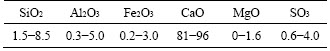
The static expansive agent which has been used in the market is more than 58 ��m grey powdery material composed of calcium carbonate and calcium oxide (Table 1). It will chemically react with water and rapidly set into cement when mixing with water. During the hydration reaction, the volume continues to increase. The average expansive stress can be up to 50 MPa if placed in sealed containers. The maximum duration of the hydration reaction is 6 h. The expansive stress test method of the static expansive agent is shown in Figure 1(a).
Table 1 Material component content of static expansive agent (wt%) [16, 32, 33]
The specific test steps are as follows:
1) Strain gauges are attached in the axial direction and the radial direction on the middle of the outer wall of a hollow steel pipe respectively.
2) One end of the hollow steel tube is sealed, and the static expansion agent that is evenly mixed with water is poured into it.
3) The other end of the hollow steel pipe is sealed, monitoring the axial and radial strain changes of the outer wall of the steel pipe during the hydration reaction of the static expansion agent.
Based on the monitored strain data, the variation of the expansive pressure in the steel pipe at different times is calculated by Eq. (1):
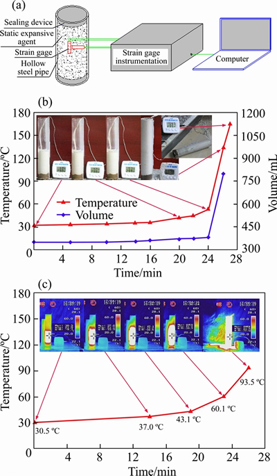
Figure 1 (a) Expansive pressure test principle; (b) Inside temperature and volume variation; (c) Temperature variation and distribution on surface
 (1)
(1)
where P is expansive pressure; ���� and ���� are the axial and radial strain of the outer wall of the steel pipe, respectively; E and �� are the elastic modulus and Poisson ratio of the steel pipe, respectively; t and r are the wall thickness and inner diameter of the steel pipe, respectively.
The temperature variation and volume expansion process are shown in Figure 1(b). When the ambient temperature is 23��C, the static expansive agent and water are mixed at a mass ratio of 3:1. The initial temperature of the static expansive agent after mixing with water is 32 ��C, and then it increases slowly to 57 ��C in the first 24 min. After that, the temperature increases rapidly with the volume of accelerating expansion. Because of the opening of the measuring cylinder, there is no limitation in the vertical direction for the volume expansion of the static expansive agent, and it swells up and fills the cylinder quickly. Finally, the agent erupts out from the container at 26 min with a temperature of 135 ��C. At 27 min, the temperature increases to 165 ��C. It can be seen from Figure 1(c), the maximum temperature at 0 min is 30.5 ��C, which is lower than the inside temperature of the static expansive agent. The variation trend of the surface maximum temperature monitored by the infrared radiometry is consistent with the inside temperature of the static expansive agent.
When fracturing with the static expansive agent in a single borehole, the static expansive agent is injected into it firstly. Then the borehole is sealed with a borehole packer. As the static expansive agent expands, it begins to squeeze the borehole wall. The stress evenly distributes around the borehole at the same depth, which is a function only of the radial variable, regardless of the azimuth (Figure 2(a)). The fracturing direction of the borehole wall is randomly distributed under the expansion pressure inside the single borehole. Finally, multiple fractures will be formed on the borehole wall (Figure 2(b)).
If there are two boreholes simultaneously fractured by the static expansive agent and the borehole spacing is small, the stress distribution area of adjacent boreholes will overlap, which is called superimposing of matrix stress. Stress increase zone occurs between boreholes, where the breaking occurs preferentially. Therefore, if a group of dense linear multi boreholes are drilled to perform expansive fracturing by pouring the static expansive agent into boreholes simultaneously (Figure 3(a)), a connected matrix stress concentration zone will be formed between the boreholes at the direction of boreholes layout. It can control the fracture initiation and propagation of each borehole.
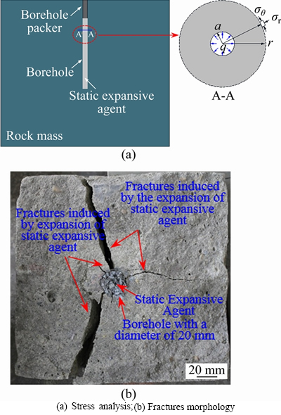
Figure 2 Multiple fractures induced by expansion of static expansive agent in single borehole:
The dense linear multi boreholes require no less than 3 boreholes, which are drilled in the same direction with the center of the boreholes in a straight line (Figure 3(a)). The borehole spacing must be smaller than the stress concentration range (usually refers to the range where stress is greater than 5% of the initial stress), which keeps the adjacent borehole within its stress concentration zone. The matrix stress concentration zone of adjacent holes will affect each other and be superimposed. Finally, a connected matrix stress concentration zone forms between the boreholes at the direction of boreholes layout. Matrix stress gradient will occur between the matrix stress concentration zone and in-situ stress zone, which will control the fracture initiation and propagation. The matrix stress gradient direction (Tangential tensile stress direction) is perpendicular to the direction of the boreholes layout. Therefore, the fracture initiation and propagation direction of each borehole will be along the direction of the boreholes layout. A directional fracturing plane will be formed (Figure 3(b)).
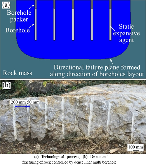
Figure 3 Technical process of directional fracturing with static expansive agent controlled by dense linear multi boreholes:
2.2 Technical process
The technological process of directional fracturing with static expansive agent controlled by dense linear multi boreholes is as follows. First, a group of dense linear multi boreholes are drilled into the rock. Then the static expansive agent is poured into the dense linear multi boreholes simultaneously through the equivalent diverter. Finally, each borehole is sealed by the sealing device or material, such as a borehole packer (Figure 3). The simultaneous expansion of the static expansive agent in dense linear multi boreholes induces the fractures between boreholes to propagate along the direction of boreholes layout. During the construction, the simultaneous injection of the static expansive agent into the multi boreholes and sealing effect of the borehole are important for ensuring the formation of a directional fracturing plane.
The principle of determining the spacing of boreholes is that for a given stress condition, lithology, and borehole diameter, the stresses of adjacent boreholes can superimpose on each other by adjusting the spacing of the boreholes after the boreholes squeezed. It induces cracks initiation and propagation along the direction of the borehole layout. Finally, the cracks intersect and connect. A directional rupture plane is formed. The spacing of the boreholes is related to the diameter of the borehole, the expansive pressure, the rock strength, and the stress condition. It needs to be determined according to the specific conditions during practical application. In the process of directional fracturing of the hard roof in underground coal mines, rapid drilling construction can be carried out with anchor rigs. The number of boreholes in a group can be 5-10 to perform the controlling directional fracturing.
3 Experiment
3.1 Experimental system and sample preparation
The experimental system mainly consists of a TS3890 strain gage instrumentation, a 24-channel acoustic emission monitoring, positioning inversion system, an R500 infrared radiometry, and a Digital Single Lens Reflex (Figure 4). The TS3890 strain gage instrumentation could measure and store static strain for multi-points. The 24-channel acoustic emission monitoring and positioning inversion system has an 18-bit A/D converter and frequency ranges of 1 kHz-3 MHz. It could store the waveform streaming data uniquely. The R500 infrared radiometry has a high resolution of 12��105 million pixels with a sensitivity of 0.03 ��C and an accuracy of ��1 ��C, which can measure the temperature range from -40 to 500 ��C. These devices are used to monitor the fracture initiation and propagation process in real-time, and detect the strain, acoustic emission and temperature changes in the surface and internal of the sample.
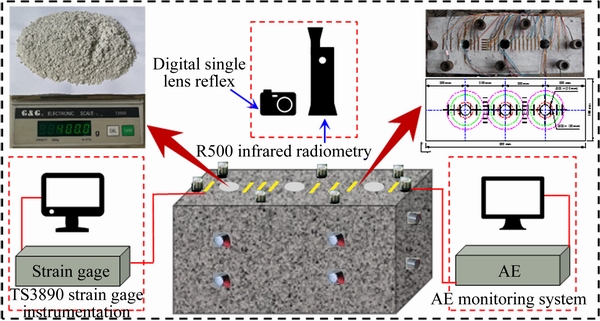
Figure 4 Schematic diagram of experimental system
The experimental sample is rectangular limestone with a dimensions of 800 mm��300 mm�� 400 mm. The physical and mechanical parameters are shown in Table 2. Three equidistance boreholes, 50 mm in diameter and 300 mm in length, are drilled vertically from the sample surface by the core bit. The boreholes spacing is 200 mm. The distance between the boreholes and the edge of the sample is 150 mm.
3.2 Experimental design
The monitoring program is the key to this experiment, which is carried out to monitor and record the crack initiation and propagation process, as well as the accompanying thermal effects and acoustic emission phenomena.
Table 2 Physical and mechanical parameters of limestone

The strain gauge is used to monitor the strain variation on the surface of the sample and the wall of the borehole. A total of 61 strain gauges are set on the surface of the sample, which includes two sets of orthogonal arrangements, one set along the direction of boreholes layout, and the other set perpendicular to the direction of boreholes layout. Four strain gauges are set on the wall of each borehole to monitor the axial strain and circumferential strain of the borehole wall (Figure 5). The strain gauge adopts the 1/4 bridge method, and the sampling frequency is set to 1 Hz.

Figure 5 Arrangement of strain gauge:
In this experiment, two different arrangements of the strain gauge are adopted to monitor the axial strain and circumferential strain respectively. The detailed placing process of axial strain gauge and circumferential strain gauge inside the borehole is as follows (Figure 6):
1) The signal wires to the strain gauge are welded.
2) The strain gauge and signal wire are glued on the adhesive tape. The other side of the strain gauge is coated with 502 Cyanoacrylate Glue. The adhesive tape isolates the strain gauge and signal wires from the static expansive agent inside the borehole, which can avoid the direct contact between strain gauges and static expansion agents. Meanwhile, the surface of the strain gauges is coated with 502 Cyanoacrylate Glue, which further reduces the temperature effect on strain gauges. As for the axial strain gauge, the length of adhesive tape is equal to the placing depth of the axial strain gauge. As for the circumferential strain gauge, the bottom part of adhesive tape attaching the strain gauge needs to be rotated 90�� to the horizontal direction. The vertical length of adhesive tape is equal to the placing depth of the circumferential strain gauge.
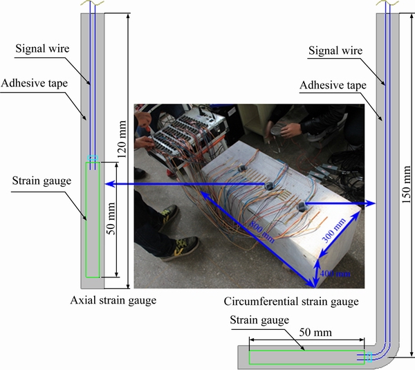
Figure 6 Placing of strain gauge on borehole wall
3) The adhesive tape is placed down to the designed position inside the borehole. Then a wooden stick is used to press the outside of the adhesive tape to paste it onto the borehole wall. Adhesive tape separates the strain gauge and signal wires from the static expansive agent inside the borehole during the experiment.
Meanwhile, 24-channel AE is used to record the acoustic emission signals during the directional fracturing with the static expansive agent. A total of 19 R15 AE sensors are arranged on the upper surface and four sides of the sample. All the gains of the preamplifiers are set to 60 dB. The sampling frequency is 5 MSPS (5��106 sample per second). R500 infrared radiometer and Digital Single Lens Reflex are set directly above the sample to monitor and record the temperature variation and fracturing process on the sample surface respectively. The sampling interval of the infrared radiometry is 3 s.
3.3 Experiment procedures
1) Installation of the monitoring system. The strain gauges are attached to the upper surface of the sample and the borehole wall. The signal wires of the strain gauges are connected with the strain gage instrumentation. The resistance value of strain gauges is measured by the AVO meter to ensure that the strain gauges work normally. The infrared radiometer and the Digital Single Lens Reflex are set directly above the sample. The AE sensors are placed on the upper surface and four sides of the sample.
2) Implementation of hydraulic fracturing. 4 kg of static expansion agent and 1.33 kg of water are weighed separately using high-precision electronic scales. Then they are poured into a container and mixed for 3-5 min until well mixed. After that, the static expansive agent is poured into three boreholes simultaneously. The boreholes are sealed by a metal plug and the corresponding fiber rod device, which is used to prevent the static expansive agent from spouting out from the boreholes. Meanwhile, there are grooves in the metal plug passing the signal transmission line so that it would not break the signal lines when sealing the borehole.
3) Fracturing process. The system time of the monitoring devices is set to be consistent. After setting the parameters, they are run to collect data synchronously. The static extensive agent inside the borehole continues to expand and induce the fractures to propagate to the surface of the sample.
4) Observation of hydraulic fracturing effect. The fractures morphology and fracturing plane morphology are observed and measured. The experiment is performed twice. As for the first time, the static expansive agent spouts out from the boreholes at 93 min because there is no presealing for the boreholes. The experiment paused. Additionally, it is not simultaneous when pouring the static expansive agent into the three boreholes. The No. 3 borehole is filled firstly; No. 2 and No. 1 borehole is followed sequentially. The difference pouring time of the static expansion agent causes the difference of stress in the three boreholes. There is the maximum stress in the No. 3 borehole. Consequently, only the No. 3 borehole was fractured, and two cracks are formed. One is along the direction of the borehole layout, and the other is perpendicular to it. The first experiment result shows that the static expansive agent can break the rock. However, the asynchrony of the stress effect acting on the wall of boreholes led to the asynchrony of crack initiation. Besides, it influences the superimposed effects of matrix stress, which increases the direction randomness of the fractures in the prior cracking borehole.
Some practical application learned from the first experiment is as follows. The static expansive agent should be injected into a group of the boreholes simultaneously through an equivalent splitter that connects the pump during the practical application. It synchronizes the hydration reaction of the static expansion agent in each borehole to improve the stress superposition coupling effect between the boreholes. Thereby, a better directional fracturing effect is achieved. The static expansive agent is mostly used in the cement broken in the actual engineering application process. Because the strength of cement is low, it can be broken without borehole sealing. When we carry out the first experiment, the borehole is not sealed. Due to the high strength of limestone, the expansive stress can not make it break. The static expansive agent is ejected from the borehole. Therefore, it is concluded that the borehole needs to be sealed when breaking high-strength rocks and other materials.
The residual static expansive agent in the remaining two boreholes is cleaned. The experiment is re-prepared, and a second experiment is performed. After it begins, the continuously increasing strain is monitored by the strain gauge. Many AE signals with big amplitudes are escalated after 5 h. At this time, the micro-fractures appear on the sample surface. The experiment is terminated after 6 h.
4 Results and discussion
4.1 Fracture initiation and propagation
As the static expansive agent slowly expands, the borehole wall deforms under the expansive pressure (Figure 7). During the experiment, the tensile strain is generated both in the axial and circumferential directions of the borehole��s wall. It indicates that the wall of the borehole is continuously subjected to tensile stress during the expansion of the static expansive agent. In the first 100 min, there are slow changes in the strain of the borehole��s wall. The tensile strain in the axial and circumferential directions grows linearly. While the stain in the axial direction is bigger than that in the circumferential direction. After 100 min, the circumferential strain ��B1 of the No.1 borehole begins to increase rapidly. Finally, the strain gauge fails at 145 min with a strain of 8913�̦�. In this process, the axial strain ��A1 of the No.1 borehole still maintains a uniform growth rate.
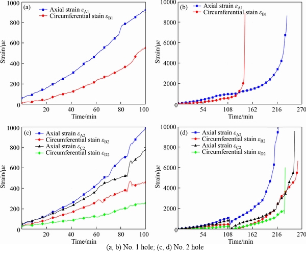
Figure 7 Strain variation monitored by strain gauge during experiment:
The growth rate increases at 180 min. The strain reaches 8649�̦� at 237 min, and the strain gauge fails (Figure 7(b)). The other two strain data of the No. 1 hole are not measured due to the problems with strain gauges. In the No. 2 borehole, the strain is 458�̦�, 988�̦�, 257�̦�, 776�̦�, respectively at 100 min. The strain gauge is abnormal at 112 min with the strain value becoming negative, and then gradually rises. The growth rate of circumferential strain ��A2 gradually increases after 210 min and fails at 260 min as strain increases to 6680�̦�. The axial strain ��B2 begins to increase rapidly at 180 min, and the strain gauge B2 fails at 218 min with a strain of 9950�̦�. The circumferential strain ��C2 increases rapidly at 230 min and fails after 3 min as strain increases from 1865 to 6040�̦�. The growth rate of axial strain ��D2 gradually increases after 210 min and fails at 253 min as strain increases to 9596�̦� (Figure 7(d)). The phenomenon that the four groups of strain data in No. 2 hole drops sharply at about 110 min may due to the problem of the strain gauge instrumentation system. Since the static expansive agent is not poured into the three boreholes simultaneously in the first experiment, the expansive pressure acting on the three boreholes is different. It results in the strength damage difference for the surrounding rock around the No. 1 hole and No. 2 hole. This may be the reason why the strain variation of No. 1 and No. 2 holes is different.
The hydration reaction of the static expansive agent is gentle, and the volume expands slowly in the first 100 min. Therefore, the expansive pressure acting on the borehole wall is small, which causes the slow and uniform deformation of it. The hydration reaction of the static expansive agent is gradually vigorous after 100 min with the volume expansion speed accelerates. It leads to a rapid increase of the expansive pressure. The direction of the boreholes layout is always the direction of peak tangential tensile stress due to the superimposing of the matrix stress between the borehole. As the expansion stress increases, the peak values of tangential tensile stress also increase. When it reaches the tensile strength of the sample, the boreholes wall will initially fracture along the direction of the borehole layout.
The strain on the sample surface between boreholes and associated AE signal during the experiment are shown in Figure 8. According to the variation of strain and the distribution of associated AE event and energy, the experiment can be divided into the following three stages. The first stage is from 0 to 175 min. The second stage is from 175 to 300 min. The third stage is from 300 to 325 min. The hydration reaction of the static expansive agent is gentle, and the volume expands slowly in the first stage. The detected strain has a little variation, and there are very few AE event count and almost no energy release. The strain on the sample surface begins to rise in the second stage. This process is accompanied by increasing of AE event count and cumulative event account. AE energy reaches a high level. These indicate that the tensile strength of the sample is reached and some initial micro-fracturing occurs inside the sample. The strain increases rapidly in the third stage. The high-density AE signals are recorded with very high energy content. The AE cumulative event count and AE cumulative energy versus time curves show a sharp rise. These behaviors indicate that some wide range of fractures occurs inside the sample. The internal micro-fracturing planes are connected to form a macro-fracture. Finally, it propagates to the surface of the sample.
Strain gauges A-F are arrayed between boreholes along the direction of boreholes layout (Figure 5). The monitored strain indicates that the tensile strain occurs perpendicular to the direction of boreholes layout. Strains gauges 1-7 are arrayed at the center between boreholes and perpendicular to the direction of boreholes layout (Figure 5). The monitored strain indicates that the compressive strain occurs along the direction of boreholes layout. Besides the closer to the boreholes, the greater the compression strain.
The temperature distribution on the upper surface of the sample during the experiment is shown in Figure 9. The hydration reaction process of the static expansive agent is exothermic. The amount of heat release increases constantly after the reaction begins. When the heat released by the reaction is greater than the heat loss, the internal temperature of the borehole gradually increases. The heat transfers around the borehole, which causes the temperature around the borehole wall to rise. A circular heat transfer zone centered on the borehole is formed around each borehole. The heat (temperature) attenuates gradually outward from the borehole wall. As the temperature constantly increases inside the borehole, the heat transfer area expands continuously. It causes the heat transfer area between boreholes connected and overlapped. Finally, a connected-high temperature zone is formed in the direction of boreholes layout, which will enhance the directional fracturing of the rock at the direction of borehole layout.
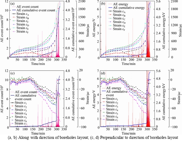
Figure 8 Strain on sample surface between boreholes and associated AE signal during experiment:
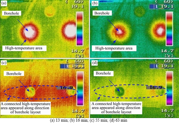
Figure 9 Temperature distribution on sample surface during experiment at rent time:
After the initial fracturing of the boreholes, the fractures continue to propagate under the expansive pressure. Since the expansion process of the static expansive agent is relatively slow, the expansive pressure does not directly act on the fractures surface. The fracture propagating rate is slower than that of the fluid-driven fractures. The real-time monitoring of the camera shows that the sample initially fractures on the right side of No. 2 borehole at 302 min where a fracture occurs along the direction of boreholes layout. It gradually opens and continues to propagate along the initial direction. Afterward, a fracture occurs between boreholes and gradually propagates to No. 1 borehole. Finally, it extends to the left edge of the sample. A connected fracture is formed in the direction of boreholes layout (Figure 10). The sample initially fractures from the right side, instead of between the boreholes. It relates to the first experiment. As mentioned above, since the static expansive agent is not poured into the three boreholes simultaneously in the first experiment, the expansive pressure acting on the three boreholes is different. At the same time, strength damage to the surrounding rock around the No. 3 borehole is more serious than the other two boreholes. Before the start of the second experiment, the sample strength on the right side is weaker than that on the left side. If the static expansive agent is poured into the boreholes simultaneously, the final directional fracturing effect will be better.
4.2 Opening and fracture
The fractures between boreholes propagate towards each other and form a connected directional fracturing plane under the superimposing of matrix stress (Figure 11(a)). At this time, the opening of the fracture is small. Some rock particles still bond to each other inside the fracture plane. Therefore, it still has a certain residual bond strength. However, the residual strength of the fracture plane is much smaller than the tensile strength of the sample. With the continuous action of the static expansive agent,the fracture plane is completely connected. The opening gradually increases (Figures 11(b) and (c)). The final opening of the fracture is 45 mm (Figure 11(d)).
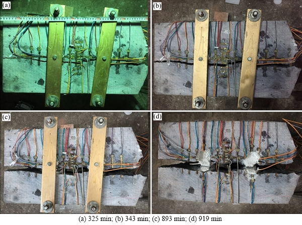
Figure 10 Real-time propagation of fracture:
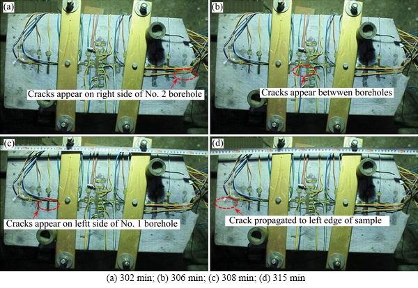
Figure 11 Opening of surface fracture:
The size of the fracture opening reflects the expansion property of the static expansive agent. The larger the fracture opening, the higher the volume expansion ratio of the static expansive agent. Finally, the diameter of the expansion borehole in the direction perpendicular to the fracture is 545 mm. The volume expansion ratio of the static expansive agent is about 9%. A directional fracture is formed inside the sample along the direction of the boreholes layout. The fracture propagates to the surface of the sample. A better directional rupture effect is achieved.
4.3 Roughness in surface of fracture
The shape of the fracture on the upper surface of the sample is shown in Figure 12. The fracture does not pass through the center of the borehole, which indicates that the crack experiences a polyline propagation process after the initial fracturing inside the sample. However, the overall propagation is still along the direction of boreholes layout. Meanwhile, when propagated towards each other, the fractures deflect slightly in space. Finally, the fractures connect in the form of a polyline.
The overall morphology of the fracture surface is shown in Figure 13(a). It presents a relatively smooth plane with little bias but much local fluctuation (Figure 13(b)), which divides the sample into symmetrical two parts along the direction of the boreholes layout. The static expansive agent is a solid material and does not have the fluidity of the fluid. It cannot flow inside the fracture with the fracture propagation. Therefore, there is no ��water-wedge effect�� that can cause a stress concentration at the tips of fracture. As a result, the low-stress concentration makes the fracture deflect more during the propagation than hydraulic fracture. The randomness of fracture propagation direction increases. Meanwhile, the fracture propagates slowly and the fracturing range each time at the fracture tip is small due to the slow expansion characteristics of the static expansive agent. So, fracture propagation direction does not show larger bias range. The overall propagation direction is mainly affected by the superimposing of matrix stress between dense linear multi boreholes, which causes the fracture initiation and propagation along the direction of the boreholes layout.
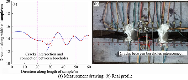
Figure 12 Edge profile of fracture:
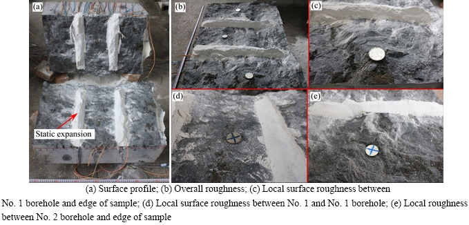
Figure 13 Surface profile and roughness:
4.4 Mechanism of directional fracturing using static expansive agent
During the directional fracturing with the static expansive agent in dense linear multi boreholes, the fracture initiation and propagation direction of each borehole are controlled by the superimposing of matrix stress between dense linear multi boreholes. As the static expansive agent slowly expands, the borehole wall deforms under the expansive pressure. A matrix stress increase zone is formed in the surrounding rock. By controlling the borehole spacing, the matrix stress is superimposed between boreholes. The tangential tensile stress occurs between boreholes and increases with the expansive pressure increasing. Besides, the closer the distance from the borehole wall, the greater the tangential tensile stress. The superimposing of matrix stress between boreholes makes the maximum effective tangential tensile stress tend to be along the direction of the boreholes layout. When the effective tangential tensile stress at the boreholes wall caused by the hydration reaction of the static expansive agent reaches the tensile strength of the rock, the boreholes wall initially fracture along the direction of the boreholes layout. After the initial fracturing, the fractures continue to propagate under the effect of expansive pressure. The initial fractures created by the directional fracturing guide the subsequent propagation of fractures. Meanwhile, the superimposing of the matrix stress between the boreholes makes the direction of boreholes layout always be the direction of peak tangential tensile stress. Therefore, the fractures between the boreholes tend to propagate in the direction of the boreholes layout during the propagation process. Finally, fractures intersect and connect and a directional rupture plane forms.
Some parameters can be controlled to influence the fracture initiation and propagation of directional fracturing controlled by dense linear multi boreholes, such as the three-dimensional in-situ stress, the difference of the principal stress, the angle between borehole layout, the minimum principal stress, the radio of borehole spacing, borehole diameter, and lithology (homogeneity). The future work will focus on these parameters.
5 Conclusions
1) The directional fracturing method with static expansive agent controlled by dense linear multi boreholes takes the superposition of matrix stress between dense linear multi boreholes into account. It results in a connected tangential tensile stress concentration zone between boreholes along the direction of boreholes layout, where the fracturing occurs preferentially.
2) Due to the superimposing of the matrix stress between the dense linear multi boreholes, the direction of the boreholes layout is always the direction of peak tangential tensile stress. Besides, the tangential tensile stress along this direction is preferential to reach the tensile strength of the rock, which ensures the fractures to preferentially initiate and propagate in the direction of the boreholes layout. Finally, the fractures intersect and connect and a directional rupture plane forms.
3) According to the variation of strain and the distribution of associated AE events and energy, the experiment can be divided into three stages. The static expansive agent expands slowly with no fracturing inside the rock in the first stage. Some initial micro-fracturing occurs inside the rock in the second stage. A wide range of fracturing occurs inside the sample in the third stage. The internal micro-fracturing plane connects to form a macro-fracture. Finally, it propagates to the surface of the rock.
4) Through directional fracturing with static expansive agent controlled by the dense linear multi boreholes, a directional fracture is formed inside the sample along the direction of the boreholes layout. The fracture propagates to the surface of the sample and a better directional rupture effect is achieved. The directional fracturing plane presents a relatively smooth plane with little bias but much local fluctuation.
Contributors
HUANG Bing-xiang put forward the idea. ZHAO Xing-long designed the experiment. ZHAO Xing-long, WANG Chang-wei and CHEN Shu-liang carried out the experiment. ZHAO Xing-long, CHENG Qing-ying and WANG Chang-wei performed data processing and analysis, and contributed to the paper writing. HUANG Bing-xiang offered some valuable suggestions for the contents of the manuscript. All authors replied to reviewers�� comments and revised the final version.
Conflict of interest
ZHAO Xing-long, HUANG Bing-xiang, CHENG Qing-ying, WANG Chang-wei, and CHEN Shu-liang declare that they have no conflict of interest.
References
[1] WANG Han-jun, HUANG Feng-lei, ZHANG Qing-ming. Mechanics effect analysis and parameters study on borehole directional fracture blasting [J]. Journal of China Coal Society, 2003, 28(4): 399-402. DOI: 10.13225/j.cnki.jccs.2003. 04.014. (in Chinese)
[2] LIU Ke-wei, LI Xiao-han, LI Xi-bing, YAO Zhi-hua, SHU Zong-xian, YUAN Ming-hua. Characteristics and mechanisms of strain waves generated in rock by cylindrical explosive charges [J]. Journal of Central South University, 2016, 23(11): 2951-2957. DOI: 10.1007/s11771-016-3359-7.
[3] ZHANG Xing-yu, PAK R Y S, GAO Yu-bing, LIU Chen-kang, ZHANG Cheng, YANG Jun, HE Man-chao. Field experiment on directional roof presplitting for pressure relief of retained roadways [J]. International Journal of Rock Mechanics and Mining Sciences, 2020, 134: 104436. DOI: 10.1016/j.ijrmms. 2020.104436.
[4] YANG Ren-shu, TONG Qiang, YANG Guo-liang. Presplitting blasting with binding energy tube charges: simulations and experimental research [J]. Journal of China University of Mining & Technology, 2010, 39(5): 632-635. (in Chinese)
[5] HE Man-chao, CAO Wu-fu, SHAN Ren-liang, WANG Shu-li. New blasting technology��bilateral cumulative tensile explosion [J]. Chinese Journal of Rock Mechanics and Engineering, 2003, 22(12): 2047-2051. (in Chinese)
[6] JENDRYS M, HADAM A, CWIEKALA M. Directional hydraulic fracturing (DHF) of the roof, as an element of rock burst prevention in the light of underground observations and numerical modelling [J]. Energies, 2021, 14(3): 562. DOI: 10.3390/en14030562.
[7] CHENG Yu-gang, LU Zhao-hui, DU Xi-dong, ZHANG Xue-fu, ZENG Meng-ru. A crack propagation control study of directional hydraulic fracturing based on hydraulic slotting and a nonuniform pore pressure field [J]. Geofluids, 2020: 8814352. DOI: 10.1155/2020/8814352.
[8] LEKONTSEV Y M, SAZHIN P V. Application of the directional hydraulic fracturing at Berezovskaya Mine [J]. Journal of Mining Science, 2008, 44(3): 253-258. DOI: 10.1007/s10913-008-0015-0.
[9] HUANG Bing-xiang, YU Bin, FENG Feng, LI Zhao, WANG You-zhuang, LIU Jin-rong. Field investigation into directional hydraulic fracturing for hard roof in Tashan Coal Mine [J]. Journal of Coal Science & Engineering, 2013, 19(2): 153-159. DOI: 10.1007/s12404-013-0208-2.
[10] MONJEZI M, REZAEI M, YAZDIAN A. Prediction of backbreak in open-pit blasting using fuzzy set theory [J]. Expert Systems with Applications, 2010, 37(3): 2637�C2643. DOI: 10.1016/j.eswa.2009.08.014.
[11] HASANIPANAH M, ARMAGHANI D J, MONJEZI M, SHAMS S. Risk assessment and prediction of rock fragmentation produced by blasting operation: A rock engineering system [J]. Environmental Earth Ences, 2016, 75(9): 1-12. DOI: 10.1007/s12665-016-5503-y.
[12] HUANG Bing-xiang, WANG You-zhuang. Field investigation on crack propagation of directional hydraulic fracturing in hard roof [J]. Journal of China Coal Society, 2015, 40(9): 2002-2008. DOI: 10.13225/j.cnki.jccs.2014.1646. (in Chinese)
[13] RAHMAN M K, JOARDER A H. Investigating production-induced stress change at fracture tips: Implications for a novel hydraulic fracturing technique [J]. Journal of Petroleum Science & Engineering, 2006, 51(3): 185-196. DOI: 10.1016/j.petrol.2005.12.009.
[14] RADHIKA V D S, RANJITH P G, MANDADIGE S A P. An alternative to conventional rock fragmentation methods using SCDA: A review [J]. Energies, 2016, 9(11): 958-989. DOI: 10.3390/en9110958.
[15] DESSOUKI A E, MITRI H. Rock breakage using expansive cement [J]. Engineering, 2011, 3(2): 168-173. DOI: 10.4236/ eng.2011.32020.
[16] LAEFER D F, ABROZEVITCH-COOPER N, HUYNH M P. Expansive fracture agent behaviour for concrete cracking [J]. Magazine of Concrete Research, 2010, 62(6): 443-452. DOI: 10.1680/macr.2010.62.6.443.
[17] SOEDA K, HARADA T. The mechanics of expansive pressure generation using expansive demolition agent [J]. Doboku Gakkai Ronbunshu, 2010, 466: 89-96. DOI: 10.2208/jscej.1993.466_89.
[18] HINZE J, BROWN J. Properties of soundless chemical demolition agents [J]. Journal of Construction Engineering & Management, 1994, 120(4): 816-827. DOI: 10.1061/(ASCE) 0733-9364(1994)120:4(816).
[19] NOCUN-WCZELIK W, STOK A, KONIK Z. Heat evolution in hydrating expansive cement systems [J]. Journal of Thermal Analysis & Calorimetry, 2010, 101(2): 527-532. DOI: 10.1007/s10973-010-0846-1.
[20] NATANZI A S, LAEFER D F, CONNOLLY L. Cold and moderate ambient temperatures effects on expansive pressure development in soundless chemical demolition agents [J]. Construction and Building Materials, 2016, 110: 117-127. DOI: 10.1016/j.conbuildmat.2016.02.016.
[21] GAMBATESE J A. Controlled concrete demolition using expansive cracking agents [J]. Journal of Construction Engineering & Management, 2003, 129(1): 98-104. DOI: 10.1061/(ASCE)0733-9364(2003)129:1(98).
[22] DOWDING C H, LABUZ J F. Fracturing of rock with expansive cement [J]. Journal of the Geotechnical Engineering, 1982, 108(10): 1288-1299. DOI: 10.1061/ AJGEB6.0001353.
[23] GOMEZ C, MURA T. Stresses caused by expansive cement in borehole [J]. Journal of Engineering Mechanics, 1984, 110(6): 1001-1005. DOI: 10.1061/(ASCE)0733-9399(1984) 110:6(1001).
[24] MAMBOU N L L, GAEL N C. Numerical study of stresses around holes drilled and filled by expansive cement: case of isotropic linear elastic block of rock [J]. Advances in Materials Science and Engineering, 2018: 1-14. DOI: 10.1155/2018/ 8718452.
[25] GUO Tian-kui, ZHANG Shi-cheng, GE Hong-kui, WANG Xiao-qiong, XIAO Bo. A new method for evaluation of fracture network formation capacity of rock [J]. Fuel, 2015, 140: 778-787. DOI: 10.1016/j.fuel.2014.10.017.
[26] GUO Tian-kui, ZHANG Shi-cheng, GE Hong-kui. A novel ��soundless cracking agent fracturing�� for shale gas reservoir stimulation [J]. International Journal of Environmental Science and Development, 2015, 6(9): 681-687. DOI: 10.7763/IJESD.2015.V6.680.
[27] ANAND M, HANI M. Laboratory investigation into rock fracturing with expansive cement [J]. International Journal of Mining and Mineral Engineering, 2009, 1(4): 327. DOI: 10.1504/IJMME.2009.029318.
[28] RADHIKA V D S, RANJITH P G, MANDADIGE S A P. A low energy rock fragmentation technique for in-situ leaching [J]. Journal of Cleaner Production, 2018, 204: 586-606. DOI: 10.1016/j.jclepro.2018.08.296.
[29] HAO Bing-yuan, HUANG Hui, FENG Zi-jun, WANG Kai. The static breaking technique for sustainable and eco-environmental coal mining [J]. The Scientific World Journal, 2014: 248792. DOI: 10.1155/2014/248792.
[30] TANG Shi-bin, HUANG Run-qiu, WANG Shan-yong, BAO Chun-yan, TANG Chun-an. Study of the fracture process in heterogeneous materials around boreholes filled with expansion cement [J]. International Journal of Solids and Structures, 2017, 112: 1-15. DOI: 10.1016/j.ijsolstr.2017.03. 002.
[31] CHENG Qing-ying, HUANG Bing-xiang, ZHAO Xing-long. Numerical investigation on the mechanism of rock directional fracturing method controlled by hydraulic fracturing in dense linear multiholes [J]. Shock and Vibration, 2020: 6624047. DOI: 10.1155/2020/6624047.
[32] HARADA T, SOEDA K, IDEMITSU T, WATANABE A. Characteristics of expansive pressure of an expansive demolition agent and the development of new pressure transducers [C]// Japan Society of Civil Engineers. Tokyo, Japan, 1994. DOI: 10.2208/jscej.1993.478_91.
[33] HUYNH M P, LAEFER D F. Expansive cements and soundless chemical demolition agents: State of technology review [C]// Proceedings of the 11th Conference on Science and Technology. Ho Chi Minh City, Vietnam: 21�C23, October, 2009.
(Edited by ZHENG Yu-tong)
���ĵ���
�ܼ����Զ�������Ͷ������ѵĻ�������
ժҪ���������������ʯ�����еĹؼ�����֮һ������������ܼ����Զ�������Ͷ������ѷ�����ͨ���������������ܼ����ĹǼ�Ӧ������������ã���ʹ���ѵ��ѷ���������ߵ����߷����ͨ�γɶ��������棬ʵ����ʯ�Ķ������ѡ�����ʯ���������������ܼ����Զ�������Ͷ�������ʵ�飬�о����ܼ����Զ�������Ͷ������ѵĻ������ɡ�ʵ����������ͨ���ܼ����Զ�����������ѣ���������߷����γ��˶��������档�������ѹ����е�Ӧ�估��Ӧ���������¼������������ѹ��̿��Է�Ϊ�����Ρ��ڵ�һ�Σ��������ͼ��������ͣ���ʯ�ڲ�û�����Ѳ������ڵڶ��Σ���ʯ�ڲ��������ѣ��ڵ����Σ���ʯ�ڲ����ֽϴ�Χ�����ѣ���ʼ���ѷ����ͨ�γɺ�������棬����չ���������档�����ѷ���������Ϊƽ�����ֲ�����ϴ�
�ؼ��ʣ��������ѣ��������ͼ����Ǽ�Ӧ�����ӣ��������ѣ��ѷ���չ
Foundation item: Project(2017YFC0603001) supported by the National Key Research and Development Program of China; Projects(51774272, 52004269) supported by the National Natural Science Foundation of China; Project(2019M661995) supported by the China Postdoctoral Sciences Foundation
Received date: 2020-08-06; Accepted date: 2021-03-23
Corresponding author: HUANG Bing-xiang, PhD, Professor; Tel: +86-13585398762; E-mail: huangbingxiang@cumt.edu.cn; ORCID: https://orcid.org/0000-0003-3399-0285
Abstract: Directional rupture is one of the difficult problems in deep rock mechanics and engineering. A directional fracturing method with static expansive agent controlled by dense linear multi boreholes is proposed. A physical experiment is designed and performed to investigate the basic laws of this method. The fracture initiation and propagation process, and the mechanism of directional fracturing are analyzed. The results indicate that a directional fracture is formed along the direction of boreholes layout through directionally fracturing with static expansive agents controlled by the dense linear multi boreholes. According to the variation of strain and the distribution of associated acoustic emission (AE) events and energy, the experiment can be divided into three stages. In the first stage, the static expansive agent expand slowly with no fracturing inside the rock. In the second stage, some initial micro-fracturing occurs inside the rock. In the third stage, a wide range of fracturing occurs inside the sample. The internal micro-fracturing planes are connected to form a macro-fracture. Finally, it propagates to the surface of the sample. The directional fracturing plane presents a relatively smooth plane with little bias but much local fluctuation.
