

FEM simulation of aluminum extrusion process in porthole die with pockets
HE You-feng(���ŷ�), XIE Shui-sheng(лˮ��), CHENG Lei(�� ��),
HUANG Guo-jie(�ƹ���), FU Yao(�� ��)
State Key Laboratory for Fabrication and Process of Nonferrous Metals,
General Research Institute for Nonferrous Metals, Beijing 100088, China
Received 8 July 2009; accepted 24 September 2009
Abstract:
In order to investigate the effects of pockets in the porthole die on the metal flow, temperature at the die bearing exit and the extrusion load were contrasted with the traditional die design without the pockets in the lower die. Two different multi-hole porthole dies with and without pockets in lower die were designed. And the extrusion process was simulated based on the commercial software DEFORM-3D. The simulation results show that the pockets could be used to effectively adjust the metal flow and especially benefit to the metal flow under the legs. In addition, the maximum temperature at the die bearing and the peak extrusion load decrease, which indicates the possibility of increasing the extrusion speed and productivity.
Key words:
FEM simulation; aluminum; extrusion; porthole die; die design;
1Introduction
In aluminum extrusion process, die structure (bearing length, shape and dimension of pocket cavity and welding chamber) and processing parameters (extrusion temperature, velocity, die and container preheating temperature, and etc) have great effect on the quality of final products. In addition, the multi-hole die sometimes may also be used to avoid a high reduction ratio and can improve the maximum productivity. For some special solid profiles with large cantilever, it may need the porthole and pocket die extrusion, which increases much more design difficulties. For these complicated influencing factors, in practical die design, traditional ��try-and-error�� method is always used, which is costly and wastes production time.
In multi-hole porthole die extrusion process, it is a challenging task for the die designer to control the flow velocity at the die bearing exit by intuition and experiences due to the complex influencing factors, such as the sizes and shape of the profiles, the number and layout of die orifices, bearing length under the legs and welding chamber shape, in addition to operational extrusion processing parameters such as extrusion temperature and speed. In the past, many researchers have investigated extrusion die design using methods such as physical modeling method[1-3], theoretical analysis method[4] and the more recently developed finite element method (FEM)[5-9] which has, however, been proven to be a powerful tool and capable of predicting the metal flow during multi-hole porthole die extrusion process. FANG et al[10] did the multi-hole pocket dies FEM simulation and extrusion experiments, and found that multi-steps in die pocket could be effectively used to regulate the metal flow through multi-hole dies. LI et al[11-12] also investigated the influence of pocket die (the pocket angle, volume and pocket geometry configurations) design on metal flow in aluminum extrusion based on 2D FEM simulation. CHENG et al [13] and JO et al[14] analyzed the extrusion process of the harmonica-shaped tube and Al round tube respectively using non-steady state FEM simulation. However, few researches about extrusion process on porthole die with pockets in the welding chamber were investigated by means of FEM simulation.
The aim of this study was to understand the non-steady state extrusion process based on the FEM simulation, the behavior of metal flow, the extrusion load, the velocity field and so on were obtained, which is useful to optimize the die design. The updated Lagrangian approach in DEFORM 3D software was used to simulate the two ��H�� shape profiles with a small cantilever through two-hole porthole die with two different designs.
2 Die design
Fig.1(a) shows the cross-section shape and dimensions of the aluminum profile used in the present case study. It is a typical architectural profile with small cantilever (location A as shown in Fig.1(a), and the width is only 2.0 mm), small grooves of 0.45 mm (location B as shown in Fig.1(a)) and thickness of 1.0 mm. If the flat or pocket die with one hole was adopted, the plastic deformation of the die would be severe, and the strength of small cantilever can easily yield for high extrusion ratio. So, in order to avoid the direct force of metal flow to the small cantilever and reduce the plastic deformation of the die, two-hole porthole die with no mandrel was designed, as shown in Fig.2. In this die design, the two orifices in the die may be positioned symmetrically, as shown in Fig.1(c), for better adjustment of flow uniformity and synchronization relatively easily. The small cantilevers were under the legs; and the separated upper welding chambers (with height of 20 mm) were used. In addition, the extrusion ratio was down to 65 when the diameter of the container was 160 mm.
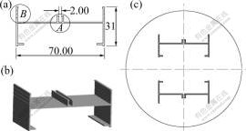
Fig.1 Cross-section shape of extrudate (a), 3D solid model (b) and symmetrical layout of die orifices (c)
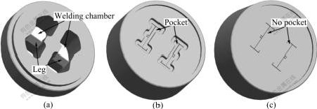
Fig.2 Porthole die with and without pocket: (a) Upper die; (b) Lower die with pocket; (c) Lower die without pocket
3 FEM simulationThe extrusion of 6061 aluminum alloy through the porthole die with and without pocket was simulated using the commercial software package DEFORM 3D. The 3D assembly models and meshes used in the simulation are shown in Fig.3. The FE simulation was carried out with 1/4 section of the billet and porthole die because of the symmetrical structure, which can save computer RAM source and computation time. The rigid-visco-plastic deformation behavior of the billet with thermal effects incorporated was used in this simulation. The die and other extrusion tooling were assumed to be rigid and made of the H13 tool steel.
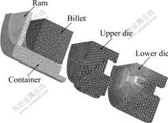
Fig.3 Die assembly models and meshes used in FEM simulation
In the hot extrusion process, friction among the container, die and billet has influenced the extrusion load, extrudate temperature and metal flow at the die bearing exit. Because of high temperature and the pressure in container and die, the exact friction mechanisms involved in the process have not been thoroughly understood and mathematically expressed. At present, it has been acknowledged as the most uncertain parameter in the FEM simulation of aluminum extrusion. In the present research, the shear friction model was assumed to represent the friction among the billet, die and container:
fs=mk (1)
where fs is the friction stress, k is the shearing yield stress and m is the friction factor. In practical aluminum hot extrusion, no lubrication is applied among the billet, container and die. Accordingly, a friction factor of 0.8 was assumed at the billet-container and die interface for being highly sticky, while a friction factor of 0.4 was assumed at the die bearing interface to represent the sliding contact between billet and die bearing[15]. The extrusion parameters used in FEM simulation as well as the friction factors specified are given in Table 1.
Table 1 Process parameters and friction factors used in FEM simulation

4.1 Metal flow and velocity distribution
Metal flow in the porthole die extrusion with pockets is a highly complex process for the complicated die structure. Fig.4 shows the extrusion process that the billet material takes from entering the porthole to emerging from the lower die orifices. At first, the billet is upset in the container and flows into the portholes as shown in Fig.4(a); then the billet is divided into several metal flows through the portholes as shown in Fig.4(b); thirdly, the metal flows merge in the welding chamber and pocket as shown in Fig.4(c); finally, the extrudate emerges from the die bearing and then approaches the steady state as shown in Fig.4(d). However, when the lower die without pocket is used, the metal flows will be extruded directly from the bearing after flowing through the portholes.
For better illustrating the effect of the porthole die with pocket on the velocity distribution at the die orifices, two sets of die design structure were simulated. Fig.5 shows the contrast of the velocity distribution between the die design with or without the pockets under the same extrusion processing and die bearing length. It can be seen from Fig.5 that the metal at the two sides of the profiles flows faster than in the other areas. This is because the centre of the profiles is under the legs of the die, so the metal velocity tends to decrease toward the center. If the lower die has pocket, the velocity will be more uniform, and the metal flows under the legs increase resulted from the pre-adjustment of the metal flows by the pockets. Thus, the even forepart is obtained as shown in Fig.5(b).
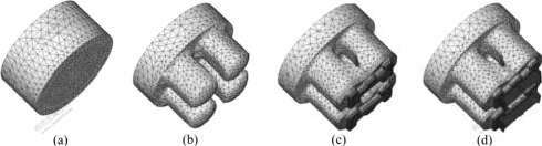
Fig.4 Metal flow through porthole die with pocket: (a) Upsetting container; (b) Dividing; (c) Welding and filling pocket; (d) Flowing out of orifices
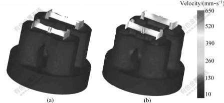
Fig.5 Contrast of velocity distribution at bearing exit: (a) Lower die without pocket; (b) Lower die with pocket
4.2 Temperature
The extrudate temperature at the die bearing exit is the most important parameter, which determines the surface quality of the product and the possibility of increasing extrusion speed. High temperature may lead to local recrystallisation and grain growth possibly forming the coarse grain circle, which is detrimental to the mechanical properties of the extruded product. It is therefore necessary to contrast the temperature distribution and evaluate the effect of pocket design on the extrudate temperature at the die bearing exit.
Fig.6 shows the temperature distribution of extrudate through the lower die with and without pocket. The maximum temperatures appear at the die bearing exit of the lower die without pocket, due to severe plastic deformation and friction at the interface between the metal and die bearing as shown in Fig.6(a). While the metal flows out of the die bearing and are exposed to the ambient temperature, the extrudate is cooled by air and thus the front part of the profiles has lower temperature. However, the temperatures of the lower die with pocket are quite homogeneous as shown in Fig.6(b). The reasons reasons for this influence are that metal flows more easily from the portholes to the die bearing due to the pre-deformation of the pocket and increases the contact area and time between the billet and the die pocket, leading to more heat dissipation into the initially colder die. Thus, this decreases the extrudate temperature at the die bearing exit by about 40-50 �� compare with the lower die without the pockets, which indicates the possibility of increasing extrusion speed and therefore increases the productivity.
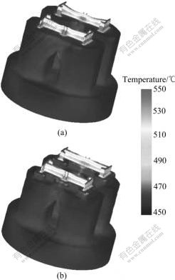
Fig.6 Contrast of extrudate temperature distribution at bearing exit: (a) Lower die without pocket; (b) Lower die with pocket
4.3 Extrusion load
In extrusion die design, the predicted extrusion load is important for assessing the capability of the press machine. It is therefore necessary to predict the extrusion load due to adding the pockets in the lower die, resulting in the increasing contact area and friction between the billet and extrusion die, which will be possible to increase the extrusion load. However, Fig.7 shows that the extrusion load decreases while adding the pockets in the lower die. This indicates that although the contact area increases the friction due to the pockets, easier metal flow and smaller dead metal zone lead to a lower extrusion load. Clearly, the two drawing curves are almost the same before the metal reaches the bottom of lower die, then, the extrusion load increases quickly with the ram moving and reaches the maximum value while the metal flows through the die bearing, at last reaches a steady state. The lower die with pocket delays the extrusion load increase due to the metal filling the pocket first.
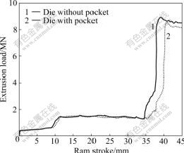
Fig.7 Extrusion load��ram displacement curves of lower die with and without pockets
5 ConclusionsThe performance of the lower die with pockets in multi-hole porthole die extrusion of a profile was investigated using 3D FEM simulation, in comparison with that of the lower die without pockets. It is confirmed that pockets in lower die play an important role, such as more even metal flow and plastic deformation, lower temperature rise at the bearing exit and lower peak extrusion load, which is beneficial to the extrusion process.
References
[1] KIM Y T, IKEDA K, MURAKAMI T. Metal flow in porthole die extrusion of aluminum [J]. Journal of Materials Processing Technology, 2002, 121: 107-115.
[2] UYYURU R K, VALBERG H. Physical and numerical analysis of the metal flow over the punch head in backward cup extrusion of aluminum [J]. Journal of Materials Processing Technology, 2006, 172: 312-318.
[3] GOUVEIA B P P A, RODRIGUES J M C, MARTINS P A F, BAY N. Physical modeling and numerical simulation of the round-to-square forward extrusion [J]. Journal of Materials Processing Technology, 2001, 112: 244-251.
[4] XIE J X, IKEDA K, MURAKAMI T. UBA analysis of the process of pipe extrusion through a porthole die [J]. Journal of Materials Processing Technology, 1995, 49: 371-385.
[5] SINHA M K, DEB S, DIXIT U S. Design of a multi-hole extrusion process [J]. Materials & Design, 2009, 30(2): 330-334.
[6] CHEN F K, CHUANG W C, TORNG S. Finite element analysis of multi-hole extrusion of aluminum-alloy tubes [J]. Journal of Materials Processing Technology, 2008, 201(1/3): 150-155.
[7] LOF J, BLOKHUIS Y. FEM simulations of the extrusion of complex thin-walled aluminum sections [J]. Journal of Materials Processing Technology, 2002, 122: 344-354.
[8] ZHI P, SHEPPARD T. Simulation of multi-hole die extrusion [J]. Materials Science and Engineering A, 2004, 367(1/2): 329-342.
[9] ULYSSE P. Extrusion die design for flow balance using FE and optimization methods [J]. Mechanical Sciences, 2002, 44: 319-341.
[10] FANG G, ZHOU J, DUSZCZYK J. FEM simulation of aluminum extrusion through two-hole multi-step pocket dies [J]. Journal of Materials Processing Technology, 2009, 209(4): 1891-1900.
[11] LI Q, SMITH C J, HARRIS C, JOLLY M R. Finite element modeling investigations upon the influence of pocket die designs on metal flow in aluminum extrusion (Part��): Effect of pocket angle and volume on metal flow [J]. Journal of Materials Processing Technology, 2003, 135: 189-196.
[12] LI Q, SMITH C J, HARRIS C, JOLLY M R. Finite element modeling investigations upon the influence of pocket die designs on metal flow in aluminum extrusion (Part��): Effect of pocket geometry configurations on metal flow [J]. Journal of Materials Processing Technology, 2003, 135: 197-203.
[13] CHENG L, XIE S S, HUANG G J, WU P Y, HE Y F. Non-steady FE analysis on porthole dies extrusion of aluminum harmonica-shaped tube [J]. Transactions of Nonferrous Metals Society of China, 2007, 17: s32-s36.
[14] JO H H, LEE S K, JUNG C S, KIM B M. A non-steady state FE analysis of Al tubes hot extrusion by a porthole die [J]. Journal of Materials Processing Technology, 2006, 173: 223-231.
[15] DENG X M, SUN Z J, LI S D, FANG M Y, C J. Friction and friction coefficient for aluminum alloy extrusion [J]. The Chinese Journal of Nonferrous Metals, 2003, 13(3): 599-605. (in Chinese)
Foundation item: Project(2007BAE38B00) supported by the National Key Technology R&D Program in the 11th Five Year Plan of China
Corresponding author: HE You-feng; Tel: +86-10-82241172; E-mail: youfenghe@hotmail.com
DOI: 10.1016/S1003-6326(09)60259-4
(Edited by LI Xiang-qun)
Abstract: In order to investigate the effects of pockets in the porthole die on the metal flow, temperature at the die bearing exit and the extrusion load were contrasted with the traditional die design without the pockets in the lower die. Two different multi-hole porthole dies with and without pockets in lower die were designed. And the extrusion process was simulated based on the commercial software DEFORM-3D. The simulation results show that the pockets could be used to effectively adjust the metal flow and especially benefit to the metal flow under the legs. In addition, the maximum temperature at the die bearing and the peak extrusion load decrease, which indicates the possibility of increasing the extrusion speed and productivity.
