

Effect of thickness and grain size on material behavior in micro-bending
SHAN De-bin(���±�), WANG Chun-ju(������), GUO Bin(�� ��), WANG Xin-wei(����ΰ)
School of Materials Science and Engineering, Harbin Institute of Technology, Harbin 150001, China
Received 10 June 2009; accepted 15 August 2009
Abstract:
Micro-bending tests were performed to investigate effects of thickness and grain size on material behavior in sheet metal forming. The rolling brass C2680 foil was selected as the experimental material, and it was annealed to
Key words:
micro-forming; micro-bending; size effects; free surface effect;
1 Introduction
The metal forming of very small components by bending, stamping or cutting is commonly used to manufacture micro parts for electronics or mechanics industries[1-3]. With the ongoing miniaturization in electronics, there is a growing demand for the development of accurate forming processes for very thin sheets[4-6]. The occurrence of many problems is directly related to the thickness and grain size. Investigations of PICART and MICHEL[7], DONG and MA[8] showed that the flow stress decreased with the reduction of specimen size and thickness. RAULEA et al [9] investigated in detail the effects related to the ratio of grain size to sheet thickness. The results showed a decrease of the yield strength with a decreasing ratio of the grain number to the thickness down to one. If the grain size was larger than the specimen thickness, the yield strength tended to increase with increasing grain size. ECKSTEIN and ENGEL[10] thought that the reason of size effect was that the grain structure of the working material remained unchanged during the dimensions decreasing. They studied the behavior of grain structure in working of micro sheet metal. The one-side bending tests showed that the flow stress decreased with miniaturization. However, the coarse- grained material showed a higher resistance against deformation when the grain size was in the same range with the sheet thickness. The deformed area was observed during the process by a CCD camera. Large grains could disturb the typical strain distribution of the bending process. For describing the constitutive laws of material, MICHEL and PICART[11] proposed a new model in which the size effect was taken into account by introducing a corrective function. And the parameters were obtained by inverse method. YEH et al[12] and LI et al[13] analyzed the deformation behavior of thin sheet with numerical methods. JUSTINGER and HIRT[14] estimated the influence of grain size and grain orientation in microforming by considering Taylor factor.
In this work, experimental investigations are performed on thin sheet specimens by three-point bending tests to study the influence of the specimen thickness and grain size on the behavior of material.
2 Experimental
Brass C2680 was selected as the experimental material for its widely using in electronics industries. The thicknesses of the brass foil are 40, 60, 80 and 100 ?m, respectively. To eliminate the work-hardening and get different grain sizes, an annealing process was taken at temperatures of 300, 400, 500 and 600 �� for 1 h. The foil was machined to specimens with 30 and 5 mm in length and width, respectively, with a fine wire electrical discharge machine.
According to the GB/T 15825.5��1995, a three- point bending die structure was designed, as shown in Fig.1. The radius of female die (Rd) was selected to be 10 mm, and the radius of punch was referred to 1.0, 1.5, 2.0 and 2.5 mm, respectively. The width of two female dies could be adjusted in the range of 0-20 mm. The micro three-point bending tests were carried out with the micro universal test machine controlled by a computer. The max output force was 50 N, and the precisions of the load, displacement and velocity were ��1%, ��0.5% and ��1% of measurement range, respectively. The photograph of test machine system is shown in Fig.2. In order to avoid the effect of vibration, the punch speed was 0.5 mm/min.

Fig.1 Scheme of die for three-point bending

Fig.2 Photograph of three-point bending test machine
Fig.3 shows geometry structure of three-point bending die. Mathematical relation among punch radius, bending angle and punch displacement can be derived, as shown in Eq.(1). When the punch displacement keeps constant, the bending angle is a function of punch radius. Then, the effects of bending radius, thickness of foil and grain size were studied in this work.
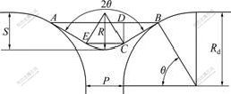
Fig.3 Diagram showing geometry structure of three-point bending
![]() (1)
(1)
3 Results and analysis
3.1 Effect of punch radius
With the foils of 40, 60, 80 and 100 ?m in thickness, respectively, the three-point bending tests were carried out. All of specimens were annealed at 450 ��. The punch radius was changed in tests, and the curves of bending force��punch displacement under different punch radii are shown in Fig.4.
The experimental results show that the bending force increases with the increasing of punch displacement. During the increase of bending force, inflection points appear. The punch displacement at the inflection points becomes smaller when the thickness increases. With the same thickness, a smaller punch radius leads to a larger bending force.
In the process of foil bending, the inflection points are considered the yield points. Fig.5 shows the diagram of strain calculation. The engineering strain can be calculated by Eq.(2):
![]() (2)
(2)
where �� is the bending angle; and R is the punch radius. With the increase of thickness, the engineering strain becomes larger, which leads to the reduction of punch displacement at inflection point. For the same reason, the increase of punch radius results in a larger engineering strain. The bending force increases with decreasing punch radius because of the work-hardening. With the decrease of thickness, the bending force becomes small. One reason is that the decrease of thickness causes the cross sectional area decreasing. Another reason is the free surface effect. For the existence of free surface layer, as shown in Fig.6, the flow stress decreases with the decrease of thickness[15].
3.2 Effect of grain size
The punch radius of 1 mm was selected. The foil
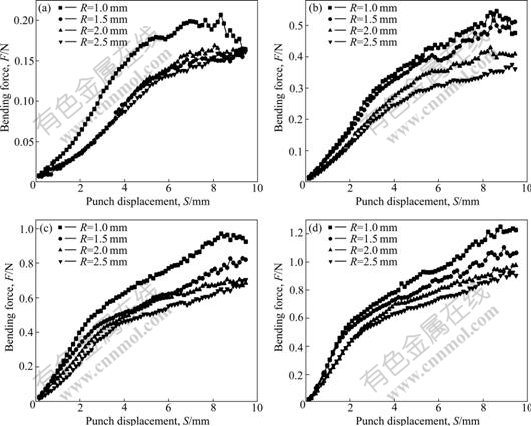
Fig.4 Curves of bending force��punch displacement under different punch radius: (a) 40 ?m in foil thickness; (b) 60 ?m in foil thickness; (c) 80 ?m in foil thickness; (d) 100 ?m in foil thickness
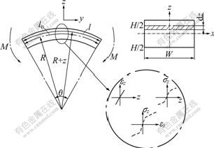
Fig.5 Diagram of strain calculation
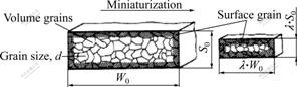
Fig.6 Relation of surface grains with volume grains
thicknesses were 60, 80 and 100 ?m, respectively. In order to investigate the effect of grain size, the annealing process was carried out at 350, 450, 550 and 650 ��, and the obtained grain size are listed in Table 1. The bending test results are shown in Fig.7. The results of tests show that bending force decreases with the increase of grain size. At the same time, both punch displacement and bending force become small at inflection points.
Table 1 Grain size of annealed brass foil
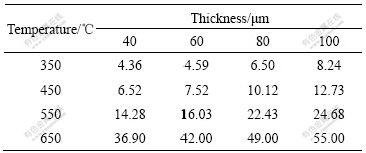
The decrease of bending force with increasing grain size can be explained by the empirical Hall-Petch equation. A larger grain leads to a smaller yield stress, which is one reason of decrease of bending force. From the viewpoint of free surface layer model, the volume ratio of free surface grains to volume grains increases with the increase of grain size when the thickness of foil keeps constant, so the yield stress becomes small. This is another reason of decrease of bending force.
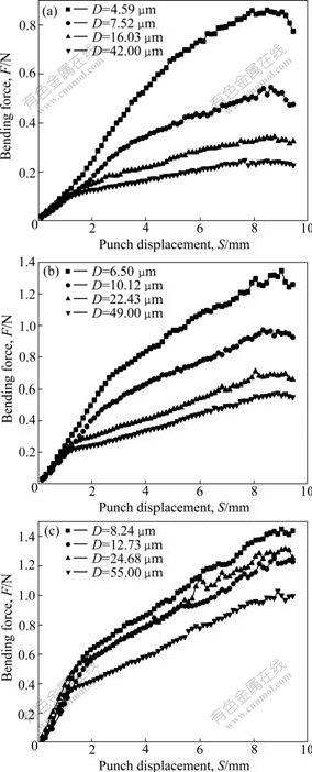
Fig.7 Curves of bending force��punch displacement under different grain sizes: (a) 60 ?m in foil thickness; (b) 80 ?m in foil thickness; (c) 100 ?m in foil thickness
4 Conclusions
1) The bending force increases with increasing the punch displacement. With the same foil thickness, a smaller punch radius leads to a larger bending force. This can be explained by the work-hardening phenomenon.
2) During the increase of bending force, inflection points appear. When the thickness increases, the punch displacement at the inflection points becomes small because of the free surface effect.
3) The bending force decreases with increasing the grain size, which can be analyzed by the empirical Hall-Petch equation. At the same time, both the punch displacement and bending force becomes small at inflection points.
References
[1] GEIGER M, KLEINER M, ECKSTEIN R. Microforming [J]. Annals of the CIRP, 2001, 50(2): 445-462.
[2] GEIGER M, MERKLEIN M, TOLAZZI M. Metal forming ensures innovation and future in Europe [C]// BARIANI P F. Proceeding of the 8th ICTP. Verona, 2005.
[3] YANG M, MANABE K, ITO K. Micro press forming and assembling of micro parts in a progressive die [J]. Journal of Mechanical Science and Technology, 2007, 21: 1452-1455.
[4] Mahabunphachai S, Muammer K. Investigation of size effects on material behavior of thin sheet metal using hydraulic bulge testing at micro/meso-scale [J]. International Journal of Machine Tools and Manufacture, 2008, 48: 1014-1029.
[5] VOLLERTSEN F, HU Z, SCHULZE N H, THEILER C. State of the art in micro forming and investigations into micro deep drawing [J]. Journal of Materials Processing Technology, 2004, 151: 70-79.
[6] Engel U, Eckstein R. Materials microforming��From basic research to its realization [J]. Journal of Materials Processing Technology, 2002, 125/126: 35-44.
[7] PICART P, MICHEL J F. Effects of size and texture on the constitutive behaviour for very small components in sheet metal forming [C]// Proceeding of the 6th ICTP. Nuremberg Germany, 1999: 895-900.
[8] DONG X, MA N. A study on size effects on process design of micro deep drawing [C]// BARIANI P F. Proceeding of the 8th ICTP. Verona, 2005.
[9] RAULEA L V, GOVAERT L E, BAAIJENS F P T. Grain and specimen size effects in processing metal sheets [C]// Proceeding of the 6th ICTP. Nuremberg Germany, 1999: 939-944.
[10] ECKSTEIN R, ENGEL U. Behavior of the grain structure in micro sheet metal working [C]// Metal Forming 2000. Krakow Poland, 2000: 453-459.
[11] MICHEL J F, PICART P. Size effects on the constitutive behaviour for brass in sheet metal forming [J]. Journal of Materials Processing Technology, 2003, 141: 439-446.
[12] YEH F H, LI C L, LU Y H. Study of thickness and grain size effects on material behavior in miro-forming [J]. Journal of Materials Processing Technology, 2008, 201: 237-241.
[13] LI L, ZHOU Q, ZHOU Y Y, CAO J G. Numerical study on the size effect in the ultra-thin sheet��s micro-bending forming process [J]. Mater Sci Eng A, 2008, 499(1/2): 32-35.
[14] JUSTINGER H, HIRT G. Estimation of grain size and grain size orientation influence in microforming processes by Taylor factor considerations [J]. Journal of Materials Processing Technology, 2009, 209: 2111-2121.
[15] ECKSTEIN R, GEIGER M, ENGEL U. Specific characteristics of micro sheet metal working [C]// Proceeding of SheMet. Braunschweig, Germany, 1999: 529-536.
(Edited by YANG Bing)
Foundation item: Project(2006AA04Z316) supported by the High-tech Research and Development Program of China; Project(2008RFQXG041) supported by the Foundation for Innovation Scholars of Harbin City, China; Project(50805035) supported by the National Natural Science Foundation for Young Scholars of China
Corresponding author: WANG Chun-ju; Tel: +86-451-86402775; E-mail: cjwang1978@hit.edu.cn
