

J. Cent. South Univ. (2020) 27: 2440-2454
DOI: https://doi.org/10.1007/s11771-020-4460-5

Effect of loading rates on crack propagating speed, fracture toughness and energy release rate using single-cleavage trapezoidal open specimen under impact loads
LANG Lin(����)1, ZHU Zhe-ming(������)2, WANG Han-bing(������)1,
HUANG Jian-wei(�ƽ�ΰ)1, WANG Meng(����)2, ZHANG Xian-shang(������)2
1. State Key Laboratory of Hydraulics and Mountain River Engineering, School of Architecture and Environment, Sichuan University, Chengdu 610065, China;
2. Key Laboratory of Deep Underground Science and Engineering of Ministry of Education,School of Architecture and Environment, Sichuan University, Chengdu 610065, China
 Central South University Press and Springer-Verlag GmbH Germany, part of Springer Nature 2020
Abstract:
The former studies indicate that loading rates significantly affect dynamic behavior of brittle materials, for instance, the dynamic compressive and tensile strength increase with loading rates. However, there still are many unknown or partially unknown aspects. For example, whether loading rates have effect on crack dynamic propagating behavior (propagation toughness, velocity and arrest, etc). To further explore the effect of loading rates on crack dynamic responses, a large-size single-cleavage trapezoidal open (SCTO) specimen was proposed, and impacting tests using the SCTO specimen under drop plate impact were conducted. Crack propagation gauges (CPGs) were employed in measuring impact loads, crack propagation time and velocities. In order to verify the testing result, the corresponding numerical model was established using explicit dynamic software AUTODYN, and the simulation result is basically consistent with the experimental results. The ABAQUS software was used to calculate the dynamic SIFs. The universal function was calculated by fractal method. The experimental-numerical method was employed in determining initiation toughness and propagation toughness. The results indicate that crack propagating velocities, dynamic fracture toughness and energy release rates increase with loading rates; crack delayed initiation time decreases with loading rates.
Key words:
Cite this article as:
LANG Lin, ZHU Zhe-ming, WANG Han-bing, HUANG Jian-wei, WANG Meng, ZHANG Xian-shang. Effect of loading rates on crack propagating speed, fracture toughness and energy release rate using single cleavage trapezoidal open specimen under impact loads [J]. Journal of Central South University, 2020, 27(8): 2440-2454.
DOI:https://dx.doi.org/https://doi.org/10.1007/s11771-020-4460-51 Introduction
Brittle materials, such as rock or concrete, often contain a large number of cracks or microcracks. Under external loading, these cracks may propagate violently, which will seriously affect the stability and service life of engineering structures. In addition, engineering structures are frequently subjected to dynamic loading, such as earthquakes, impacts and blasts. These three types of dynamic loadings have different loading rates, and the corresponding dynamic responses of brittle materials vary significantly with the loading rate.For cracked brittle materials, the properties of fracture toughness and crack response at initiation have been well investigated. However, the crack propagating behavior including propagation toughness, propagating speed and energy release rate under different loading rates has not been addressed yet.
In the dynamic tests of brittle materials, the mechanical response of brittle materials is related to the loading rates. Recently, the researches about loading rate effects are mainly carried out by compression tests [1-6], splitting tensile tests [7-12], and fracture tests [13-21]. The results show that the dynamic compressive strength of rock or concrete increases with loading rate, and the energy absorption increases linearly with strain rate [1-4]. The dynamic tensile strength of brittle materials is much higher than its static tensile strength, and the dynamic tensile strength increases with strain rate [7-11]. In the fracture tests, the researchers used different testing devices [9-14] and different specimen configurations [15-21] to study the crack propagating time, propagating speed, and initiation toughness. The results show that crack propagating velocity is not a constant value, and the initiation toughness increases with the increase of loading rate [17-28].
Recently, many new achievements have been made in testing the dynamic fracture properties of materials under split Hopkinson pressure bar (SPHB) impacts. Although the SHPB test system has been improved [29-32], due to the size of the SPHB pressure bar being still small [33, 34], only small-size specimens can be used to carry out impact tests, which could generate reflection wave at the free boundary of specimens. These reflected tensile waves may superimpose with compressive stress waves at the crack tip, and thus may seriously affect the test results of crack dynamic parameters. To avoid such effect, a large-sized single cleavage trapezoidal open (SCTO) compression specimen is proposed in this study, and a drop weight impact device, suitable for large-scale samples, is applied.
There are still some problems [20] in the impact testing, such as the instability of the impact device, the systematic error of the data acquisition system, and the error of the voltage conversion. Moreover, because of the limit of experimental conditions, some factors which may affect the test results largely cannot be considered in the tests. However, numerical simulation can reproduce the whole process of the experiment. It can verify the test results and predict the dynamic fracture performance which cannot be realized by the experimental technique. Consequently, an experimental-numerical method has been employed in the studying of rock or concrete dynamic fractures [35-39].
Although the previous studies [1-20] have shown that loading rate seriously affects the dynamic fracture performance of brittle materials. However, there still keep some unclear or partially unclear aspects, such as crack propagating speed, crack arrest characteristic and propagation toughness under different loading rates. Therefore, in this study, the impact dynamic experiments were carried out by using SCTO specimens under drop weight impacting. The effects of loading rate on crack dynamic propagating behavior and dynamic fracture parameters were investigated. The AUTODYN code has been applied in the study of rock or concrete dynamic response under impact loading [40, 41]. Therefore, it was employed in the simulation of crack propagation behavior.
2 Experimental study
Impact experiments were performed using SCTO specimens under drop plate impacting with different loading rates.
2.1 Specimen geometric dimension
In recent decades, researchers have proposed a variety of configuration specimens for investigating crack dynamic fracture behavior, such as the semi-circular bend specimen [15], the cracked chevron notched Brazilian disc specimen [16], the Brazilian Disc specimen [17], the holed-cracked flattened Brazilian disk specimen [18]. However, the size of these specimens was small, by which the crack dynamic response may be affected by the reflected tensile stress waves. Meanwhile, the crack propagation distance of small specimens is also short, which is not conducive to the study of crack propagating behavior. Therefore, several large configuration specimens, such as the single- cleavage semicircle compression specimen [19], the cracked tunnel specimen [20] and the large single cleavage semicircle compression specimen [21] were employed. However, because the specimens of these configurations have arc boundaries, it is not convenient to prefabricate, and thereby, a large- sized single cleavage trapezoidal open (SCTO) specimen is proposed in this study, and is depicted in Figure 1. The sample dimension is large enough for crack expansion and it is easy to prefabricate.
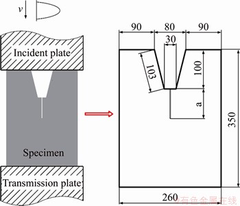
Figure 1 Loading diagram and geometric dimensions of SCTO specimen (Unit: mm)
The SCTO specimen measures 26 cm in width, 35 cm in height and 3 cm in thickness. There is a trapezoidal opening in the middle of the upper edge of the specimen. The prefabricated crack emanates from the midpoint of the trapezoid bottom and extends downward along the symmetrical axis of the specimen. The length of the prefabricated crack can be adjusted as needed. In this experimental study, the crack measures 5 cm in length and 0.1 cm in width.
2.2 Preparation of materials and specimens
In this experiment, cement fly ash mortar was selected to make the SCTO specimens. The cement mortar was produced by mixing water, cement, sand, fly ash and water reducer, and its mixing ratio was 300:490:1300:50:7.35. The common Portland cement P.O 42.5R, which is commonly used in infrastructure engineering, was employed. The local sand was selected with its gradation illustrated in Figure 2. The gradation curve of sand was located between the upper and lower values of zone 2 in the gradation area stipulated in the ��Sand for Construction�� (GB/T 14684-2011), so it belongs to medium sand and has a fineness modulus of 2.6. The fly ash was Grade II fly ash from Daishi Power Plant, and the water was tap water. Twelve cube samples, 12 Brazilian disc samples and 16 hexahedral samples were cast for testing the tensile strength, density, wave velocity and other parameters of cement mortar, with the mechanical parameters of cement mortar shown in Table 1.
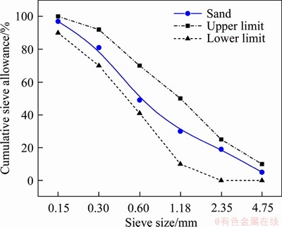
Figure 2 Fine aggregate screening curve
Thirty specimens with cement mortar material were poured. All samples and specimens were prepared in accordance with the following procedures. First, the mixed cement mortar was poured into the steel formwork, and then vibrated on the vibrating table. After the mortar final setting, the steel formwork was removed, the specimens were placed at room temperature for 24 h, and then transferred to a curing room with strictly controlled temperature and humidity. The curing room was maintained for 30-40 d until the test time.
2.3 Introduction of impact testing equipment
Drop weight impact device, which is suitable for large-sized specimens, was designed based on SPHB principle and was applied in this experiment, as shown in Figure 3. The material and the dimensions of the components of the device including the incident and transmission plates, as well as the drop plate, are listed in Table 2.
Table 1 Mechanical properties of cement mortar material

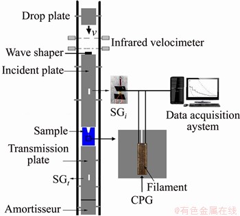
Figure 3 Impact testing equipment
During the experiment, the sample was placed between the transmission and incident plates, and two high-strength steel plates were used to clamp the specimen to prevent the specimen from buckling. Vaseline lubricant was applied on the contact surface between the plates and the specimen. In order to reduce high frequency oscillation, a brass waveform shaper was securely attached to the top end of the incident plate. Before experiments, the drop plate was raised to the required height, and then it fell down to impact the incident plate.
2.4 Measurement of dynamic loads
Two strain gauges (SGs) were pasted in the midpoint of the incident and the transmission plates, respectively, as depicted in Figure 3. In the tests, the voltage signals from the two strain gauges were collected by the oscilloscope and recorded by the data acquisition system. The typical curve of voltage signal history for the cement mortar material under impact speed 4.36 m/s is depicted in Figure 4(a). The strain is calculated after being denoised by the ORIGIN software [42]. The strain can be further converted to dynamic loads ��top(t) and ��bot(t) at the top and bottom of the sample, and they are expressed:

 (1)
(1)
where i, r and t are the subscripts representing incident, reflection and transmission, respectively; E is elastic modulus; �� is normal strain converted from the voltage signals; A is the cross-sectional area of the sample; AT is the cross-sectional area of the upper trapezoidal opening of the sample.
The oblique straight line of the ��top(t) history curve is defined as the loading rate, and it can be obtained by using the ORIGIN code to compute the derivative [38, 43]. For the mortar specimen, the dynamic stress history curve measured by using strain gauge under impact velocity 4.36 m/s is depicted in Figure 4(b). And the loading rate for the SCTO specimen is 312.79 GPa/s.
Table 2 Mechanical parameters of various components of impact testing system
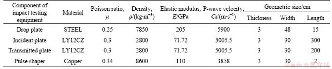
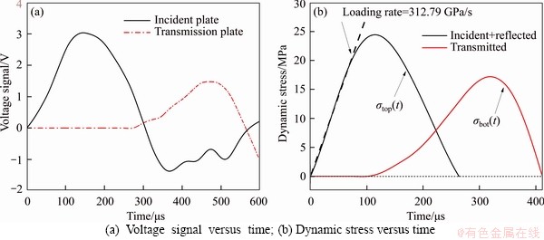
Figure 4 Loading curves for a SCTO specimen under impact speed 4.36 m/s:
3 Numerical simulation by using finite difference method
3.1 Numerical models
To confirm the applicability of the SCTO specimen and to forecast the experimental results, numerical studies were carried out before the tests. The software AUTODYN has been used extensively to the study of dynamic fractures [14, 19-21, 23, 39-41], and therefore, it was employed in this study.
According to the impact device and the specimen configuration, numerical models including all the components of the impacting system were established, with the mesh shown in Figure 5. Quadrilateral elements were used for meshing the impacting device and the SCTO specimen. The element number of the SCTO specimen is 157800. The minimum sizes of elements are 1.0 mm��1.0 mm. In order to transfer the stress wave, there is a gap of 0.08 mm between the specimen and the plate of the impact device, as shown in Figure 5.
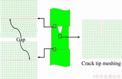
Figure 5 Meshing of SCTO specimen and impact device
The grid dependency survey was conducted using grid sizes of 0.5, 1.0, 1.5 2.0 and 3.0 mm, and the inspection results showed that as the grid size was less than 2.0 mm, and there was no significant change in the calculation results, which means that the grid size 2.0 mm is small enough to meet the accuracy requirements of numerical simulation.
For all the materials in this impacting system, either the pressure or deformation in the test is small, so the linear equation of state is employed in this simulation.
 (2)
(2)
where P is pressure; k is bulk modulus; �� is current density and ��0 is initial density.
There is no failure for all the components in this impacting system, so failure criterion is not necessary to apply to them, but for mortar material, the maximum tensile stress failure model with tensile fracture softening damage criteria is applied.
When the major principal stress ��1 exceeds the dynamic tensile strength ��t of the material, the element will fail, and then the tensile fracture softening damage criterion is used to describe the failure process of materials. The criterion can be expressed as:
 (3)
(3)
where D is damage factor and ��max is the bearing maximum principle stress.
3.2 Simulation results and analysis
For one SCTO specimen under the loading speed 4.5 m/s, the numerical and test results of crack propagating paths and the contour plots of stress ��1 are presented in Figure 6. The numerical results are basically consistent with the testing results. However, slight difference can be observed, which could be induced by the mortar heterogeneity. The crack fracture characteristics of the SCTO specimen is a typical pure mode I fracturing, which was induced by tensile stress.
A group of Gauss points was selected on the crack propagating path with 1.0 mm interval as depicted in Figure 6. According to the Gaussian point spacing and the fracturing time of each element, the crack propagating velocity can be obtained. The crack propagating velocities at impact speeds of 2.5, 4.5, 6.5 and 8.5 m/s are plotted in Figure 7. It shows that the crack propagating speed is not a constant. Generally, the crack velocity is lower at the initial stage. This is because the crack cannot initiate immediately under the compressive wave. During the propagating, crack arrest phenomenon occurred, and for all the specimens, this phenomenon occurred more than once. It is worth noting that many arrest phenomena happened in the place beyond the coverage of the 44 mm CPG, and thus most of crack arrest phenomena were not monitored by the CPGs.
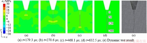
Figure 6 Crack extending paths and contour plots of stress ��1 under impact speed 4.5 m/s:
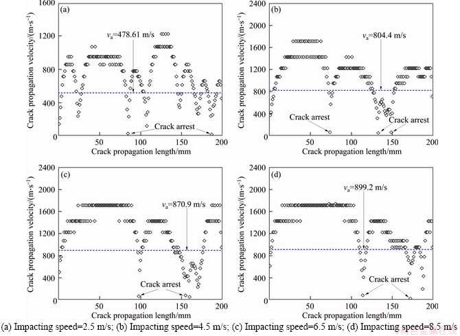
Figure 7 Simulation results of crack propagation velocities versus crack lengths under different impact velocities:
Figure 8(a) shows the curve of average crack propagating velocity versus loading rates. It shows that the propagating velocity increases as the loading rate increases, and as it exceeds 370 GPa/s, the average crack propagating speed tends to be a constant which is about 40% of Rayleigh wave speed.
Figure 8(b) shows the curve of the longest arrest period versus loading rate. It shows the longest arrest period decreases with loading rate. This is because the greater the impact speed is, the greater the impact energy produced is, and the shorter the crack arrest periods are.
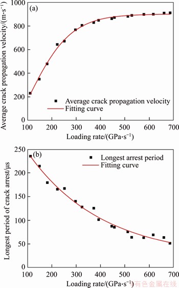
Figure 8 Simulation results of curves of average crack propagating speed (a) and longest arrest period (b) versus loading rates
The concept of delayed initiation time refers the difference between crack initiation time and the time of stress wave reaching crack tip. Figure 9 shows the delayed initiation time and the maximum compressive stress at crack tip versus loading rate. One can find that the delayed initiation time decreases with loading rate. Meanwhile, the maximum compressive stress at crack tip increases with loading rate, and when it exceeds 350 GPa/s, the delayed initiation time tends to be a constant. The maximum compressive stress at crack tip increases linearly with loading rate. The smaller the maximum compressive stress is, the longer the crack delayed initiation time is.
3.3 Particle velocity at moment of crack initiation, arrest and re-initiation
The SCTO specimen under impact speed 4.5 m/s is selected as an example to illustrate how the crack initiates, arrests and re-initiates. At the moment of initiation and arrest and re-initiation, the vectors of particle velocity are illustrated in Figure 10. At 179.3 ��s, just before the reflected wave head reached the front of the crack, the crack was initiated as depicted in Figure 10(a). The corresponding particles were moving down, as shown in Figure 11(a).
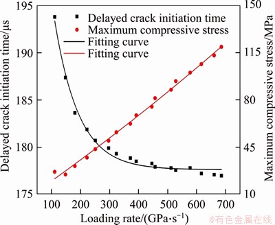
Figure 9 Variation curves of delayed initiation time and maximum compressive stress at crack tip under different loading rates
At 270.6 ��s, the crack has propagated 73.5 mm. The 2nd reflected wave was moving down from the top, as shown in Figure 10(b), but the 1st reflected wave was moving up which is larger (20.8 MPa) than the 2nd reflected wave (14.3 MPa) in amplitude, so that the particles were moving up, as illustrated in Figure 11(b). Therefore, the crack was arrested at this moment.
At 398.7 ��s, the positions of the 2nd, 3rd and 4th reflected waves are shown in Figure 10(c), and the particle velocity is shown in Figure 11(c). It can be seen that at this moment, the particle velocity was inclined and the horizontal component of the stress was tensile, which caused the crack re-initiation.
4 Experimental results and discussion
4.1 Crack propagating time and velocity
The CPGs consist of a number of filaments with equal spacing and glass cloth substrate, as illustrated in Figure 3. The CPG size used in the tests is 4.4 cm��1.8 cm, and the spacing between two adjacent filaments is 0.22 cm.
Before testing, the surface of the specimen was polished smoothly, and the CPGs was pasted along the crack propagation path with high-strength glue, as shown in Figure 3. The first filament of the CPG just coincided with the pre-crack tip to monitor crack initiation time. The CPG filaments will break when the crack moving through the CPG, and the voltage signal recorded by the ultra-dynamic strain gauge will correspondingly exhibit jumping changes. The CPG voltage signals recorded, and the extremum of the voltage derivation are the filament breaking time. For SCTO specimen 4, the voltage signal and its derivative versus time under impact speed 4.36 m/s are plotted in Figure 12(a). The crack initiation time obtained is 199.5 ��s. For the SCTO specimen 4, the crack propagating velocity and crack propagating length as a function of time are shown in Figure 12(b). The crack propagating velocity is not a constant value along the crack path, but fluctuates over time. The crack initiation velocity is 916.67 m/s, and the average crack propagation velocity va is 715.91m/s.
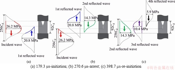
Figure 10 Wave positions at moment initiation, arrest and re-initiation under loading speed 4.5 m/s (Cd represents longitudinal wave speed of mortar):

Figure 11 Particle velocity at moment of crack initiation, arrest and re-initiation:
4.2 Effect of loading rate on crack propagating speed and delayed initiation time
Figure 13(a) shows the curve of the average crack propagating velocity versus loading rate. From 170 to 320 GP/s, the crack propagating velocity increases with loading rate. However, when it is greater than 320 GP/s, the crack propagating velocity increases slightly. This indicates that for the cement mortar, when the loading rate increases to a certain value, the crack propagating velocity increases slightly.
The difference between the time of stress wave reaching crack tip and the time of crack initiation is defined as delayed initiation time. Figure 13(b) shows the crack delayed initiation time versus loading rate. The crack delayed initiation time decreases with loading rate, which indicates that the larger the loading rate is, the easier the crack initiation is. When the loading rate is greater than 320 GP/s, the delayed initiation time tends to be a constant value.

Figure 12 Calculation of CPG breaking time and crack propagating velocity from SCTO specimen 4:
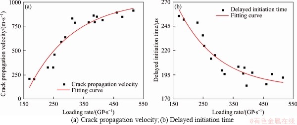
Figure 13 Crack propagating velocity and delayed initiation time versus loading rate:
5 Calculation of initiation toughness and propagation toughness
5.1 Establishment of numerical model
To calculate dynamic stress intensity factor (DSIF) of a running crack, finite element models were established using the ABAQUS program. A total of 10350 elements were used in the model. The models were meshed by using eight-node quadrilateral CPS8 elements. To eliminate crack tip singularity, crack tip regions were meshed using singular six-node triangle CPS6 elements, as depicted in Figure 14.
Dynamic loads ��top(t) and ��bot(t) obtained by Eq. (1) were loaded to the top and bottom of the SCTO specimen, respectively. The SIF KI(t) of the SCTO specimen was calculated by Eq. (4) [14] based on the displacements��uN(t) and uM(t) at points N and M in the horizontal direction shown in Figure 14, respectively.
 (4)
(4)
where E is elastic modulus; �� is Poisson ratio;rON=4rOM as shown in Figure 14.
5.2 Modification of universal function and calculation of DSIFs
To explore crack propagating path characteristics, fracture surfaces were pictured. The results show that the crack path is curved and the crack fracture surface is not smooth and flat. In this study, fractal dimensions of crack paths were calculated by the box-counting method [44, 45].
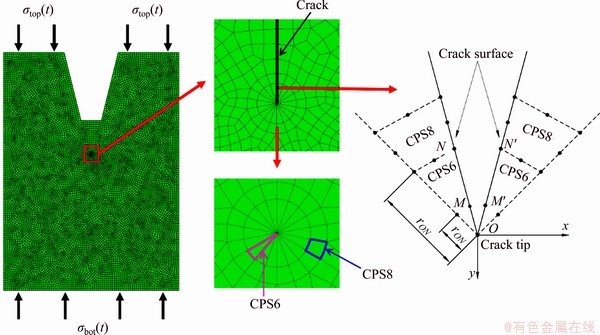
Figure 14 Schematic diagram of meshing of SCTO specimens by ABAQUS program
The fractal length L�� of crack path is greater than its straight distance L0, as shown in Figure 15(a). The ratio �� of crack fractal velocity V to crack straight velocity v can be obtained by the following formula:
 (5)
(5)
where �� is the edge dimension of the basic square lattice; d is average grain size (the average value is 0.18 mm); D is the fractal dimension.
Changing the scale of the basic square lattice d will result in different values of N(��), and the fractal dimension D can be expressed as
 (6)
(6)
Based on the above method, the fractal dimension of crack path can be calculated.Figure 15(b) gives the relationship between lgN(��) and lg�� for SCTO specimen 4. D is the slope of the fitting line, and D=1.038 in Figure 15(b).
According to ROSE [46] and BHAT et al [47], the DSIF for a moving crack can be written as
 (7)
(7)
where is SIF of stationary crack; k(V) is universal function.
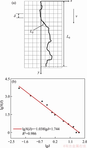
Figure 15 Fractal dimension method of crack propagation and relationship between log of number of occupied boxes N(��) plotted and log of box size ��
Based on Freund��s dynamic fracture mechanics theory [48], k(V) can be expressed as:
 (8)
(8)
where Cd is dilatation wave speed and CR is Rayleigh wave speed.
Substituting Eq. (5) into Eq. (8), k(V) can give:
 (9)
(9)
5.3 Effect of loading rate on fracture toughness
In this impact tests, totally 17 specimens were successfully tested and the data were measured. According to the method introduced in Section 4.1, the fracture time of all the specimens was obtained, and the crack propagating velocity was calculated. The experimental-numerical method has been applied by many researchers in determining fracture toughness [19-21, 34, 35], and in this study, it was employed. Next, specimen 4 was selected as an example to demonstrate how to determine crack initiation and propagation toughness.
Based on SCTO specimen configuration in Figure 1 and the dynamic loads calculated from Eq. (1), a numerical model was established using ABAQUS software as shown in Figure 14. The result of DSIFs as a function of time is depicted in Figure 16 for specimen 4 with loading rate 312.79 GPa/s. Figure 16(a) shows that the maximum of DSIF is 5.021 MPa��m1/2, but the initiation time of this crack is t1=199.5 ��s, by which the critical DSIF 3.369 MPa��m1/2 can be determined, as shown in Figure 16(a). Because V=0, k(V)=1, the initiation toughness MPa��m1/2.
For moving cracks, we choose the crack moving to the 11th filament of the CPG pasted on specimen 4 as an example. The crack length at the 11th filament is 72 mm, and the breaking time from Figure 12(a) is t11=233.56 ��s. Based on the spacing 22 mm and the time difference, the average crack propagation velocity is 687.5 m/s. From Eq. (9), one can have k(V)=0.7574. From Eq. (7), the critical DSIFs  were calculated as plotted in Figure 16(b). The critical DSIF
 MPa��m1/2 corresponding to the breaking time 233.56 s. For the rest wires of the CPG, using the similar method, the critical DSIFs were obtained.
For specimen 4, the average critical DSIF of the 21 wires of the CPG is calculated and the result is 2.652 MPa��m1/2, which may be regarded as the propagation toughness of cement mortar measured by specimen 4.
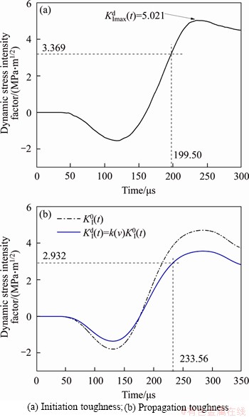
Figure 16 Dynamic initiation and propagation toughness measured by SCTO specimen 4:
Figure 17(a) shows the two curves of crack initiation and propagation toughness, obtained in this experiment. One can find either the initiation toughness or propagation toughness increases with loading rates. However, the increase rate of the propagation toughness is smaller than that of the initiation toughness, and the initiation toughness is generally greater than the propagation toughness under a same loading rate.
5.4 Effect of loading rate on energy release rate
Energy release rate is energy dissipation rate of each unit at crack tip, and it may be expressed as [49, 50]:
 (10)
(10)
where and
and are fracture energies of stationary crack in mode I and mode II, respectively, and
  represents energy release rate. Because of mode I fracturing, is equal to zero in this study. Therefore, one can rewrite Eq. (10) as:
 (11)
(11)
where �� is dynamic Poisson ratio; V is crack fractal speed; A(V) is split speed function, and when V =0, A(V)=1.
For all the specimens, the energy release rates GD(t) were calculated using Eq. (11). The curves of GD(t) versus loading rate for cracks at initiation and propagation are depicted in Figure 17(b). It shows that the release rates at both initiation and propagation increase with loading rate, but for the crack at propagation, the increase rate is smaller than that at initiation. In addition, the release rate at initiation is larger than that at propagation, and the average ratio of the release rate at initiation is 1.4 times that at propagation. This indicates that more energy is needed at the crack initiation, and in propagating process, the energy required is comparatively small. This may be induced by the inertia effect.
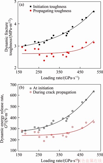
Figure 17 Relation of fracture toughness versus loading rates (a) and energy release rate versus loading rates (b)
6 Conclusions
To investigate the effect of loading rate on crack propagating behavior, a large size single cleavage trapezoidal open (SCTO) specimen was employed, and impacting tests were carried out using the SCTO specimen under drop weight impacting. The AUTODYN and ABAQUS software were employed in the simulations. The fracture parameters of crack propagating path, velocity, delayed initiation time and DSIFs were obtained. The following conclusions can be obtained:
1) The SCTO specimen proposed in this paper is suitable for studying the effect of loading rate on crack propagating characteristics. The SCTO specimen has the simple geometry and is easily manufacturing, especially for cement mortar or concrete materials.
2) Crack propagation velocities increase with loading rates, and crack delayed initiation time decreases with loading rates.
3) Reflected compressive stress waves caused by transmission and incident plates play a key role in crack arrest; When a crack is arrested, the particle velocity vector is in the opposite direction with the propagating crack.
4) Initiation fracture toughness is greater than propagation toughness, and because of the inertia effect, the energy release rate at initiation is larger than that at propagation.
References
[1] HUANG B, LIU J. The effect of loading rate on the behavior of samples composed of coal and rock [J]. International Journal of Rock Mechanics and Mining Sciences, 2013, 61: 23-30. DOI: 10.1016/j.ijrmms.2013.02.002.
[2] LI X B, LOK T S, ZHAO J. Dynamic characteristics of granite subjected to intermediate loading rate [J]. Rock Mechanics and Rock Engineering, 2004, 38: 21-39. DOI: 10.1007/s00603-004-0030-7.
[3] KIM D J, SIRIJAROONCHAI K, EL-TAWIL S. NAAMAN A E. Numerical simulation of the split Hopkinson pressure bar test technique for concrete under compression [J]. International Journal of Impact Engineering, 2010, 37: 141-149. DOI: 10.1016/j.ijimpeng.2009.06.012.
[4] CAO A, JING G, DING Y, LIU S. Mining-induced static and dynamic loading rate effect on rock damage and acoustic emission characteristic under uniaxial compression [J]. Safety Science, 2019, 116: 86-96. DOI: 10.1016/j.ssci.2019. 03.003.
[5] KOMURLU E. Loading rate conditions and specimen size effect on strength and deformability of rock materials under uniaxial compression [J]. International Journal of Geo-Engineering, 2018, 9(1): 1-11. DOI: 10.1186/s40703- 018-0085-z.
[6] ELMER VII W, TACIROGLU E, MCMICHAEL L. Dynamic strength increase of plain concrete from high strain rate plasticity with shear dilation [J]. International Journal of Impact Engineering, 2012, 45: 1-15. DOI: 10.1016/ j.ijimpeng.2012.01.003.
[7] HEIDARI-RARANI M, ALIHA M R M, SHOKRIEH M, AYATOLLAHI M R. Mechanical durability of an optimized polymer concrete under various thermal cyclic loadings-An experimental study [J]. Construction and Building Materials, 2014, 64: 308-315. DOI: 10.1016/j.conbuildmat.2014.04. 031.
[8] KIM E, CHANGANI H. Effect of water saturation and loading rate on the mechanical properties of red and buff sandstones [J]. International Journal of Rock Mechanics and Mining Sciences, 2016, 88: 23-28. DOI: 10.1016/j.ijrmms. 2016.07.005.
[9] YIN Zhi-qiang, CHENWen-su, HAO Hong, CHANG Ju-cai, ZHAO Guang-ming, CHEN Zhi-yu, PENG Kang.Dynamic compressive test of gas-containing coal using a modified split Hopkinson pressure bar system [J]. Rock Mechanics and Rock Engineering, 2020, 53: 815-829. DOI: 10.1007/ s00603-019-01955-w.
[10] ZHU Z M, XU W T, FENG R Q. A new method for measuring mode-I dynamic fracture toughness of rock under blasting loads [J]. Experimental Techniques, 2016, 40(3): 889-905. DOI: 10.1007/s40799-016-0093-x.
[11] HUANG Hua, YUAN Yu-jie, ZHANG Wei, GAO Zi-chen. Bond behavior between lightweight aggregate concrete and normal weight concrete based on splitting-tensile test [J]. Construction and Building Materials, 2019, 209: 306-314. DOI: 10.1016/j.conbuildmat.2019.03.125.
[12] GUL A J, FATEHI M S, YASMEEN G, SHARIFAH M M, NORAM I R.Uniaxial compression and tensile splitting tests on adobe with embedded steel wire reinforcement [J]. Construction and Building Materials, 2018, 176: 383-393. DOI: 10.1016/j.conbuildmat.2018.05.006.
[13] WANG Q Z, YANG J R, ZHANG C G, ZHOU Y, LI L, ZHU Z M, WU L Z. Sequential determination of dynamic initiation and propagation toughness of rock using an experimental-numerical- analytical method [J]. Engineering Fracture Mechanics, 2015, 141: 78-94. DOI: 10.1016/ j.engfracmech.2015.04.025.
[14] WANG X M, ZHU Z M, WANG M, YING P, ZHOU L, DONG Y Q. Study of rock dynamic fracture toughness by using VB-SCSC specimens under medium-low speed impacts [J]. Engineering Fracture Mechanics, 2017, 181: 52-64. DOI: 10.1016/j.engfracmech.2017.06.024.
[15] KURUPPU M D, OBARA Y, AYATOLLAHI M R, CHONG K P, FUNATSU T. ISRM-suggested method for determining the mode I static fracture toughness using semi-circular bend specimen [J]. Rock Mechanics and Rock Engineering, 2014, 47(1): 267-274. DOI: 10.1007/s00603-013-0422-7.
[16] ALIHA M R M, AYATOLLAHI M R. Rock fracture toughness study using cracked chevron notched Brazilian disc specimen under pure modes I and II loading-A statistical approach [J]. Theoretical and Applied Fracture Mechanics, 2014, 69(2): 17-25. DOI: 10.1016/j.tafmec.2013.11.008.
[17] GUO H, AZIZ N I, SCHMIDT L C. Rock fracture-toughness determination by the Brazilian test [J]. Engineering Geology, 1993, 33(3): 177-188. DOI: 10.1016/0013-7952(93)90056-I.
[18] AKBARDOOST J, GHADIRIAN H R, SANGSEFIDI M. Calculation of the crack tip parameters in the holed-cracked flattened Brazilian disk (HCFBD) specimens under wide range of mixed mode I/II loading [J]. Fatigue & Fracture of Engineering Materials & Structures, 2017, 40: 1416-1427. DOI: 10.1111/ffe.12585.
[19] WANG M, ZHU Z M, DONG Y Q, ZHOU L. Study of mixed-mode I/II fractures using single cleavage semicircle compression specimens under impacting loads [J]. Engineering Fracture Mechanics, 2017, 177: 33-44, DOI: 10.1016/j.engfracmech.2017.03.042.
[20] ZHOU L, ZHU Z M, QIU H, ZHANG X S, LANG L. Study of the effect of loading rates on crack propagation velocity and rock fracture toughness using cracked tunnel specimens [J]. International Journal of Rock Mechanics and Mining Sciences, 2018, 112: 25-34. DOI: 10.1016/j.ijrmms.2018. 10.01.
[21] YING P, ZHU Z M, WANG F, WANG M, NIU C, ZHOU L. The characteristics of dynamic fracture toughness and energy release rate of rock under impact [J]. Measurement, 2019, 147: 106884. DOI: 10.1016/j.measurement.2019.106884.
[22] TANG S B. The effect of T-stress on the fracture of brittle rock under compression [J]. International Journal of Rock Mechanics & Mining Sciences, 2015, 79: 86-98. DOI: 10.1016/j.ijrmms.2015.06.009.
[23] LANG L, ZHU Z, ZHANG X, QIU H, ZHOU C L. Investigation of crack dynamic parameters and crack arresting technique in concrete under impacts [J]. Construction and Building Materials, 2019, 199: 321-334. DOI: 10.1016/j.conbuildmat.2018.12.029.
[24] TANG S B. Stress intensity factors for a Brazilian disc with a central crack subjected to compression [J]. International Journal of Rock Mechanics & Mining Sciences, 2017, 93: 38-45. DOI: 10.1016/j.ijrmms.2017.01.003.
[25] TANG S B, BAO C Y, LIU H Y. Brittle fracture of rock under combined tensile and compressive loading conditions [J]. Canadian Geotechnical Journal, 2017, 54(1): 88-101. DOI: 10.1139/cgj-2016-0214.
[26] ZHANG Z X, KOU S Q, JIANG L G, LINDQVIST P A. Effects of loading rate on rock fracture: Fracture characteristics and energy partitioning [J]. International Journal of Rock Mechanics & Mining Sciences, 2000, 37: 745-762. DOI: 10.1016/S1365-1609(00)00008-3.
[27] ZHAO Y, GONG S, HAO X, PENG Y, JIANG Y. Effects of loading rate and bedding on the dynamic fracture toughness of coal: Laboratory experiments [J]. Engineering Fracture Mechanics, 2017, 178: 375-391. DOI: 10.1016/ j.engfracmech.2017.03.011.
[28] SATYANARAYANA A, GATTU M. Effect of displacement loading rates on mode-I fracture toughness of fiber glass-epoxy composite laminates [J]. Engineering Fracture Mechanics, 2019, 218: 1-19. DOI: 10.1016/j.engfracmech. 2019.106535.
[29] FREW D J, FORRESTAL M J, CHEN W. A split Hopkinson pressure bar technique to determine compressive stress-strain data for rock materials [J]. Experimental Mechanics, 2001, 41(1): 40-46. DOI: 10.1007/BF02323102.
[30] NASSERI M H B, MOHANTY B. Fracture toughness anisotropy in granitic rocks [J]. International Journal of Rock Mechanics & Mining Sciences, 2008, 45(2): 167-193. DOI: 10.1016/j.ijrmms.2007.04.005.
[31] ZHOU Z, LI X, LIU A, ZOU Y. Stress uniformity of split Hopkinson pressure bar under half-sine wave loads [J]. International Journal of Rock Mechanics & Mining Sciences, 2011, 48(4): 697-701. DOI: 10.1016/j.ijrmms.2010.09.006.
[32] ZHANG Q B, ZHAO J. Effect of loading rate on fracture toughness and failure micromechanisms in marble [J]. Engineering Fracture Mechanics, 2013, 102(2): 288-309. DOI: 10.1016/j.engfracmech.2013.02.009.
[33] IMANI M, NEJATI H R, GOSHTASBI K. Dynamic response and failure mechanism of Brazilian disk specimens at high strain rate [J]. Soil Dynamics and Earthquake Engineering, 2017, 100: 261-269. DOI: 10.1016/j.soildyn. 2017.06.007.
[34] YANG R, CHEN J, YANG L, FANG S, LIU J. An experimental study of high strain-rate properties of clay under high consolidation stress [J]. Soil Dynamics and Earthquake Engineering, 2017, 92: 46-51. DOI: 10.1016/ j.soildyn.2016.09. 036.
[35] WANG Q Z, FENG F, NI M, GOU X P. Measurement of mode I and mode II rock dynamic fracture toughness with cracked straight through flattened Brazilian disc impacted by split Hopkinson pressure bar [J]. Engineering Fracture Mechanics, 2011, 78(12): 2455-2469. DOI: 10.1016/ j.engfracmech.2011.06.004.
[36] HAERI H, SHAHRIAR K, MARJI M F, MOAREFVAND P. Experimental and numerical study of crack propagation and coalescence in pre-cracked rock-like disks [J]. International Journal of Rock Mechanics & Mining Sciences, 2013, 67(4): 20-28. DOI: 10.1016/j.ijrmms.2014.01.008.
[37] FAYE A, PARAMESWARAN V, BASU S. Dynamic fracture initiation toughness of PMMA: A critical evaluation [J]. Mechanics of Materials, 2016, 94: 156-169. DOI: 10.1016/ j.mechmat.2015.12.002.
[38] HAERI H, SARFARAZI V, ZHU Z. Effect of normal load on the crack propagation from preexisting joints using particle flow code (PFC) [J]. Computers and Concrete, 2017, 19(1): 99-110. DOI: 10.12989/cac.2017.19.1.099.
[39] LANG L, ZHU Z M, DENG S, WANG L, NIU C Y, XIAO D J. Study on the arresting mechanism of two arrest-holes on moving crack in brittle material under impacts [J]. Engineering Fracture Mechanics, 2020, 229(39): 1-14. DOI: 10.1016/j.engfracmech.2020. 10693.
[40] ZHU Z. Numerical prediction of crater blasting and bench blasting [J]. International Journal of Rock Mechanics & Mining Sciences, 2009, 46(6): 1088-1096. DOI: 10.1016/j.ijrmms.2009.05.009.
[41] ZHU Z, WANG C, KANG J, LI Y, WANG M. Study on the mechanism of zonal disintegration around an excavation [J]. International Journal of Rock Mechanics & Mining Sciences, 2014, 67(4): 88-95. DOI: 10.1016/j.ijrmms.2013.12.017.
[42] YE W P. Origin 9.1 science and technology drawing and data analysis [M]. Beijing: Mechanical Industry Press, 2015: 299-319.
[43] ZHOU Y X, XIA K, LI X B, LI H B, MA G W, ZHAO J, ZHOU Z L, DAI F. Suggested methods for determining the dynamic strength parameters and mode-I fracture toughness of rock materials [J]. International Journal of Rock Mechanics & Mining Sciences, 2012, 49(1): 105-112. DOI: 10.1016/j.ijrmms.2011.10.004.
[44] XIE H P, SANDERSON D J. Fractal kinematics of crack propagation in geomaterials [J]. Engineering Fracture Mechanics, 1995, 50(4): 529-536. DOI: 10.1016/0013- 7944(94)00203-T.
[45] XIE H P, SANDERSON D J. Fractal effects of crack propagation on dynamic stress intensity factors and crack velocities [J]. International Journal of Fracture, 1986, 74: 29-42. DOI: 10.1007/BF00018573.
[46] ROSE L R F. On the initial motion of a Griffith crack [J]. International Journal of Fracture, 1976, 12(6): 829-841. DOI: 10.1007/bf00034622.
[47] BHAT H S, ROSAKIS A J, SAMMIS C G. A micromechanics based constitutive model for brittle failure at high strain rates [J]. Journal of Applied Mechanics, 2012, 79(3): 031016. DOI: 10.1115/1.4005897.
[48] FREUND L B. Dynamic fracture mechanics [M]. Cambridge University Press, 1990.
[49] RAVI-CHANDAR K. Dynamic fracture [M]. Elsevier, 2004.
[50] FREUND L B, HUTCHINSON J W. Dynamic fracture mechanics [J]. Journal of Applied Mechanics, 1992, 59(1): 245. DOI: 10.1115/1.2899458.
(Edited by YANG Hua)
���ĵ���
����غ��¼����ʶ�������չ�ٶȡ������ͶȺ������ͷ��ʵ�Ӱ��
ժҪ��ͨ���������ʻ�����Ӱ����Բ��ϵĿ�ѹǿ�Ⱥ�����ǿ�ȵ���ѧ��Ϊ�����Ƕ�������̬��ѧ���ܵ�Ӱ����Ȼ��������δ֪��δ֪����������磬�������Ƿ��Ӱ�����ƵĶ�̬��չ��Ϊ(��չ�Ͷȣ������ٶȺ�����ֹ�ѵ�)��Ϊ�˽�һ��̽�ּ����ʶ����ƶ�̬��Ӧ��Ӱ�죬������ο��ڵIJ�����ƹ��������������䴸���װ���¶Ը����������˳�����顣����������չ�Ʋ�������غɡ�������չʱ��������ٶȡ�Ϊ����֤���Խ����������ʽ��������AUTODYN��������Ӧ����ֵģ�ͣ���ֵ��������ʵ��������һ�¡���������Ԫ����ABAQUS���㶯̬Ӧ��ǿ�����ӣ����������ʺ�������������������ʵ��-��ֵ����ȷ��������ʼ�ͶȺ�������չ�Ͷȡ����������������չ�ٶȡ���̬�����ͶȺ������ͷ��ʾ����ż����ʵ����Ӷ����ӣ����Ƶ��ӳ�����ʱ�����ż����ʵ����Ӷ����̡�
�ؼ��ʣ������ٶȣ���̬�����Ͷȣ������ٶȣ������ʣ����ο��ڵĵ����ƹ���(SCTO)����
Foundation item: Projects(11672194, U19A2098) supported by the National Natural Science Foundation of China; Project(2018SCU12047) supported by Fundamental Research Funds for the Central Universities, China; Project(2018JZ0036) supported by the Project of Science and Technology of Sichuan Province, China
Received date: 2020-02-10; Accepted date: 2020-06-03
Corresponding author: ZHU Zhe-ming, PhD, Professor; Tel: +86-18980630656; E-mail: zhemingzhu@hotmail.com; ORCID: https:// orcid.org/0000-0003-3061-0099
Abstract: The former studies indicate that loading rates significantly affect dynamic behavior of brittle materials, for instance, the dynamic compressive and tensile strength increase with loading rates. However, there still are many unknown or partially unknown aspects. For example, whether loading rates have effect on crack dynamic propagating behavior (propagation toughness, velocity and arrest, etc). To further explore the effect of loading rates on crack dynamic responses, a large-size single-cleavage trapezoidal open (SCTO) specimen was proposed, and impacting tests using the SCTO specimen under drop plate impact were conducted. Crack propagation gauges (CPGs) were employed in measuring impact loads, crack propagation time and velocities. In order to verify the testing result, the corresponding numerical model was established using explicit dynamic software AUTODYN, and the simulation result is basically consistent with the experimental results. The ABAQUS software was used to calculate the dynamic SIFs. The universal function was calculated by fractal method. The experimental-numerical method was employed in determining initiation toughness and propagation toughness. The results indicate that crack propagating velocities, dynamic fracture toughness and energy release rates increase with loading rates; crack delayed initiation time decreases with loading rates.
