

General issues of FEM in backward ball spinning of thin-walled tubular part with longitudinal inner ribs
JIANG Shu-yong(������), REN Zheng-yi(������), WU Bin(�� ��), WU Gui-xiang(�����)
Engineering Training Center, Harbin Engineering University, Harbin150001,China
Received 25 July 2006; accepted 15 June 2007
Abstract:
Backward ball spinning was applied for manufacturing thin-walled tubular parts with longitudinal inner ribs. Rigid-plastic finite element method(FEM) was used for simulating the backward ball spinning process in order to calculate the height of the inner ribs. With a view to guarantee a better simulation accuracy, it is essential to enhance and improve some general problems of FEM, such as generation of initial velocity field, choice of penalty factor, determination of boundary conditions, treatment of rigid region and description of convergence criteria. It is evident that whether the problems with respect to FEM are dealt with appropriately or not, they have a significant influence on the modeling accuracy and efficiency. By reasonable solving the general problems, rigid-plastic FEM can successfully simulate the height of the inner ribs and the calculated values are in good agreement with the measured values.
Key words:
ball spinning; tube spinning; power spinning; finite element method; longitudinal inner ribs;
1 Introduction
As a successive and local point-to-point plastic deformation process, ball spinning belongs to tube spinning using balls as deformation tool instead of rollers [1-2]. Ball spinning is characterized by its fairly small deformation zone as well as relatively low forming loads, compared with tube spinning using rollers. In addition, the balls are distributed so uniformly along the circumference of deformation zone that the circumferential flow of metal in the deformation zone is confined to make the mandrel keep good balance and stability, which contributes more greatly to enhance the dimensional accuracy of the spun part. The ball spinning process is able to manufacture the tubular part with better finish surface and larger ratio of length vs diameter as well[3-4].
The predominant advantages to the ball spinning process mentioned above make it possible to apply the ball spinning process to form the thin-walled tubular parts with longitudinal inner ribs with high accuracy and high strength. In this study, the application of backward ball spinning for the formation of thin-walled tubular part with longitudinal inner ribs with high strength and high precision is a relatively new attempt, because the thin-walled tubular part with longitudinal inner ribs possesses a more complex spinning deformation mechanism than the counterpart with no longitudinal inner ribs[5-7]. The continuity and complexity of tube spinning make it difficult to understand the mechanism of plastic deformation of the process. In order to solve the complex problem, finite element method(FEM) is no doubt the best candidate as an advanced computation and simulation technique. As finite element method is more and more widely used in metal forming field, more and more researchers have devoted themselves to apply finite element method to the spinning process. Refs.[8-12] modeled the tube spinning process by means of elasto-plastic finite element method(FEM). Ref.[13] utilized elasto-plastic FEM for solving the forming forces of 3D non-axisymmetrical tube spinning. Ref.[14] applied 3D rigid-plastic FEM for obtaining the stress and strain-rate distribution of the deformation zone as well as explaining the mechanism of the enlarged diameter and reduced diameter of the spun tubular part. Though FEM has played a significant role in analyzing the tube spinning process, its application for simulation of backward ball spinning of thin-walled tubular part with longitudinal inner ribs has not been attempted yet.
In this study, based on rigid-plastic FEM, backward ball spinning of thin-walled tubular parts with longitudinal inner ribs can be effectively modeled. The main advantage of the finite element method is its capability of obtaining detailed solutions of the mechanics in a plastically deforming body, such as shapes, velocities, strains, stresses and contact pressure distributions. However, whether the accurate solutions approaching to the actual solutions can be obtained or not, it depends on comprehensive understanding of the analytical technology of the finite element method. On the basis of mastering the basic principles of the finite element method, some general aspects with respect to FEM, such as generation of initial velocity field, determination of boundary conditions, treatment of rigid region, are perfectly handled so that the simulation efficiency is enhanced and the good simulation results are achieved[15-17]. The goal for the study focuses on elaborating some general issues arising in finite element simulation in backward ball spinning of thin-walled tubular part with longitudinal inner ribs as well as further simulating the height of the inner ribs of the spun part.
2 Experimental
Backward ball spinning (as shown in Fig.1) is more efficient in forming thin-walled tubular parts with longitudinal inner ribs (as shown in Fig.2)
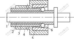
Fig.1 Schematic diagram of backward ball spinning: 1��Mandrel; 2��Spun part; 3��Screw tube; 4��Supporting ring; 5��Conical ring; 6��Ball
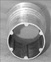
Fig.2 Photograph of spun part
In the course of backward ball spinning, the spinning head, which consists of screw tube, supporting ring, conical ring and balls, is fixed in the chuck of the lathe and turns with the principal axis of the spinning lathe, at the same time, the tubular blank made from aluminum alloy LF2 is mounted on the mandrel and feeds with the mandrel along the axial direction (as shown in Fig.3). Adjusting the relative displacement between supporting ring and screw tube results in the different gaps between the balls and the mandrel, so the different wall thickness reductions are implemented to produce spun parts with various wall thickness and diameter.
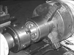
Fig.3 Photograph of backward ball spinning process
The mandrel has the grooves to form the inner ribs. The structure of cross-section of the mandrel is shown in Fig.4. The specific dimension of the cross-section is expressed as follows: b=3.5 mm, c=2 mm, e=2 mm, D=30 mm.

Fig.4 Schematic diagram of cross-section of mandrel
Backward ball spinning is the best plastic working process to form thin-walled tubular parts with longitudinal inner ribs up to now. The quality of inner ribs is one of the critical tasks in obtaining the desired spun workpieces.
3 Basis of finite element formulation
For rigid-plastic materials, the function ![]() is constructed as follows:
is constructed as follows:
![]() (1)
(1)
where �� is the energy function; ![]() is the equivalent stress;
is the equivalent stress; ![]() is the equivalent strain;
is the equivalent strain; ![]() is the equivalent strain rate; �� is the penalty factor;
is the equivalent strain rate; �� is the penalty factor; ![]() is the volume strain rate; Fi is the surface traction and vi is a velocity field.
is the volume strain rate; Fi is the surface traction and vi is a velocity field.
Among admissible velocities that satisfy the conditions of compatibility as well as the velocity boundary conditions, the actual solution makes the first-order variation of the function �� vanish, namely
![]() (2)
(2)
Eqn.(2) is the basic equation for the finite element discretization.
4 General issues of FEM
4.1 Generation of initial velocity field and solution to nonlinear equation
In the simulation of backward ball spinning of thin-walled tubular part with longitudinal inner ribs is involved in the study, the solution of the stiffness equation is obtained iteratively by using the Newton- Raphson method, which needs an initial velocity field. The Newton-Raphson iteration process usually shows a very good property on the condition that the initial velocity field is in the vicinity of the actual solution. However, it may be very difficult to obtain a good initial guess velocity field because the backward ball spinning process is very complex. As another technique for solving a nonlinear equation, the direct iteration method does not require any initial guess velocity and converges fast towards the solution during the earlier stages of iteration. However, as the solution point is approached, the convergence becomes very slow. It is more efficient that the initial velocity field can be obtained by using the direct iteration method and then the final solution can be derived from the Newton-Raphson iteration method. The fundamental principle with respect to the combination of the direct method with the Newton-Raphson iteration method to solve the nonlinear equation is as follows.
Assign the following nonlinear equation:
��(v)![]() (3)
(3)
where K(v) is the matrix dependent on the unknown velocity vector v, and f is the constant vector.
Assume any initial guess solution v0, and the substitution of v=v0 into the equation results in the first approximate correction solution.
![]() (4)
(4)
where [K(v0)]-1 is the inverse matrix of the matrix K(v0).
Repeat the above procedure, and the nth approximate correction solution vn is achieved.
![]() (5)
(5)
The above iteration process is finished when the error norm![]() reaches a specified small value er, namely
reaches a specified small value er, namely
![]() ��er (6)
��er (6)
Once the nth approximate correction solution of the equation is obtained, in order to further achieve the (n+1)th approximate solution vn+1, ��![]() is expressed as Taylor expansion only including the linear term near the solution vn, namely
is expressed as Taylor expansion only including the linear term near the solution vn, namely
��(vn+1)= ��(vn)+![]() (7)
(7)
where d��/dv=KT(v) is the tangent matrix, and then
![]() ��(vn) (8)
��(vn) (8)
![]() (9)
(9)
Repeat the above iteration procedures until the convergence requirement is met.
4.2 Boundary conditions
4.2.1 Velocity boundary condition
The velocity boundary condition for the backward ball spinning of the thin-walled tubular part with longitudinal inner ribs is shown in Fig.5. During FEM simulation, the ball is imparted to an axial velocity vL as well as a tangential velocity vT, but the mandrel is constrained completely. As for the two ends of the tubular blank along the axial direction, the end at the entrance of the ball is free, but the other end is constrained entirely, namely, the axial velocity, radial velocity and tangential velocity are all zero. The outer surface of the tubular blank is free, but the inner surface of the tubular blank is more complex. The inner surface of the tubular blank at the groove of mandrel is free, but the inner surface of the tubular blank at the other section of mandrel is constrained partly, i.e., the radial velocity is zero, but the axial velocity as well as the tangential velocity are not zero.
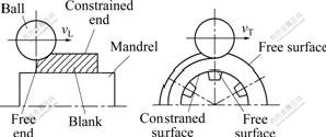
Fig.5 Schematic diagram of velocity boundary condition
4.2.2 Frictional boundary condition
In the course of backward ball spinning of thin- walled tubular part with longitudinal inner ribs, there exists a region along the ball-workpiece interface where the velocity of the deformation material relative to the ball becomes zero. The region is defined as neural region and the location of the region depends on the magnitude of the frictional stress. In order to deal with the problem of the neural region, a velocity-dependent frictional stress is used as an approximation to the condition of constant frictional stress. Therefore, the frictional boundary condition is expressed as
![]() (10)
(10)
where fr is the frictional stress; m is the frictional constant factor; k is the shear yield stress; vr is the sliding velocity of the metal material relative to the ball velocity; v0 is a small positive number compared with vr and takes 10-4 in the paper and l is the unit vector in the opposite direction of relative sliding.
4.3 Determination of penalty factor
The physical interpretation of the penalty factor can be derived from the following formula:
![]() (11)
(11)
where ��m is the hydrostatic stress; �� is the penalty factor and ![]() is the volume strain rate.
is the volume strain rate.
Because of the incompressibility constraint and the invariable hydrostatic stress in the plastic deformation, the function of the penalty factor keeps the volume strain rate close to zero during the plastic deforming. Therefore, the penalty factor will be a very large positive number logically.
The proper choice of penalty factor is important in successful simulation of the backward ball spinning of thin-walled tubular parts with longitudinal inner ribs. Too large a value of the penalty factor results in difficult convergence, while too small a value of the penalty factor leads to unacceptably large volumetric strain rate. The penalty factor takes 104 in the paper.
4.4 Treatment of rigid region
As backward ball spinning is a successive and local plastic deformation process, the rigid zones and the plastic zones simultaneously exist in spinning deformation of thin-walled tubular part with longitudinal inner ribs. The rigid zones are characterized by a very small value of effective strain-rate in comparison with that in the plastic zones. Because the variational principle is based on the plastic deforming body and the assumption of rigid plastic material, the rigid equations show an ill-conditioned phenomenon to lead to no convergence of iterations when the variational principle is used for dealing with the rigid zones. In order to solve the problem and achieve the actual solution, the stress��strain��rate relationship, namely the constitutive equation, is treated as follows.
As for the rigid zones:
![]()
![]() ��
��![]() (12)
(12)
As for the plastic zones:
![]()
![]() ��
��![]() (13)
(13)
where ![]() is an assigned limiting value. The value of
is an assigned limiting value. The value of ![]() has a significant influence on simulation accuracy and convergence of iteration. A too large
has a significant influence on simulation accuracy and convergence of iteration. A too large ![]() value results in a pretty large rigid zone, but a too small
value results in a pretty large rigid zone, but a too small ![]() value leads to poor convergence. The value of
value leads to poor convergence. The value of ![]() takes 10-3 in the simulation mentioned in the paper.
takes 10-3 in the simulation mentioned in the paper.
For the rigid zones, the first term of the basic Eqn.(2) is replaced by
![]()
for
![]() ��
��![]() (14)
(14)
4.5 Convergence criteria
The three convergence criteria are applied in the simulation of backward ball spinning of thin-walled tubular part with longitudinal inner ribs.
4.5.1 Convergence criterion of velocity increment
![]() (15)
(15)
where ��v is a very small positive constant (10-5); ![]() and
and ![]() are the norms of ?v and v, respectively.
are the norms of ?v and v, respectively.
![]() (16)
(16)
![]() (17)
(17)
4.5.2 Criterion of total energy functional increment
![]() (18)
(18)
where ���� is a very small positive constant (10-5).
![]() (19)
(19)
where ��j and ��j-1 are the total energy functions of the jth iteration and the total energy function of the (j-1)th iteration, respectively.
4.5.3 Criterion of stability of rib height
![]() (20)
(20)
where ��H is a very small positive constant (10-5); Hj is the rib height of the jth iteration and Hj-1 is the rib height of the (j-1)th iteration.
4.6 Remeshing
In the course of backward ball spinning of thin-walled tubular part with longitudinal inner ribs, plastic deformation is usually very large. Moreover, the relative motion between the tooling surface and the deforming material is also very large. Such large deformations and displacements lead to the distortion of the element mesh as well as its eventual interference with the tooling, which poses the computational difficulties during FEM simulation. In order to overcome the difficulties, it is necessary to implement a remeshing technique in FEM simulation of backward ball spinning deformation of thin-walled tubular part with longitudinal inner ribs. The most critical tasks in the remeshing technique are to establish mesh distortion criterion and transfer field variables.
4.6.1 Mesh distortion criterion
In the hexahedral element shown in Fig.6, the point P1 is a node of the element, and the points P2, P3 and P4 are adjacent to the point P1. ��1, ��3 and ��4 are unit vectors from P1 to P2, from P1 to P3 and from P1 to P4, respectively.
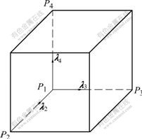
Fig.6 Schematic diagram of mesh distortion
The mesh distortion is judged to arise when ��2, ��3 and ��4 meet the following condition:
(��2����3)? ��4��md (21)
where md is a constant determined according to the actual situation and takes 10-2.
4.6.2 Transfer of field variables
Effective strains are the main field variables transferred from the old mesh system to the new one. Since effective strains are given at the reduced integration point of each element, at first it is necessary to obtain the effective strain values at nodal points through interpolation by using the volume-weighted average method. The effective strain value of the nodal point i surrounded by k adjacent elements is expressed as follows:
 (22)
(22)
where ![]() is the effective strain value at node I;
is the effective strain value at node I; ![]() is the effective strain value at the center of the jth element that surrounds the node i, and Vj is the volume of the jth element that surrounds the node i.
is the effective strain value at the center of the jth element that surrounds the node i, and Vj is the volume of the jth element that surrounds the node i.
After obtaining the effective strain value of all nodes in the old mesh system, it is necessary to determine the location of the nodes of the new mesh system in the elements of the old mesh system. The effective strain values at the nodes in the old mesh system are transferred to the new mesh system by using the following interpolation method:
![]() (23)
(23)
where ![]() is the effective value at the node in the new mesh system;
is the effective value at the node in the new mesh system; ![]() is the element shape function in the old mesh system, and
is the element shape function in the old mesh system, and ![]() is a natural coordinate system.
is a natural coordinate system.
5 Simulation of height of inner ribs
The spinning material used in the experiment is aluminum alloy LF2, of which the constitutive behavior is described as the following equation[18]:
![]() (24)
(24)
In the experiment, the wall thickness of tubular blank is 3.0 mm, the diameter of balls is 20 mm, and the feed ratio is 0.8 mm/r.
Based on the experimental conditions, according to the different wall thickness reduction, the height of inner ribs is simulated. Fig.7 shows the curves of the height of inner rib with respect to wall thickness reduction. It can be seen from the curves that increasing the wall thickness reduction leads to the increase of the height of inner ribs. Because the simulating conditions are based on the simplification of the real spinning process, the calculated results are less than the measured ones. However, if the difference between the experimental conditions and the simulating conditions is neglected, the simulating results conform to the experimental ones. Experiments have proved that by perfectly dealing with the general issues of FEM, FEM can accurately simulate the backward ball spinning of the thin-walled tubular part with longitudinal inner ribs.
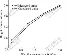
Fig.7 Effect of wall thickness reduction on height of inner rib
6 Conclusions
1) Combining the direct iteration method with the Newton-Raphson iteration technique presents a good approach to obtain the accurate solution and enhance the calculation efficiency in finite element simulation of backward ball spinning of thin-walled tubular part with longitudinal inner ribs. The direct iteration method contributes to obtaining the initial velocity field and then the Newton-Raphson iteration method is more efficient in acquiring the final solution. The frictional stress model is more efficient in handling the neural region and is capable to guarantee the smooth transition of the friction stress in the range near the neural point.
2) Too large a value of the penalty factor results in difficult convergence, while too small a value of the penalty factor leads to unacceptably large volumetric strain rate. The three convergence criteria, namely convergence criterion of velocity increment, criterion of total energy functional increment and criterion of stability of rib height, play a significant role in obtaining the perfect simulation result.
3) By means of reasonable solving the general issues of FEM, rigid-plastic FEM can successfully simulate the height of the inner ribs in backward ball spinning of thin-walled tubular part with longitudinal inner ribs. The calculated values are in good agreement with the measured values.
References
[1] WONG C C, DEAN T A, LIN J. A review of spinning, shear forming and flow forming process [J]. International Journal of Machine Tools and Manufacture, 2003, 43(14): 1419-1435.
[2] PARK J W, KIM Y H, BAE W B. Analysis of tube-spinning processes by the upper-bound stream-function method [J]. Journal of Materials Processing Technology, 1997, 66(1/3): 195-203.
[3] ROTARESCU M I. A theoretical analysis of tube spinning using balls [J]. Journal of Materials Processing Technology, 1995, 54(1/4): 224-229.
[4] ZHANG S H, LI Mao-sheng, XU Yi, KANG D C, LI C Z. Introduction to a new CNC ball-spinning machine [J]. Journal of Materials Processing Technology, 2005, 170(1/2): 112-114.
[5] JIANG Shu-yong, LI Ping, XUE Ke-min. Application of BPANN in spinning deformation of thin-walled tubular parts with longitudinal inner ribs [J]. Journal Central South University of Technology, 2004, 11(1): 27-30.
[6] JIANG Shu-yong, XUE Ke-min, ZONG Ying-ying, YU Lin. Process factors influencing spinning deformation of thin-walled tubular part with longitudinal inner ribs [J]. Trans Nonferrous Met Soc China, 2004, 14(4): 702-707.
[7] JIANG Shu-yong, XUE ke-min, LI Chun-feng, REN Zheng-yi. Spinning deformation criteria of thin-walled tubular part with longitudinal inner ribs [J]. Journal of Wuhan University of Technology (Materials) Science Edition, 2006, 21(4): 169-172.
[8] XU Y, ZHANG S H, LI P, YANG K, SHAN D B, LU Y. 3D rigid-plastic FEM numerical simulation on tube spinning [J]. Journal of Materials Processing Technology, 2001, 113(1/3): 710-730.
[9] XUE Ke-min, LU Yan, ZHAO Xian-ming. The disposal of key problems in the FEM analysis of tube stagger spinning [J]. Journal of Materials Processing Technology, 1997, 69(1/3): 176-179.
[10] XUE Ke-min, LU Yan. Elastic-plastic FEM analysis and experimental study of diametral growth in tube spinning [J]. Journal of Materials Processing Technology, 1997, 69(1/3): 172-175.
[11] LI Ke-zhi, HAO Nan-hai, LU Yan, XUE Ke-min. Research on the distribution of the displacement in backward tube spinning [J]. Journal of Materials Processing Technology, 1998, 79(1/3): 185-188.
[12] HUA F A, YANG Y S, ZHANG Y N, GUO M H, GUO D Y, TONG W H, HU Z Q. Three-dimensional finite element analysis of tube spinning [J]. Journal of Materials Processing Technology, 2005, 168(1): 68-74.
[13] XIA Q X, CHENG X Q, HU Y, RUAN F. Finite element simulation and experimental investigation on the forming forces of 3D non-axisymetrical tubes spinning [J]. International Journal of Mechanical Sciences, 2006, 48(7): 726-735.
[14] XU Y, ZHANG S H, LI P, YANG K, SHAN D B, LU Y. 3D rigid-plastic FEM numerical simulation on tube spinning [J]. Journal of Materials Process Technology, 2001, 113(1/3): 710-730.
[15] JIANG Z Y, LIU X L, LIU X H, WANG G D. Analysis of ribbed-strip rolling by rigid-viscoplastic FEM [J]. International Journal of Mechanical Sciences, 2000, 42(4): 693-703.
[16] ALSAMHAN A, PILLINGER P H. The computer simulation of cold-roll-forming using FE methods and applied real time re-meshing techniques [J]. Journal of Materials Processing Technology, 2003, 142(1): 102-111.
[17] ALVES M L, FERNANDES J L M, RODRIGUES J M C, MARTINS P A F. Finite element remeshing in metal forming using hexahedral elements [J]. Journal of Materials Processing Technology, 2003, 141(3): 395-403.
[18] HE Yang, SUN Zhi-chao, JIN Ying-jun. FEM analysis of mechanism of free deformation under dieless constraint in axial compressive forming process of tube [J]. Journal of Materials Processing Technology, 2001, 115(3): 367-372.
Corresponding author: JIANG Shu-yong; Tel: +86-451-82589468; E-mail: jiangshy@sina.com
(Edited by HE Xue-feng)
