
Trans. Nonferrous Met. Soc. China 26(2016) 2892-2899
Prediction of central bursting defects in rod extrusion process with upper bound analysis method
Amir PARGHAZEH, Heshmatollah HAGHIGHAT
Mechanical Engineering Department, Razi University, Kermanshah 67149-67346, Iran
Received 12 October 2015; accepted 11 March 2016
Abstract:
The prediction of central bursting defects in the rod extrusion process through conical dies using the upper bound analysis is investigated. A kinematically admissible velocity field, including the radial and angular velocity components, is proposed. A new criterion is presented to predict the occurrence of the central bursting defects. Parameter bobt, which represents the risk probability of cracking, is proposed. It is calculated using the shape of the boundary at the entrance by minimizing the total power dissipation during the extrusion process. When bobt is equal to or greater than bcr, central bursting occurs. Furthermore, the quantitative relationships between central bursting defects and process parameters (semi die angle, reduction in area and frictional factor) are studied. The results show that the central bursting defects are affected primarily by the reduction in area and the friction factor. The presented criterion is verified by comparing with the FEM simulation data and the results of the published paper.
Key words:
central bursting defect; upper bound analysis method; rod extrusion process;
1 Introduction
Nowadays, the extrusion process is widely used in the production of industrial components, therefore, concentrating on the final quality of the parts produced by this process is very important. Internal central bursts, which are also called Chevron cracks, are common extrusion processing defects. Ignoring of predicting them will cause both losses of physical injury and property damage or reducing the quality of the final products [1-3]. Usually, it is very difficult to detect central bursting defects by surface inspection. These defects appear through the length of the drawn or extruded parts as shown in Fig. 1 [1,4]. It has been encountered for processing conditions of small area reduction, large die angle, and low friction factor (or combination of these situations) and after severe cold extrusion and drawing of the billet [5-9]. Several experimental studies [10,11] have been performed in order to determine the influence of the main operating parameters (reduction in area, semi die angle, frictional factor and material properties) on the occurrence of central bursts in rod extrusion and wire drawing processes. These studies have allowed to state that these defects are generally restricted to large die angles and small reductions in area. On the other hand, some analytical approaches have been proposed. From initial investigation to predict central bursting defects, AVITZUR [3] presented a model based on the upper bound analysis that could predict central cracks for extrusion and drawing of rigid perfectly plastic materials. He assumed that when central cracks initiate, the required power to do extrusion or drawing process is less than no-central cracking manner. ZIMERMAN and AVITZUR [12] extended Avitzur model [3] for strain hardening metals. MORITOKI [13] used slip line method to predict central cracks and compared his model with Avitzur��s results [3]. WU and LI [14] predicted central bursting defects by using the upper bound method in forward extrusion process through rectangular dies for rigid perfectly plastic materials. ALBERTI et al [15] used numerical approach and ultra-sonic tests to predict central bursting defects in extrusion and drawing processes through conical dies. REDDY et al [16] used hydrostatic stress criterion to predict central bursting defects and die optimization in the forward extrusion process. MORITOKI and OKUYAMA [17] used a method based on plastic instability to predict central bursting defects in plate and rod extrusion. KO and KIM [18] suggested an approach to predict central bursting defects and simultaneous analysis of deformation in extrusion and wire drawing and they applied damage model based on rigid-plastic FEM. SAANOUNI et al [19] predicted central busting defects in rod cold extrusion by coupling ductile damage and thermo-elastoplastic constitutive equations. MCVEIGH and LIU [20] presented a simple cell model based on damage to predict central bursting defects in rod cold extrusion process of aluminum alloy. SOYARSLAN and TEKKAYA [21] investigated the effect of counter pressure on central defects in forward extrusion by using continuum damage mechanics (CDM) approach.  et al [4] extended concept of forming limit curve (FLC) to investigate forming ability in carbon steel and prediction of central bursting defects.
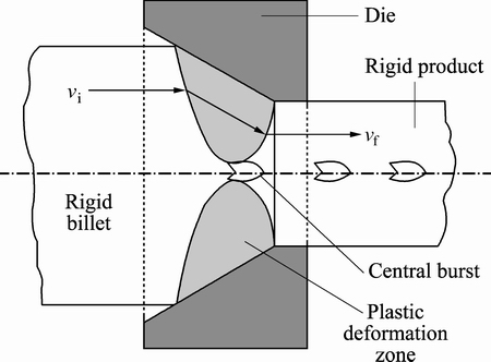
Fig. 1 Internal central bursting defects [1,4]
In this work, a kinematically admissible velocity field is developed to predict the presence of the central bursting defects in the rod extrusion process. Based on the developed velocity field, the critical condition for central bursting defects is obtained. By minimizing the total power formulated from the derived velocity field, the optimized inlet shear boundary and extrusion force are determined. Furthermore, the influence of process parameters, particularly frictional factor on the die wall, on the central bursting defects is determined.
2 Upper bound analysis
According to the upper bound analysis, for a rigid perfectly plastic material, the required power to do a forming process obtained from minimization of the following equation:

 (1)
(1)
where the first term of Eq. (1) indicates internal power of deformation, second and third terms indicate shear power losses along the velocity discontinuity surface and friction power losses along the die-billet respectively and the forth term indicates the power of external traction.
2.1 Kinematically admissible velocity field
The most important subject in the upper bound analysis assumes that velocity discontinuity boundaries and the kinematically admissible velocity field must satisfy volume constancy in deformation zone and boundary conditions. Figure 1 shows the proposed deformation zone and its boundaries for the rod extrusion with the inlet and outlet radii of billet Ri and Rf, respectively, semi die angle of ��, also vi is initial velocity of the billet and vf is velocity of the product.
Equation (2) indicates shear boundaries defined in the spherical coordinates.
 (2)
(2)
where ��i and ��f are shown in Fig. 2, quantity b is the shape parameter of the boundary at the inlet of the deformation region II that can vary from -1 to +1 and �� is the radial position of equal axial components of velocity on the die surface and
 (3)
(3)
Quantity b can be assumed to be negative, zero or positive values. When b is negative, the boundary moves away from the origin O; when b is positive the boundary moves towards the apex of the die, when b is equal to zero, the inlet shear boundary is a cylindrical surface (i.e., g=1) and in this case, Eq. (2) reduces to the shear surface proposed by AVITZUR [3] for flow through a conical die.
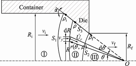
Fig. 2 Deformation zone and shear boundaries
In region I, the material does not deform but moves as a rigid body in the axial direction at velocity vi. In region III the material is already deformed and undergoes no further deformation, moving as a rigid body in the axial direction at velocity vf and from the volume flow balance, it is
 (4)
(4)
Admissible velocity filed in deformation zone (zone II) can be obtained by equilibrium of volume flow as
 (5)
(5)
So, radial velocity component is
 (6)
(6)
The full velocity field for the flow of the material in deformation region II is obtained by invoking volume constancy. Volume constancy in spherical coordinates system is defined as
 (7)
(7)
The strain rate components in spherical coordinates are defined as
 (8)
(8)
For the rod forward extrusion, the peripheral velocity component will be zero, , so angular velocity component is obtained by substituting Eqs. (6) and (8) into Eq. (7), as follows:
 (9)
(9)
where
 (10)
(10)
Therefore, the velocity components in deformation region II are given as
 (11)
(11)
Equation (11) satisfies the incompressibility condition and the boundary conditions on the velocity discontinuity surfaces S1, S2 and on the axis of symmetry,  as well as on the die surface,
  Therefore, it is deemed to be a kinematically admissible field. It is worth noting that
  is assumed in the velocity field for a linear die profile.
2.2 Determination of strain rate components and power terms
The non-vanishing strain rates components in deformation zone II are
 (12)
(12)
The total deforming power required for the process can be split into three parts: 1) internal power of deformation; 2) the power loss due to shear on surfaces of the velocity discontinuities; and 3) the power loss due to friction along the die surface.
2.2.1 Internal power
The internal power in the upper bound analysis for a perfectly rigid von Mises material in deformation zone is
 (13)
(13)
After substitution and simplification, internal power in region II is

 (14)
(14)
2.2.2 Shear power losses
Shear power loss at volume discontinuity boundaries is
 (15)
(15)
For the calculation of the power consumption on each surface of velocity discontinuity, the area of discontinuity must be determined. Therefore, with attention to the geometry of proposed model, Fig. 2, the differential area and amount of the velocity discontinuity of shear surface S1 can be calculated, respectively, by
 (16)
(16)
 (17)
(17)
Thus, the shear power loss on the shear surface S1 is obtained as

 (18)
(18)
Also for the shear surface S2, the differential area and amount of the velocity discontinuity can be obtained, respectively, by
 (19)
(19)
 (20)
(20)
And the shear power loss on the shear surface S2 is obtained as
 (21)
(21)
So, total shear power loss is
 (22)
(22)
2.2.3 Friction power loss
Friction power loss at interface of billet and die in S3 is
 (23)
(23)
where m is the friction factor.
After simplification, friction power loss is obtained as

 (24)
(24)
Finally, external force required to do extrusion process can be obtained by summing the internal power and the power dissipated on the all frictional and velocity discontinuity surfaces as
 (25)
(25)
Also, the relative extrusion pressure is obtained from Eq. (25), which is given by
 (26)
(26)
Integrals appearing in the above equations do not have analytical solution and have been solved by numerical composite Simpson��s method with MATLAB software.
3 Prediction criterion of central bursting defects
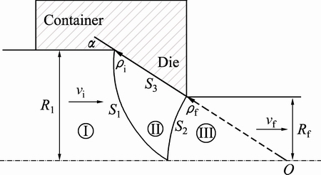
Fig. 3 Geometrical condition to initiate central bursting defects
According to Eq. (25), external force is a function of several parameters including semi die angle, area reduction, friction factor and shape parameter b. Shape parameter b determines inlet boundary shape. It is obvious that the minimum value of external force with respect to b is the required force for extrusion process in the upper bound analysis, which is named here as bopt. On the other hand, according to the geometrical condition, for a value of shape parameter b (named here as bcr), inlet boundary intersects outlet boundary (Fig. 3). We examined the central bursting on the center line in an axially symmetrical deformation, it can be taken that
 (27)
(27)
Thus,
 (28)
(28)
The critical value of b can be obtained as
 (29)
(29)
So, if the obtained shape parameter from the optimization of external force is equal to or greater than the obtained shape parameter from geometrical condition, the central bursting defects initiate. In the simple words, if the optimum shape parameter bopt obtained from Eq. (25) is equal to or greater than the shape parameter bcr obtained from critical geometrical condition (Eq. (29)), the central bursting defects initiate. It can be stated as follows:
 (30)
(30)
4 Results and discussion
4.1 Central bursting defects prediction based on present criterion
In the present criterion, obtaining appropriate value of shape parameter bopt is very important. As previously mentioned, the minimum value of external force with respect to b is the required force for rod extrusion process in the upper bound method. Figure 4 shows the variation of extrusion load versus shape parameter, b, for several reductions of area.
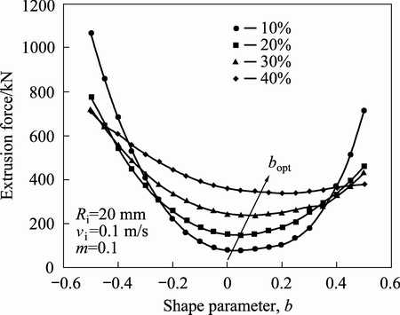
Fig. 4 Variation of extrusion force versus shape parameter b at different area reductions
The central bursting defect criterion is achieved after obtaining the shape parameter from both geometrical condition (bcr) and analytical condition (bopt) and comparing them. Figure 5 shows the conditions of area reduction and semi die angle for preventing central bursting defects. Also, these results have been compared with Avitzur model [3]. It is notable that these results were obtained for rigid perfectly plastic and frictionless situations. Figure 6 shows the effect of friction factor on central bursting defect initiation situations. Also, inlet and outlet boundaries are illustrated in Fig. 7 for different friction factors at area reduction of 40% and semi die angle of 30��.
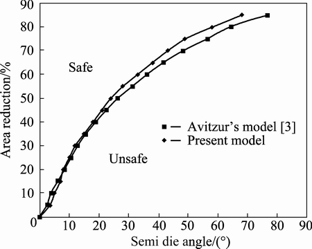
Fig. 5 Safe and unsafe zones for non-strain hardening material
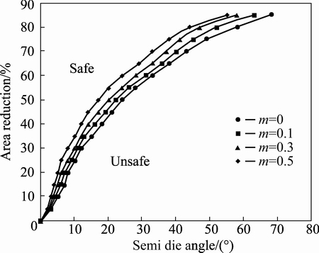
Fig. 6 Effect of friction factor (m) on central bursting defects
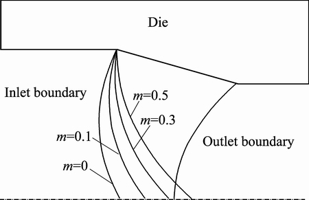
Fig. 7 Inlet and outlet shear boundaries at different friction factors
Table 1 Mechanical properties of 1024 low carbon steel
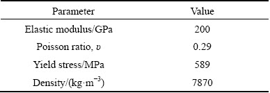
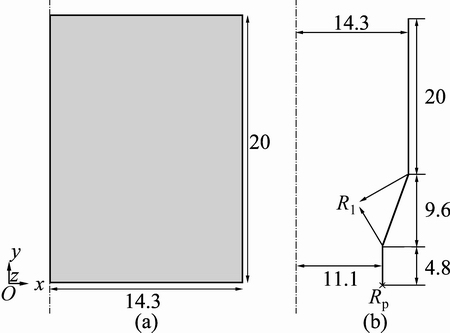
Fig. 8 Geometric dimensions of billet (a) and die (b) (unit: mm)
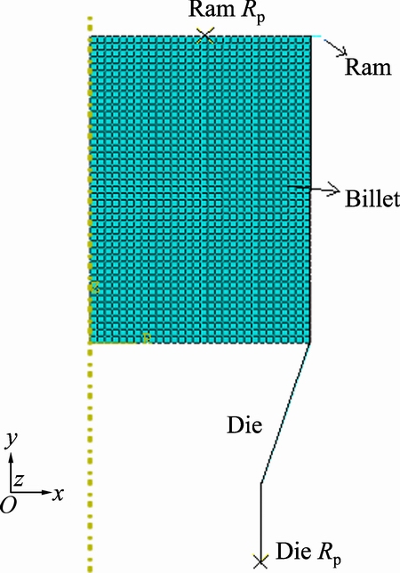
Fig. 9 Assembled model before deformation
4.2 FEM simulation
Finite element model has been used for the investigation of the velocity field in the ABAQUS software. To compare the numerical results with the experimental results of Ref. [3], the analysis was performed on 1024 low carbon steel, and its mechanical and physical properties are shown in Table 1 [3]. According to the upper bound analysis assumptions, the strain hardening is ignored. In order to compare FE model with the present criterion, two different models in both the safe and unsafe zones of Fig. 5 have been established. For this purpose, billet is modeled with axisymmetric deformable description while die and ram are modeled as axisymmetric discrete rigid. Billet and die geometries of Case 1 are shown in Fig. 8 and meshed assembly model is shown in Fig. 9. The extrusion process is modeled in a dynamic explicit step while Arbitrary Lagrangian Eulerian (ALE) adaptive meshing is applied to improving meshing in severe deformation of billet. The fixed boundary condition exerts to the die reference point while ram can be displaced 14 mm along the axis of symmetry with smooth ramp. In this case, a frictionless contact is used in the interaction module between die and billet in order to compare with Ref. [3]. Finally, 1645 linear quadrilateral elements of type CAX4R and 295 linear line elements of type RAX2 are used in order to mesh the billet and die, respectively. The velocity field in the same time of each model shows whether the central bursting defects initiated or not.
Figure 10(a) shows the velocity field in the extrusion process of a billet with 14.3 mm in inlet diameter and 45% reduction of area through a conical die with semi die angle of 20�� (Case 1). The velocity field shows that in this case the central bursting defects do not occur, and the same result is obtained in Fig. 5. In the other model (Case 2), the reduction of area is changed to 40% but die angle remains constant so that Case 2 locates in the safe zone of Fig. 5. The die and billet parameters used for Cases 1 and 2 are listed in Table 2. Also, Fig. 10(b) shows that at the same time of Case 1, the central bursting defects occur. In Fig. 11, the comparison of velocity components obtained from the FEM and the upper bound analysis is illustrated. For this purpose, input data of Case 1 are used. The results obtained for a node located at the radial line and the die angle of 8��. Also, the required relative extrusion pressures for both cases are obtained and illustrated in Fig. 12, which shows when the central bursting defects initiated, less power is required than that when there are no central bursting defects [3].
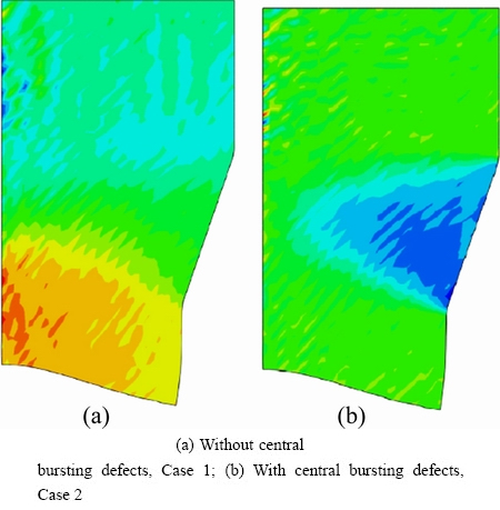
Fig. 10 Velocity filed of extrusion process
Table 2 Die and billet parameters used in FEM simulation
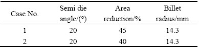
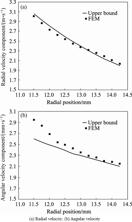
Fig. 11 Comparison of FEM and upper bound analysis velocity components
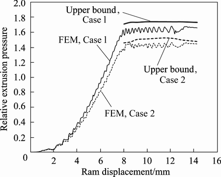
Fig. 12 Comparison of analytical and FEM relative extrusion pressure-displacement curves for Cases 1 and 2
5 Conclusions
1) An analytical method is proposed to predict central bursting defects in rod extrusion process based on the upper bound analysis. For this purpose, a new kinematically admissible velocity field with radial and angular velocity components is presented and then the new shear boundaries including a shape parameter have been obtained. Finally, the new criterion is presented for the prediction of Chevron cracks. Also, the FE modeling was done for typical cases and both the velocity filed and relative extrusion stress were obtained and compared with the upper bound analysis results. It was seen that when the central bursting defects occurred, less power is required than that when there are no central bursting defects. The presented criterion was verified by comparing it with Avitzur model [3] and FEM results.
2) An increase in the frictional factor on the die surface may restrain the growth of the central bursting defects, and the effect of the frictional factor on the die surface on the central bursting defects is very slight.
3) Central bursting defects initiate at large die angles and small reductions in area.
4) The smaller the semi die angle is, the lower the occurrence rate of central bursting defects is.
5) The possibility of central bursting increases with the decrease of die friction factor and forward compression.
6) The advantages of presented criterion to Avitzur��s model are generality of proposed inlet shear boundary and kinematically admissible velocity field which contains radial and angular velocity components. In addition, the presented criterion predicts central bursting defects in simpler mathematical equations than other presented criteria.
Nomenclature
J*
Externally supplied power
b
Parameter of velocity field
bopt
Optimum parameter of velocity field in which extrusion force is minimum
Bcr
Parameter of velocity field in which central bursting defects occur
g(��, ��)
Arbitrarily shape function
m
Friction factor between the material and the die
r, ��, ��
Spherical coordinates system components
r(��, ��)
Radial position of the points with the same velocity
S1, S2
Surfaces of velocity discontinuity
dS1, dS2
Differential area of the velocity discontinuity surfaces
S3
Die surface area
dS3
Differential area of the frictional surface
Ri, Rf
Initial and final radius of billet, respectively

Radial, angular and peripheral components of velocity, respectively
V
Volume of integration
dV
Differential volume of deformation zone
vf
Velocity of final product
vi
Velocity of the material at inlet of the die

Friction power losses along the die surface

Internal power of deformation

Shear power losses along surface of velocity discontinuity
��
Semi die angle
��v
Velocity difference

Normal strain rate components

Shear strain rate components
��
Radial position of a point on the die surface
��i, ��f
Radial distances from virtual cone apex to Inlet and outlet shear boundaries on die surface, respectively
St
Area where the tractions occur
Ti, vi
Traction and velocity applied on St, respectively
Fe
Required extrusion force
Pe
Required extrusion pressure
��o
Average flow stress of the material
References
[1] AVITZUR B. Metal forming; processes and analysis [M]. New York: McGraw-Hill, 1968.
[2] LIM L G, DUNNE F P E. Modelling central bursting in the extrusion of particulate reinforced metal matrix composite materials [J]. International Journal of Machine Tools Manufacture, 1996, 37: 901-915.
[3] AVITZUR B. Analysis of central bursting defects in extrusion and wire drawing [J]. Journal of Engineering for Industry, 1968, 90: 79-91.
[4]  Stress state in forward cold extrusion [J]. Journal for Technology of Plasticity, 2014, 39: 21-27.
[5] RAGAB A R, SAMY S N, SALEH C A R. Prediction of central bursting in drawing and extrusion of metals [J]. Journal of Manufacturing Science and Engineering, 2005, 127: 698-702.
[6] CHOI S. LEE Y S, OH H K. Ductile fracture in axisymmetric extrusion [J]. Journal of Materials Processing Technology, 1998, 74: 263-267.
[7] ARAVAS N. The analysis of void growth that leads to central burst during extrusion [J]. Journal of the Mechanics and Physics of Solids, 1986, 34: 55-79.
[8] REDDY N V, DIXIT P M, LAL G K. Ductile fracture criteria and its prediction in axisymmetric drawing [J]. International Journal of Machine Tools Manufacture, 2000, 40: 95-111.
[9] GURNEY F J, DEPIERRE V. The influence of the interface conditions on the plastic deformation zone and the resultant product integrity in extrusion [J]. Journal of Engineering for Industry, 1974, 97: 912-916.
[10] MCALLEN P, PHELAN P. Ductile fracture by central bursts in drawn 2011 aluminum wire [J]. International Journal of Fracture, 2005, 135: 19-23.
[11] AYADA M, HIGASHINO T, MORI K. Central bursting in extrusion of inhomogeneous materials [J]. Advanced Technology of Plasticity, 1987, 1: 553-558.
[12] ZIMERMAN Z, AVITZUR B. Analysis of the effect of strain hardening on central bursting defects in drawing and extrusion [J]. Journal of Engineering for Industry, 1970, 90: 135-145.
[13] MORITOKI H. The criterion for central bursting and its occurrence in drawing and extrusion under plane strain [J]. International Journal of Plasticity, 1991, 7: 713-731.
[14] WU S, LI M. Analysis of the central cavity of axisymmetric forward extrusion by the upper bound approach [J]. Journal of Materials Engineering and Performance, 1992, 1: 409-414.
[15] ALBERTI N, BARCELLONA A, MASNATA A, MICARI F. Central bursting defects in drawing and extrusion: numerical and ultrasonic evaluation [J]. Manufacturing Technology, 1993, 42: 269-272.
[16] REDDY N V, DIXIT, P M, LAL G K. Central bursting and optimal die profile for axisymmetric extrusion [J]. Journal of Manufacturing Science and Engineering, 1996, 118: 579-584.
[17] MORITOKI H, OKUYAMA E. Prediction of central bursting in extrusion [J]. Journal of Materials Processing Technology, 1998, 80: 579-584.
[18] KO D C, KIM B M. The prediction of central burst defects in extrusion and wire drawing [J]. Journal of Materials Processing Technology, 2000, 102: 19-24.
[19] SAANOUNI K, MARIAGE J F, CHEROUAT A, LESTRIEZ P. Numerical prediction of discontinuous central bursting in axisymmetric forward extrusion by continuum damage mechanics [J]. Computers & Structures, 2004, 82: 2309-2332.
[20] MCVEIGH C, LIU W K. Prediction of central bursting during axisymmetric cold extrusion of a metal alloy containing particles [J]. International Journal of Solid and Structures, 2006, 43: 3087-3105.
[21] SOYARSLAN C, TEKKAYA A E. Prevention of internal cracks in forward extrusion by means of counter pressure: A numerical treatise [J]. Steel Research International, 2009, 80: 671-679.
��������Ԥ������ڼ�ѹ�����е����Ŀ���ȱ��
Amir PARGHAZEH, Heshmatollah HAGHIGHAT
Mechanical Engineering Department, Razi University, Kermanshah 67149-67346, Iran
ժ Ҫ��������������������Բ��ģ���м�ѹʱ�����Ŀ���ȱ�ݽ���Ԥ�⣬�����һ�����������ٶȺͽ��ٶȷ������˶������ٶȳ��������һ���µ�Ԥ�����Ŀ���ȱ�ݲ����ı����������һ����ʾ���ѳ̶ȵIJ���bobt��ͨ����С����ѹ�������ܹ��ʺ�ɢ��������ڴ��ı߽���״���������bobt����bobt��bcrʱ�������Ŀ��������⣬�о������Ŀ���ȱ���뼷ѹ���̲���(ģ�߰��ǡ������С�ʺ�Ħ������)�Ĺ�ϵ��������������ĵ����Ŀ���ȱ����Ҫ�������С�ʺ�Ħ��������Ӱ�졣����������������ķ�����FEMģ�����ݼ������������ݽ����˱Ƚϡ�
�ؼ��ʣ����Ŀ���ȱ�ݣ��������������ļ�ѹ����
(Edited by Wei-ping CHEN)
Corresponding author: Amir PARGHAZEH; Tel: +98-83-34274530; Fax: +98-83-34274542; E-mail: a.parghazeh@razi.ac.ir
DOI: 10.1016/S1003-6326(16)64418-7
Abstract: The prediction of central bursting defects in the rod extrusion process through conical dies using the upper bound analysis is investigated. A kinematically admissible velocity field, including the radial and angular velocity components, is proposed. A new criterion is presented to predict the occurrence of the central bursting defects. Parameter bobt, which represents the risk probability of cracking, is proposed. It is calculated using the shape of the boundary at the entrance by minimizing the total power dissipation during the extrusion process. When bobt is equal to or greater than bcr, central bursting occurs. Furthermore, the quantitative relationships between central bursting defects and process parameters (semi die angle, reduction in area and frictional factor) are studied. The results show that the central bursting defects are affected primarily by the reduction in area and the friction factor. The presented criterion is verified by comparing with the FEM simulation data and the results of the published paper.
