
J. Cent. South Univ. (2012) 19: 128-134
DOI: 10.1007/s11771-012-0981-x![]()
Characteristics of supersonic flow in new type externally pressurized spherical air bearings
WANG Fu-sheng(������), BAO Gang(����)
School of Mechanical and Electrical Engineering, Harbin Institute of Technology, Harbin 150001, China
? Central South University Press and Springer-Verlag Berlin Heidelberg 2012
Abstract:
In order to predict accurately the characteristics of supersonic flow in new type externally pressurized spherical air bearings under large bearing clearance and high air supply pressure, which could decrease their load carrying capacity and stability, a CFD-based analysis was introduced to solve the three-dimensional turbulent complete compressible air flow governing equations. The realizable ��-�� model was used as a turbulent closure. The supersonic flow field near air inlets was analyzed. The flow structures illustrate that the interaction exists between shock waves and boundary layer, and the flow separation is formed at the lower corner and the lower wall around the point of a maximum velocity. The numerical results show that the conversion from supersonic flow to subsonic flow in spherical air bearing occurs through a shock region (pseudo-shock), and the viscous boundary layer results in the flow separation and reverse flow near the shock. The calculation results basically agree with the corresponding experimental data.
Key words:
supersonic flow; spherical air bearings; Mach number; shock wave��
1 Introduction
For high-speed and lightly loaded bearings, air can be used as lubricant, because gases are readily available and the frication is extremely low [1]. Air bearings have been widely used in many applications such as high-precision measuring instrument, space technology, electronic industry and millimeter-sized devices known as micro-electro-mechanical systems (MEMS) [2-3]. But the supersonic flow near the air inlet appears along with the increase of film thickness and air supply pressure. In these cases, the pressure reduction near the inlet becomes very large because of a high velocity of air in the bearing clearance. A significant amount of work has been published on the various parameters affecting the performance of bearings [4-5]. All of these studies have revealed the existence of supersonic flow and undesirable pressure depression of bearings operating under large bearing clearances and high air supply pressures. Therefore, for new type externally pressurized spherical air bearings, the illumination of supersonic flow and the radial pressure distribution in the clearance is very important [6], because it directly affects the load capacity and stability of the bearings.
MORI et al [7-8] studied the pressure distribution near an inlet of an aerostatic thrust bearing with a single inlet. They assumed that the flow in the bearing was a radial flow between two parallel plates and could be divided into three regions. The first region is the supersonic region, the second region is where airflow shifts from supersonic to subsonic flow by shock waves, and the third region is the viscous and isothermal flow region. The three-region theory could predict the pressure distribution near an inlet to some extent, but could not explain the precise flow structure. STAHLER [9] introduced the flow conditions near the inlet. He clarified that a sharp turn at the edge of the inlet in subsonic compressible flow requires very high velocity in the neighborhood of the turn. On the turn side, with a resulting expansion bubble the flow can locally accelerate to a relatively high supersonic velocity downstream of the turn. DOWSON [10] carried out the experimental study, and confirmed STAHLER��s findings and the existence of supersonic flow. However, it is very difficult to get the detailed information of the flow structure from flow visualization because the bearing clearance is very thin.
The computational fluid dynamics (CFD) analysis is considered to be an effective means for investigating the supersonic flow and pressure distribution in the bearing clearances. Recently, YOSHIMOTO et al [6] numerically studied the pressure distribution and supersonic flow in the clearance of circular aerostatic thrust bearings with a single inlet. They computationally investigated the flow structure in the inlet region and concluded that no shock wave occurred in changing from supersonic to subsonic flow. However, few papers clarify the supersonic flow and flow structure near the inlets of spherical air bearings by CFD analysis and experiments. Therefore, in order to predict accurately the characteristics of supersonic flow for new type externally pressurized spherical air bearings, a CFD-based analysis is introduced to solve the three-dimensional turbulent complete compressible air flow governing equations (continuity equation, momentum equations, and energy equation known collectively as full Navier-Stokes equations). The kinetic viscosity of gas is considered as a temperature function. The realizable ��-�� model is used as a turbulent closure for this study. The supersonic flow field near air inlets is analyzed, and the interaction between shock waves and boundary layer is studied in the bearing clearances. The results will be helpful in the study and visualization of the supersonic flow occurring in spherical air bearings.
2 Model of new type air bearings
Figure 1 shows the structure of the new type externally pressurized spherical air bearings. Pressurized air from a constant pressure reservoir flows through the orifice into the bearing clearance. The air flows through the clearance space to the rim of the socket and exhausts to the atmosphere. The ball head radius is denoted by R1 and the ball center is denoted by O1, whereas R2 and O2 refer to the radius and center of the ball socket, respectively. The six proportionally-spaced air inlets have a diameter d0. The air central outlet of ball socket has a diameter d2 and the torsion rod connected to ball head has a diameter d1. The inlet pressure is ps. After being throttled in the torus formed by the air inlet and the air film clearance, the air flow leaves through the air film boundary with the atmospheric pressure pa. The central air film has the thickness of h. The wrap angle of ball socket corresponding to the air intake is denoted by ��1, and the wrap angle of ball socket surface is denoted by ��2.
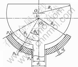
Fig. 1 Structure of new type spherical air bearings
3 Mathematical model
3.1 Governing equations
The conservation form of the Navier-Stokes equations for steady-state three-dimensional compressible flow is solved for the turbulent flow in this work. The Navier-Stokes equations expressed in tensor mark symbols are as follows.
The continuity equation is
![]() (1)
(1)
The momentum equation is

![]() (2)
(2)
The energy equation is
![]()
![]() (3)
(3)
where i =1, 2, 3 and j =1, 2, 3 represent properties in coordinate axis x, y, z directions, respectively; ui and uj are the time-averaged velocity components in the i-direction and j-direction, respectively; u��i and u��j are the fluctuating components in the i-direction and j-direction, respectively; �� is the air density; p is the static absolute pressure; �� is the gas kinetic viscosity; T is the absolute temperature; E is the total energy; ��eff is the effective thermal conductivity.
In Eq. (2), the Reynolds stress ![]() expressed in turbulent viscosity is given by [11-12]
expressed in turbulent viscosity is given by [11-12]
![]() (4)
(4)
where ��t is the turbulent viscosity, which depends on flow state; ��ji is the Kronecker delta symbol (��ji =1 when i=j and ��ji =0 when i��j); k is the turbulent kinetic energy, ![]() .
.
In Eq. (3), E and keff are
![]() (5)
(5)
![]() (6)
(6)
where cp is the constant-pressure specific heat of an ideal gas; �� is the laminar flow thermal conductivity; R is the gas constant; Prt is the turbulent Prandtl number, which takes as 0.85 for air [13]; ![]() is turbulent thermal conductivity.
is turbulent thermal conductivity.
Thus, the pressure p is related to the variables through the gas law:
![]() (7)
(7)
where �� is ratio of specific heats, that is, the ratio of specific heat at constant pressure and specific heat at constant volume. For ideal gas, there is
![]() (8)
(8)
Gas is viscosity compressible fluid, the viscosity coefficient of which is changed with temperature. According to the Sutherland��s law, the gas kinetic viscosity �� is calculated by
![]() (9)
(9)
For air, ��0=1.716��10-5 N��s/m2, S=110.55 K, and T0=273.11 K [13].
3.2 Realizable �� -�� model
In Section 3.1, two more equations are required to determine ��t and �� for problem closure. In this study, turbulence model makes use of the realizable ��-�� model with enhanced wall treatment [14]. This model is somewhat standard in industrial flow calculations and its equation and boundary conditions are not limited by any derivations [15]. In the realizable ��-�� model, the turbulent viscosity ��t is proportional to the dissipation rate of turbulent kinetic energy ��:
![]() (10)
(10)
In Eq. (10), the coefficient C�� is no longer constant as in standard ��-�� model, which is related with strain rate [14]. In the realizable ��-�� model, the transport equations about �� and �� are respectively
![]()
![]() (11)
(11)
![]() (12)
(12)
The coefficients C2, ���� and ���� are empirical constants.
3.3 Mesh generation
The six air inlets are evenly distributed along the circumferential direction, and the ball head is not affected by the horizontal force when it is in the float state. A right-handed Cartesian coordinate system is used with x and y increasing in the radial direction and z pointing away from the lower wall of bearing. Hence, the flow is symmetrical about z axis. In order to reduce the computational time, only one sixth of the physical domain is considered in computations, which is represented by the shaded area in Fig. 2. In order to reduce the truncation error as well as to avoid the numerical divergence, the pyramid mesh is mainly used in mesh generation which suits the large aspect ratio of the mesh element [16]. The mesh generated in entire computational domain is shown in Fig. 3(a). Both the pressure and the velocity vary rapidly near the air inlet and the air central outlet of ball socket, in which the structured hexahedral mesh and local mesh refinement method are used, as shown in Fig. 3(b). This mesh is the best suit when dealing with boundary layers.
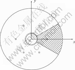
Fig. 2 Computational domain of model
A finite volume method is adopted to discretize the flow governing equations. The viscous and heat transfer terms are centrally differenced; the pressure term is linearly differenced; the density and momentum terms are second order upwind differenced. A SIMPLE algorithm suitable for compressible flows is adopted to solve the discretized governing equations.
3.4 Boundary conditions
To solve the Navier-Stokes equations numerically, the following boundary conditions are assumed.
1) Pressure inlet: in this simulation, the calculations are initiated inside the air inlet. The total pressure and total temperature are prescribed at the air inlet. Let p equal ps and T equal 293 K at the pressure inlet. In order to obtain a satisfactory result, the turbulence intensity in the inlet is assumed to be 7%.
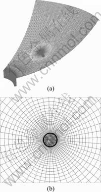
Fig. 3 Computational mesh: (a) Mesh in computational domain; (b) Mesh near air inlet
2) Pressure outlet: The total temperature is prescribed at the air outlet, T = 293 K. And p is set to be the static back pressure, pa, at the pressure outlet. The turbulence intensity in the outlet is assumed to be 7%.
3) Walls: the walls are considered to be in no-slip condition, which are used to limit fluid and solid regions. In this work, a non-equilibrium wall function approach is used to prescribe the flow between the fully turbulent region and the viscous sublayer near the walls.
4) Symmetry plane: let ![]() equal zero and the normal gradients for other variables are set to be zero at the symmetry plane, where n is the surface normal of the symmetry plane.
equal zero and the normal gradients for other variables are set to be zero at the symmetry plane, where n is the surface normal of the symmetry plane.
4 Results and discussion
The structural parameters of the air bearings are set as follows: the ball head radius is R1=50 mm, the ball socket radius is R2=50 mm, the wrap angle of air inlets is ��1=30��, the outer wrap angle of ball socket is ��2=60��, and the air inlet diameter is d0=1.0 mm. The air central outlet diameter of ball socket is d2 =10 mm and the torsion rod diameter connected to ball head is d1=9 mm. The air parameters are set as follows: the ambient pressure is standard atmospheric pressure, the air density is ��=1.226 kg/m3, and the air dynamic viscosity is ��=1.833��10-5 Pa��s.
In order to study conveniently, the supersonic field of the air bearings is analyzed through the center of air inlet in the radial direction, as shown in Fig. 4. It is assumed that the center of air inlet is treated as the base, and the value of �� is positive along the radial outward direction in this wrok.
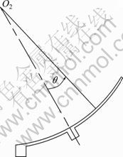
Fig. 4 Analysis section of air bearings
4.1 Pressure distributions and Mach number in different bearing clearances
The recommended values of the empirical constants given by SHIH et al [14] in the realizable ��-�� model are available. The values for the coefficients in Eqs.(11) and (12) are kept the same as those suggested by SHIH et al, i.e., C2=0.9, ����=1.0 and ����=1.2. The calculated pressure distributions on the upper bearing surface are shown in Fig. 5 for the air supply pressure ps=0.9 MPa and bearing clearances h=60, 80 and 100 ��m, respectively. As shown in Fig. 5, in a precise way, the pressure depression occurs immediately after the flow exiting the supply holes in the inlet region and the pressure on the inside of circumference located in air inlets is a bit lower than that on the outside. This is because the smaller open area on the inside leads to the faster airflow velocity, which causes a more pressure steep fall. As can also be seen in Fig. 5, the pressure distributions on the inside and outside of the circumference are similar. Consequently, the flow field on the outside of the circumference taken for example is studied in this work.
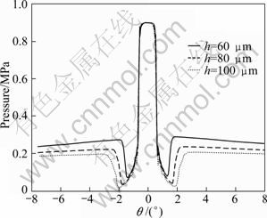
Fig. 5 CFD pressure distributions in different bearing clearances near inlet
Figures 6(a)-(c) show the pressure distribution and the Mach number contours in the bearing clearances for h=60, 80 and 100 ��m, respectively. It can be seen that, the pressure distributions near the inlet show fairly large pressure reduction for each bearing clearance and the numerical results show larger pressure reduction compared with the experimental data near the minimum pressure. However, the CFD pressure distribution and experimental pressure distribution are very similar in the other regions near the inlet. Therefore, the numerical results from realizable ��-�� turbulent model can describe this pressure reduction.
A major characteristic of the high speed airflow in air bearings is the production of a supersonic region near the air inlet, which is followed by a region where the conversion from supersonic flow to subsonic flow takes place. From Fig. 6, it can be seen that after the pressurized air enters the bearing clearances, the air velocity increases along the radial direction. Then, the airflow becomes supersonic flow with a velocity greater than Ma=1 at the central line of bearing clearances. And flow separation is caused at the lower wall near the point of a maximum velocity. At this moment, the Mach number of the airflow begins to reduce. On the other hand, at the beginning of flow separation on the lower wall, the air pressure begins to recover. At the position where the separation on the lower wall disappears, the pressure locally has the maximum value. In flow separation region, the flow width is limited by the separation, the air velocity is gradually reduced, and the airflow is changed from supersonic flow to subsonic, which results in the gradual recovery of the pressure. In this work, the decrease of Mach number is due to the compression wave in process of supersonic flow in bearing clearance and the energy dissipation of boundary layer. The strength of compression wave is weaker. Therefore, the energy dissipation of boundary layer plays a major role with the pressure recovery. In addition, it is seen from the Mach number contours where flow separation regions become larger and air reverse flow is enhanced along with the increase of bearing clearances.
4.2 Details of supersonic flow structures
In this work, the numerical solutions provide a method for detailed investigation of the supersonic flow in the near field of the inlet, which helps in figuring out the reason of pressure depression occurring in bearing clearances. In order to visualize the interactions between the shock waves and boundary layer while the airflow turns into the bearing clearances, the velocity vectors, Mach number and the static pressure contours at the corner region are shown in Fig. 7.
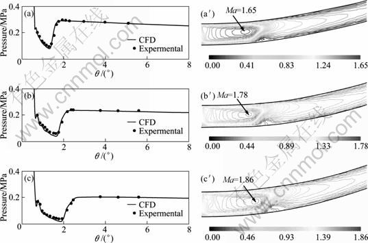
Fig. 6 Pressure distributions (a-c), Mach number contours (a��-c��) near an inlet: (a) ps=0.9 MPa, h=60 ��m; (b) ps=0.9 MPa, h=80 ��m; (c) ps=0.9 MPa, h=100 ��m
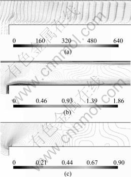
Fig. 7 Interaction between shock waves and boundary layer: (a) Velocity vector (m/s); (b) Mach number contour; (c) Static pressure contour (MPa)
Figure 7(a) shows the existence of a small flow separation region at the lower corner. This makes airflow form a separation bubble in the region near the corner, which extends over about one bearing clearance h from the intake and reattaches to the low surface further downstream. As the airflow turns back toward the lower wall, the Mach number reaches sonic velocity, as shown in Fig. 7(b). Therefore, the curvature of stream line produces expansion waves. While the airflow goes on along the concave part of the lower boundary layer AB compression waves are produced, which is presented in Fig. 8. From Fig. 7(b) and Fig. 7(c), it can be seen that the compression waves merge into a weak oblique shock wave CD. The pressure of the lower wall increases before the point of incidence on the shock wave CD, which causes that the velocity is reduced and the boundary layer is thickened. Because the airflow turns weak, the oblique compression waves are produced at the thickened upper boundary layer edge. The waves merge into the first weak shock wave GH, which is considered as a part of the reflected shock system. The oblique shock wave CD enters the upper boundary layer where it is refracted along DE, and then the weak compression waves from this refraction merge into the weak shock JK, which form the other part of reflected shock system. The airflow after the weak shock is still supersonic flow. Therefore, the curvature of stream line generates the expansion waves, as shown in Fig. 8. Because the incident oblique shock wave is very weak, the flow separation is not generated in the upper wall. In this work, qualitative analysis is gone along for Fig. 7, which is in accordance with the forgone reasonable explanation of the observed interactions between shock waves and boundary layer in the corner region.
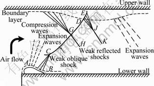
Fig. 8 Sketch map of shock waves and boundary layer interaction in inlet region
As the air flows forward along the radial direction, the flow area enlarges, which leads to the increase of local Mach number and the appearance of supersonic flow region. The compressibility of air results in a more adverse pressure gradient. The lower boundary layer is thickened rapidly, which leads to the decrease of typical flow area, as shown in Fig. 6. The thickening of boundary layer is connected with a succession of compression waves, which are resulted from an interaction between the shock waves and boundary layer. Because of wall friction of bearing surface, the airflow in the boundary layer does not have enough momentum to overcome the adverse pressure gradient, which results in flow separation in the lower boundary layer near the shock waves besides the thickening of boundary layer, as shown in Fig. 6 and Fig. 9. A reverse flow is generated in the separation region and the core stream flows through a succession of forked weak shock waves, with the thickness of main flow becoming rapidly thinner because of the thickening of lower boundary layer. Finally, when the stream lines turn back toward the lower wall, the airflow is changed from supersonic to subsonic flow. The shock system is referred to as a pseudo-shock [1, 8].
As can be seen, the flow in bearing clearance is a complex three-dimensional flow, which is due to the interaction of the boundary layer and shock waves. From Fig. 6, it can be seen that the upstream maximum Mach number in the shock wave region (pseudo-shock) is 1.65, 1.78 and 1.86 for the bearing clearances h=60, 80 and 100 ��m, respectively, which correspond to radial angles ��=1.31��, 1.64�� and 1.84��, and the sonic speeds correspond to radial angle ��=1.64��, 2.37�� and 2.80��, respectively. By calculating the radial distances and comparing with the bearing clearances h, it is found that the shock wave region extends over about eight bearing clearances, which is a bit shorter than the length of shock region of circular gas thrust bearings [17].
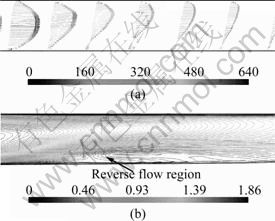
Fig. 9 Details of shock region: (a) Velocity vectors (m/s); (b) Mach number contour
5 Conclusions
1) The supersonic flow in new type spherical air bearings is investigated by solving numerically the three-dimensional turbulent complete compressible air flow governing equations. For large bearing clearances and high air supply pressure, the details of supersonic flow structure in the inlet region show the interaction between shock wave and boundary layer.
2) The flow separation is caused at the lower wall around the point of a maximum velocity, where the pressure recovery occurs. The pressure recovered has the maximum value at the position where the separation vanishes.
3) Due to choking effect, the flow separation is formed at the lower corner, which can lead to the generation of shock waves.
4) The conversion from supersonic to subsonic flow in spherical air bearing occurs through a shock region (pseudo-shock), and the viscous boundary layer results in the flow separation and reverse flow near the shock waves, which spreads over several bearing clearances in radial direction.
References
[1] KAZUYASU M, YOSHIAKI M, HEUY-DONG K. Shock train and pseudo-shock phenomena in internal gas flows [J]. Progress in Aerospace Sciences, 1999, 35: 33-100.
[2] WANG Yun-fei. Air lubrication theory and design of air bearings [M]. Beijing: China Machine Press, 1999. (in Chinese)
[3] LIU Z S, ZHANG G H, XU H J. Performance analysis of rotating externally pressurized air bearings [J]. Proc IMechE Part J: J Engineering Tribology, 1999, 223(4): 653-663.
[4] YUNTANG L, HAN D. Influence of the geometrical parameters of aerostatic thrust bearings with pocketed orifice-type restrictor on its performance [J]. Tribology Int, 2007, 40(3): 1120-1126.
[5] HIKICHI K, GOTO S, TOGO S, ISOMURA K. hydroinertia gas bearings for micro spinners [J]. Journal of Micromechanics and Microengineering, 2005, 15 (9): 228-232.
[6] YOSHIMOTO S, YAMAMOTO M, TODA K. Numerical calculations of pressure distribution in the bearing clearance of circular aerostatic thrust bearings with a single air supply inlet [J]. Journal of Tribology, 2007, 129(4): 384-390.
[7] MORI H. A theoretical investigation of pressure depression in externally pressurized gas lubricated circular thrust bearings [J]. Trans ASME-J Basic Engineering, 1961, 83(1): 201-208.
[8] MORI H, EZUKA H. A pseudo shock theory of pressure depression in externally pressurized circular thrust gas bearings [C]//Proceeding JSLE-ASLE International Lubrication Conference, 1975: 286-294.
[9] STAHLER A F. Further comments on the pressure depression effect in externally pressurized gas-lubricated bearings [J]. ASLE Trans, 1964, 7: 366�C376.
[10] DOWSON D. Laboratory experiments and demonstrations in tribology-externally pressurized air lubricated thrust bearings [J]. Tribology, 1969, 11: 217�C220.
[11] FLUENT Inc. Fluent user��s guide [M]. New Hampshire: Fluent Inc, 2003: (11-2)-(11-9).
[12] VERSTEEG H K, MALALASEKERA W. An introduction to computational fluid dynamics: The finite volume method [M]. New York: Wiley, 1995: 67-75.
[13] WHITE F M. Viscous fluid flow [M]. New York: NcGraw-Hill, 1974: 26-29.
[14] SHIH T H, LIOU W W, SHABBIR A, ZHU J. A new ��-�� eddy-viscosity model for high Reynolds number turbulent flows model development and validation [J]. Comput Fluids, 1995, 24(3): 227�C238.
[15] WANG Fu-jun. Computational fluid dynamics analysis��Principle and application of CFD software [M]. Beijing: Tsinghua University Press, 2004: 120-126. (in Chinese)
[16] MAYRIPLIS D J. Mesh generation and adaptivity for complex geometries and flows [M]// Handbook of Computational Fluid Mechanics. Salt Lake City: Academic Press, 1996.
[17] MOLLER P S. Radial flow without swirl between parallel disks having both supersonic and subsonic regions [J]. Trans ASME-J Basic Eng, 1966, 88(1): 147-154.
(Edited by YANG Bing)
Foundation item: Project(2002AA742049) supported by the National High Technology Research and Development Program of China
Received date: 2010-11-25; Accepted date: 2011-03-07
Corresponding author: WANG Fu-sheng, PhD Candidate; Tel: +86-451-86412443-233; E-mail: wangfs0822@163.com
Abstract: In order to predict accurately the characteristics of supersonic flow in new type externally pressurized spherical air bearings under large bearing clearance and high air supply pressure, which could decrease their load carrying capacity and stability, a CFD-based analysis was introduced to solve the three-dimensional turbulent complete compressible air flow governing equations. The realizable ��-�� model was used as a turbulent closure. The supersonic flow field near air inlets was analyzed. The flow structures illustrate that the interaction exists between shock waves and boundary layer, and the flow separation is formed at the lower corner and the lower wall around the point of a maximum velocity. The numerical results show that the conversion from supersonic flow to subsonic flow in spherical air bearing occurs through a shock region (pseudo-shock), and the viscous boundary layer results in the flow separation and reverse flow near the shock. The calculation results basically agree with the corresponding experimental data.
