

Alternative flat coil design for electromagnetic forming using FEM
M. AHMED1, S. K. PANTHI1, N. RAMAKRISHNAN2, A. K. JHA1,
A. H. YEGNESWARAN1, R. DASGUPTA1, S. AHMED3
1. Advanced Materials and Processes Research Institute(AMPRI), Bhopal-462064, India;
2. India Science Laboratory, GM, Bangalore-560066, India;
3. Maulana Azad National Institute of Technology ( MANIT), Bhopal-462007, India
Received 23 April 2010; accepted 26 September 2010
Abstract:
Electromagnetic forming (EMF) is a high velocity forming process that uses impulse magnetic force. Coil is an important component of EMF system which needs to be designed depending on application. Flat spiral coils are generally used for electromagnetic forming of sheet metals. However, with this type of coil the central portion of the workpiece experiences marginal magnetic force. This leads to in-sufficient deformation at this portion and other problems like air entrapment. In this study, a conceptual design of flat coil was proposed for better distribution of magnetic forces over the workpiece. Comparative analysis of distribution of magnetic force, magnetic field and current density using the proposed and the existing coil designs were carried out using FEM. The result indicates that the proposed coil design produces comparatively better magnetic force distribution over the workpiece. Calculation of self-inductance of such coils was also carried out and was compared with FE simulation.
Key words:
electromagnetic forming; flat spiral coil; sheet metal forming; FEM;
1 Introduction
Electromagnetic forming (EMF) is a high velocity forming process, which utilizes pulsed magnetic force to deform metallic workpiece. Some of the major advantages of this process are reduction in wrinkling and spring back[1], improved formability[2], rapid and high precision forming. Automobile, aerospace, nuclear, air conditioning, medical and home appliance industries are main beneficiary of this technique. The technique was used to join similar and dissimilar metals as well as to deform flat or tubular metallic material (especially light weight) like aluminum, magnesium, etc. EMF system mainly consists of capacitor bank, charging unit, coil, workpiece and die[3]. BELYY et al[4] used the application-based approach to distinguish coils. They classified coils according to their function such as compression coil to compress the tubular component, expansion coil to expand the tube and flat spiral coil that is used in various sheet metal forming processes. In the case of free form bulging of sheet metal using flat spiral coil, a desired magnetic force is not generated in the central portion of the workpiece[5]. This is because of either absence or very less induced eddy current in the central portion of workpiece. PIERRE et al[6] reflected the same stating that there is significant low pressure at the centre due to coil design that leads to less bulging at the centre (Fig.1). If die is used, it leads to entrapment of more air between the die and the workpiece due to short process time, i.e. in ms. This entrapped air additionally prevents the central portion from deforming into desired shape and sometimes leads to problem in tooling and die design.
Work on coils design for flat sheet metal forming are limited as only few researchers have reported their work, and a coil that generates pressure at the central region is not available until now. KAMAL[5] highlighted various types of flat coils and the force profile/pattern generated by them, and worked on a new type of flat coil to generate uniform pressure on the workpiece. He argued that the spatial distribution of forming pressure in electromagnetic forming was controlled by the configuration of the coil. GOLOVASHCHENKO[7] also proposed a new generation coil design along with coil failures mode and its remedies. Field shaper is another tool that is used to modify the electromagnetic field to have desired distribution of the magnetic field and magnetic pressure. YU et al[8] studied the effect of field shaper on magnetic pressure on tubular workpiece and
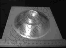
Fig.1 Final shape of deformed sheet using uniform type of coil[6]
found that a greater radial magnetic pressure can be achieved with field shaper than the case without it.
In the present study, a conceptual alternative flat coil design is proposed to modify electromagnetic field so that higher force point can be shifted towards the centre of the workpiece. It is envisaged to improve free- form deformation of sheet around its central portion as well as reduce air entrapment between the workpiece and the die (if used). FE analysis is performed to compare the proposed conceptual coil design with the existing one (i.e. flat spiral coil). This study also deals with calculation of self-inductance of such coil, as no direct model is available to compute it. A mathematical model proposed by GROVER[9] is used with some assumption for inductance calculation of the proposed alternative flat coil and compared with FEA.
2 Conceptual coil design
The electromagnetic field intensity can be intentionally varied from place to place by varying the spacing between the turns/conductors. The proportionality between electromagnetic field intensity and magnetic force can be exploited in the design of electromagnetic forming coils. There will be higher force in the region where the current paths are closely packed as compared to the region where the coil has thick and/ or sparse turns/conductors. This ultimately determines the magnetic force distribution on the sheet and the free-form shape that the sheet metal would take.
Generally used flat spiral coil (henceforth called uniform coil) has uniform cross-section of the turns with equal spacing and constant radial pitch between them. In the proposed conceptual coil (henceforth called non-uniform coil), the electromagnetic field intensity is varied by taking smaller cross-section for the first turn and then increasing the cross section when it moves to the second turn, the third turn and so on. For the sake of comparison between the two types of coil, geometric configurations of similar magnitude are taken. Fig.2(a) shows uniform coil. It can be seen that its radial pitch as well as cross section keeps constant (i.e. P1=P2=P3=P4 and A1=A2=A3=A4=A5). In the proposed conceptual flat coil, the pitch and cross sectional area of turns increase from centre to outer turn along a radial axis as shown in Fig.2(b) (i.e., P1<>2<>3<>4 and A1<>2<>3<>4<>5). The gap (G) values between workpiece and coil, span and cross sectional area of coil in both the cases keep constant.
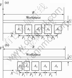
Fig.2 Uniform coil system (a) and non-uniform coil system (b)
3 Finite element simulation
The simulation is carried out to compare magnetic flux distribution, current density and magnetic force on the lower portion of the workpiece for uniform and non-uniform coils. Fig.3 shows a schematic of similar set-up with square shaped work-piece instead of circular. It can be seen that flat sheet is placed below uniform flat coil that is connected to the capacitor bank. Axis symmetric plane considered for 2D FEM analysis is also shown in Fig.3.
3.1 Geometric and material parameters
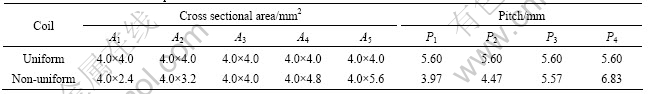
To compare uniform and non-uniform coils, the material properties of workpiece and coil, radius and thickness of workpiece and modeled region are taken identical in the simulation, as discussed in earlier section. The materials for the workpiece and the coil are aluminum and copper, respectively. The material properties and structural parameters used in the simulation are listed in Table 1. The cross sectional areas of the turn and pitch remains constant in uniform coil whereas they increase from centre to outer in non-uniform coil. The cross sectional area and pitch of coil considered in the simulation are given in Table 2. The total cross section area for both types of coils is equal in the considered 2D FE plane.
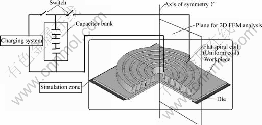
Fig.3 Schematic of electromagnetic forming set-up with simulation zone
Table 1 Material properties and structural parameter

Table 2 Cross sectional area and pitch of coils
3.2 Mesh and boundary condition
Electromagnetic analysis and calculation of self-inductance of uniform and non-uniform coils are carried out using ANSYS, commercial FEA software. The geometry is assumed to be axis-symmetric about one of the axis shown Fig.3 and it is positioned in such a way that Y-axis coincides with symmetry axis. For this purpose, the degree of freedom (Az) is chosen as primary variable in the FE model. Az is a component of magnetic vector potential (MVP) A and is normal to the plane (global XY) in which the FEA model resides.
In line with YU et al[8] and LI et al[10], following assumptions are made in the analysis also:
1) The coil current is distributed equally in its cross-section neglecting skin depth.
2) The material properties (magnetic conductivity and electric conductivity) are isotropic and remain unchanged with time.
3) The displacement current is ignored.
The 2D axis-symmetric FE models with mesh for uniform and non-uniform coil systems are shown in Figs.4 and 5, respectively. The regions numbered with 1, 2, 3 and 4 refer to the near-field air region, the workpiece, the coil, and the far-field air region, respectively. Eight- nodded axisymmetric elements (PLANE53) are used to model workpiece, coil and surrounding air. The workpiece is divided into four layers across thickness. A single layer of 8 noded elements (INFIN110) is used to represent an exterior sub-domain of semi-infinite extent to model far field region. The coil and the workpiece are discretized into 192 elements individually. There are 2 707 elements in total. The exterior line of finite element model (the exterior face) is flagged as infinite surface.
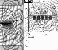
Fig.4 Mesh of FEA model for uniform coil system
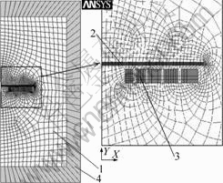
Fig.5 Mesh of FEA model for non-uniform coil system
CIRCU124 element is used to define the sinusoidal current loading in the coil. This element interfaces with electromagnetic finite element of coil are used to simulate coupled electromagnetic-circuit field interaction.
LAL and HILLIER[11] proposed that the waveform of current in forming circuit has the following form, and the same one is applied here.
![]() (1)
(1)
where I0 is the current amplitude; �� is the damping coefficient; �� is the angular frequency (rad/s).
The current excitation is applied through real constant defined as per current waveform shown in Fig.6[12]. The damping coefficient (��) and the angular frequency (��) are slightly different for both the coils because their self-inductance depends on geometric shape. The circuit inductance is neglected in the calculation. The importance of self-inductance and its calculation will be discussed in Section 4. The current waveforms, i.e. discharge current (I) versus time (t) for both uniform and non-uniform coils used in FE simulation are given in Fig.7. The maximum values of current amplitude for uniform and non-uniform coils are 147 kA at 16 ��s and 155 kA at 14 ��s respectively. As calculated, the uniform coil has equal current density (J) for each turn, as shown in Fig.8, whereas non-uniform coil has different current density (J) for different turn, as
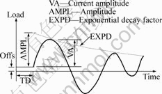
Fig.6 Load functions for independent current sources applied to coil[12]
shown in Fig.9. Here ��x�� represents the turn number starting from centre to outer turn. The current density (Jx) has maximum value for innermost turn, which has a minimum cross sectional area.

Fig.7 Current loading in uniform and non-uniform coils
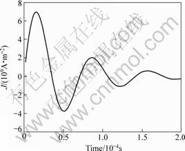
Fig.8 Current density in each turn of uniform coil
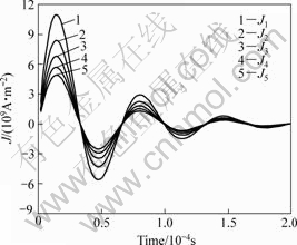
Fig.9 Current density in each turn of non-uniform coil (J1��the 1st turn: innermost, J2��the 2nd turn and so on)
4 Inductance calculation
Self-inductance of coil is a major parameter in designing of electromagnetic forming system as it decides the current waveform of the forming circuit. Many researchers[9, 13-14] attempted to find the self-inductance of various types of coils. The mathematical model given by GROVER[9] can be used to calculate the inductance of uniform coil (flat spiral coil) but no direct mathematical model is available for the proposed non-uniform coil. In this section, an attempt is made to calculate the self-inductance of non-uniform coil by extending/using model given by GROVER[9]. The inductance calculated by Grover model is compared with the one computed using finite element simulation.
4.1 Inductance calculation by Grover model
The mathematical relation for inductance calculation of uniform coil (Fig.10) is given as follows[9]:
![]() (2)
(2)
where L is the inductance of flat spirals coil (��H); N is the number of turns; a is the mean radius of the turn (cm).
Ls=0.001N2ap (3)
![]() (4)
(4)

 (5)
(5)
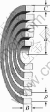
Fig.10 Sectional view of uniform (flat spiral) coil
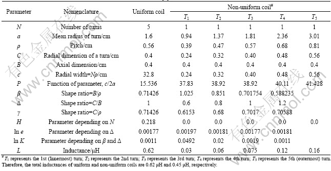
Eq.(2) can be extended to non-uniform coil to get the approximate value of inductance by assuming that each turn of the coil works as a single coil of uniform cross section. The self-inductance of each turn is calculated individually and then added up to get the inductance of non-uniform coil. The details of this calculation for both uniform as well as non-uniform coil are given in Table 3.
4.2 Inductance calculation by FE simulation
Static analysis is performed to find out the self-inductance of uniform and non-uniform coils by a commercial FEA software ANSYS. In the absence of magnetic material, self-inductance is a parameter that is independent of the current and depends only on geometry of the coil[12]. The self-inductance of the coil is calculated by summing the value of inductance stored
Table 3 Inductance calculation for uniform and non-uniform coil[9]
in each element. The self-inductance obtained by Eq.(2) and FE simulation for uniform and non-uniform coil is given in Table 4.
Table 4 Self-inductance of coils (��H)
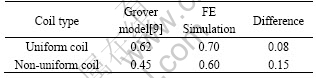
It can be seen from Table 4 that the self-inductance values calculated by Eq.(2) and FE simulation are in a considerable agreement for uniform coil. In the case of non-uniform coil, the self-inductance value using the equation is slightly less as compared with FE simulation result. It may be due to the assumption that each turn has uniform cross section in non-uniform coil. So the Grover model can be used to calculate self-inductance of the proposed conceptual non-uniform coil.
5 Results and discussion
The contours of magnetic filed (B) values at the 1st peak of current for uniform and non-uniform coils are shown in Fig.11. It can be seen from the figure that the maximum magnetic field contours on workpiece for uniform coil system (denoted in Fig.11 as x) is away from the centre as compared with that for non-uniform coil system (denoted in Fig.11 as y). The contours clearly show that not only the region of the maximum value has shifted towards centre in the case of non-uniform coil but also the value is higher. Alternatively, it can be inferred that the magnetic flux density at smaller pitch region is greater than that at bigger pitch region. The maximum values of magnetic field is 21 and 24 T at the 1st peak of current for uniform and non-uniform coil systems respectively. Fig.12 shows the magnetic force vector at the 1st peak of current for uniform and non-uniform coil respectively. It can be seen from the figure that the maximum force vector shifts towards the centre of the workpiece in non-uniform coil. The smaller cross section of inner turns of the non-uniform coil results in higher induced current in the regions of workpiece facing it. A plot between magnetic force (FMAG) on lower element layer of the workpiece and distance from the centre of workpiece at the 1st peak of current is shown in Fig.13 for uniform and non-uniform coils. The forces generated by both the coils are approximately equal to at a distance of 7.5 mm from the centre of the workpiece. The force increases with the increase in distance from the center. It increases more sharply in the case of non-uniform coil as compared with uniform coil upto a distance of 26.5 mm. It is due to the generation of high magnetic flux density in this region, as shown in Fig.11. The magnetic forces generated near the edge region of the workpiece, where the blank holder is placed, show similar trend for both coils. The maximum force of 10.8 kN is achieved at the radius of 18 mm of the workpiece in non-uniform coil as compared with 9.8 kN at 26.5 mm in uniform coil. This
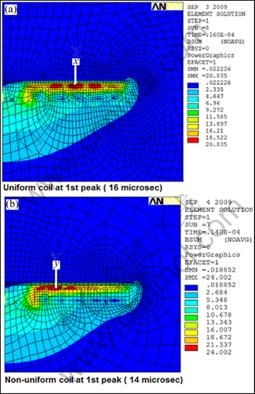
Fig.11 Magnetic flux density contours at the 1st peak of current

Fig.12 Magnetic force vector at the 1st peak
shows a shift of the maximum force point by 8.5 mm approximately towards the centre. It can also be observed that the peak value of FMAG is on the wider area of the workpiece for non-uniform as compared with uniform coil. Thus it allows better forming of the central portion of the workpiece. This may also reduce the problem of air entrapment.
Figs.14 and 15 show magnetic field (B) and current
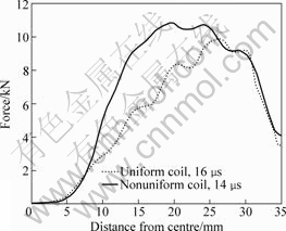
Fig.13 Magnetic force at lower layer of elements of workpiece
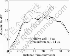
Fig.14 Magnetic field at lower layer of elements of workpiece
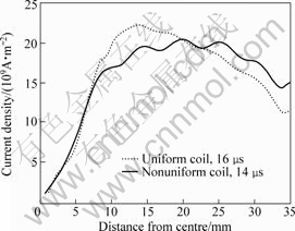
Fig.15 Current density at lower layer of elements of workpiece
density (J) on the lower element layer of the workpiece with respect to distance from centre of the workpiece for both uniform and non-uniform coil systems, respectively, at their 1st peak of current. The magnitude for both B and J are higher towards centre in the case of non-uniform coil as compared with uniform coil. The value of J starts declining for non-uniform coil after 23 mm radius of the workpiece and it is slightly less as compared with uniform coil. But this trend does not reduce the magnetic force on workpiece at that region (Fig.13).
6 Conclusions
1) The conceptual alternative coil (non-uniform coil) designed with varying cross sectional area of turn and pitch is proposed to get enhanced force profile. The proposed conceptual coil changes the force distribution pattern and shifts the maximum force point towards centre of the workpiece.
2) A comparative study of the proposed conceptual coil with the generic flat spiral coil (uniform coil) has been carried out by FE simulation and the results are compared in terms of magnetic force, magnetic flux density and current density. The magnetic force profile generated by non-uniform coil is observed to be better than that by uniform coil. The maximum forces obtained by nonuniform and uniform coils are 10.8 kN at 18 mm radius and 9.8 kN at 26.5 mm radius, respectively. Therefore, a shift of 8.5 mm is achieved by using nonuniform coil, which helps in deformation of sheet in the centre region. This may additionally reduce air entrapment between the workpiece and the die (if used) because the maximum pressure region is shifted towards centre of the workpiece.
3) A method is also proposed to calculate the self-inductance of non-uniform coil using Grover model and the same one is compared with FE analysis. Inductance calculated by the proposed method is slightly less as compared with FE simulation result, which can be attributed to the assumption that each turn of the non-uniform coil works as a single coil of uniform cross section.
Acknowledgment
The authors would like to thank Director, AMPRI Bhopal, India for financial support.
References
[1] PLAZA E I. Electromagnetically impulsed springback calibration [D]. Spain: The University of the Basque Country, 2007.
[2] DEHRA M S, VOHNOUT V J, DAEHN G S. Formability of steel sheet in high velocity impact [J]. Journal of Materials Processing Technology, 2005, 168: 390-400.
[3] BRUNO E J. High-velocity forming of metals [M]. ASTME, 1968.
[4] BELYY I V, FERTIK S M, KHIMENKO L T. Electromagnetic metal forming handbook (A Translation of the Russian Book: Sprvochnik Po Magnitno-impul�� Snoy Obrabotke Metallov). ALTYNOVA M M, DAEHN G S. Columbus: The Ohio State University Press, 1996.
[5] KAMAL M. A uniform pressure electromagnetic actuator for forming flat sheets [D]. Columbus: The Ohio State University, 2005.
[6] PIERRE L, COOK G, ASHCRAFT C. Introduction of an electromagnetism module in LS-DYNA for coupled mechanical thermal electromagnetic simulations [C]//Proceedings of 3rd International Conference on High Speed Forming. Dortmung, Germany, 2008: 85-96.
[7] GOLOVASHCHENKO S F. Material formability and coil design in electromagnetic forming [J]. Journal of Materials Engineering and Performance, 2007, 16(3): 314-320.
[8] YU H, LI C, ZHAO Z, LI Z. Effect of field shaper on magnetic pressure in electromagnetic forming [J]. Journal of Materials Processing Technology, 2005, 168: 245-249.
[9] GROVER F W. Inductance calculations [M]. New York: Dover Publications, Inc., 2004.
[10] LI C, ZHAO Z, LI Y W, YANG Y. Numerical simulation of magnetic pressure in tube electromagnetic bulging [J]. Journal of Materials Processing Technology , 2002, 123: 225-228.
[11] LAL G K, HILLIER M J. The electrodynamics of electromagnetic forming [J]. International Journal of Mechanical Science, 1968, 10: 491-500.
[12] ANSYS Release 11.0. ANSYS low frequency electromagnetic analysis guide [R]. 2007.
[13] THOMPSON M T. Inductance calculation technique- Part-I: Classic model [J]. Power Control and Intelligent Motion, 1999, 25(12): 40-45.
[1] THOMPSON M T. Inductance calculation technique��Part-II: Approximation and handbook methods [OJ/OL]. [1999] Power Control and Intelligent Motion, www.thompsonrd.com/induct2.pdf.
��������Ԫ����Ƶ�ų��εķǾ�����Ȧ
M. AHMED1, S. K. PANTHI1, N. RAMAKRISHNAN2, A. K. JHA1,
A. H. YEGNESWARAN1, R. DASGUPTA1, S. AHMED3
1. Advanced Materials and Processes Research Institute(AMPRI), Bhopal -462064, India;
2. India Science Laboratory, GM, Bangalore-560066, India;
3. Maulana Azad National Institute of Technology ( MANIT), Bhopal-462007, India
ժҪ����ų�����һ��ʹ�������������ٳ��εĹ��ա���Ȧ�ǵ�ų���ϵͳ�е�һ����Ҫ��ɲ��֣���Ҫ����ʵ��Ӧ���������ơ�����������Ȧͨ�����ڽ��������������С�Ȼ������������Ǿ�����Ȧ���������IJ�λ�ĵ���������Ӷ����±��β���ֲ��һ�������������֣����������ݡ���ˣ����һ����ƷǾ�����Ȧ�ĸ���Ա������ķֲ������ȡ���������Ԫ��������ķǾ�����Ȧ�봫ͳ�ľ���������Ȧ�͵�����ķֲ����ų��͵����ܶȽ��бȽϡ�����������Ǿ�����Ȧ�ĵ�����ֲ������ȡ�����������Ȧ�ĸ�Ӧǿ�Ȳ������˱Ƚϡ�
�ؼ��ʣ���ų��Σ�������Ȧ��������ij��Σ�����Ԫ��
(Edited by YANG Hua)
Corresponding author: M. AHMED; Tel: 0091-9926339500; E-mail: meraj.ampri@gmail.com
DOI: 10.1016/S1003-6326(11)60759-0
