
YJ. Cent. South Univ. Technol. (2009) 16: 0482-0487
DOI: 10.1007/s11771-009-0081-8
![]()
Constitutive equations and finite element implementation of
strain localization in sand deformation
HUANG Lin-chong(���ֳ�)1, 2, XU Zhi-sheng(��־ʤ)1, WANG Li-chuan(������)1
(1. School of Civil and Architectural Engineering, Central South University, Changsha 410075, China;
2. Department of Civil and Environmental Engineering, Northwestern University, Evanston, IL 60208, USA)
Abstract:
A recently proposed model coupling with the solid-fluid of the saturated sand was utilized to study the deformation band. Based on the critical state plasticity model by Borja and Andrade, the hydraulic conductivity tensor was naturally treated as a function of the spatial discretization matrix about the displacement and the stress field, allowing a more realistic representation of the physical phenomenon. The fully Lagrangian form of the Darcy law was resolved by Piola algorithm, and then the flow law was gained, leading to the implementation of a modified model of the saturated sand. Then the criterion for the onset of localization was derived and utilized to detect instability. The constitutive model was implemented in a finite element program coded by FORTRAN, which was used to predict the formation and development of shear bands in plane strain compression of saturated sand. At last, the formation mechanism of the shear band was discussed. It is shown that the model works well, and the simulation sample bifurcates at 1.18% axial strain, which is in a good qualitative agreement with the experiment. The pore pressure greatly affects the onset and development of the deformation band, and it obviously increases around the localization-prone regions with the direction toward the outer side of the normal of the shear band, while the pore stress flows nearly horizontally and is distributed equally far away the shear band region.
Key words:
constitutive equations; deformation band; finite elements; hydraulic conductivity; sand��
1 Introduction
The highly localized deformation band of sand under extreme loading, in the form of narrow zones of intense shearing, is a phenomenon commonly observed in soils and rocks. It is well known that appearance of bands of intense localized deformation significantly reduces the load-carrying capacity of the structure that develops them [1-4]. Deformation band in saturated sand is of particular interest in geotechnics due to liquefaction and flow slide susceptibility.
The quantification of shear band deformation dated back to the 1960s when ROSCOE and BURLAND [5] investigated local void ratio evolution with X-ray and ��-ray techniques during simple shear tests on dry sand. Several recent studies aided by new experimental methods have traced the whole process of deformation in sand by quantifying the strain field and providing valuable insight into the phenomenon of shear band formation [6-9]. Observations confirm that the shear band is not a line of slippage of sand, but has a certain width that seemingly depends on the grain size of sand, and is subjected to variation during the formation process.
Considerable progress has been made through the application of the finite element method with constitutive equations for finite deformations, and the problem of shear band formation has been studied by applying the bifurcation theory, in which the shear band is modeled as a plane of discontinuity of the velocity gradient. The theory is based on the constitutive equation for the inelastic, finite deformation of the material [10-16]. The associated instability is interpreted in the sense that, at the critical point, there exists a solution with discontinuity in the velocity gradient other than the uniform and continuous solution. At this bifurcation point, the governing field equation loses its ellipticity. Thus the problem is reduced to find conditions under which the governing field equations for the rate of deformation cease to be elliptic. While theoretical work based on the bifurcation theory has enhanced the understanding of shear band formation, but it has not addressed the realistic representation of the physical phenomenon to the pore character of the sand, that is, the model coupling with fluid-solid. Furthermore, the study of the localization condition on saturated sand is also seldom.
The Mohr-Coulomb yield condition is widely used in soil mechanics to determine the stress required for flow of a granular material; however, the flow rule is
generally not agreed upon. In this work, based on the critical state plasticity model proposed by BORJA and ANDRADE [17], BORJA and TAMAGNINI [18], the hydraulic conductivity tensor was treated as a function of the spatial discretization matrix about the displacement and the stress field. Also, the fully Lagrangian form of the Darcy law was resolved by Piola algorithm and then the flow law was gained, leading to the implementation of a modified model of the saturated sand.
2 Constitutive model
2.1 Additive decomposition of velocity gradient
The kinematics of a granular material is characterized by the hypothesis that the velocity gradient L is additively decomposable into an elastic part and a plastic part:
L=Le+Lp (1)
where superscripts e and p are for elastic state and plastic state, respectively. L��![]() , where
, where ![]() denotes the spatial velocity gradient, and plastic velocity gradient Lp is the macroscopic representation of the incremental plastic deformation that arises at the microscale because of sliding and rolling of contacting granules relative to each other. Elastic velocity gradient Le is the accompanying velocity gradient, which causes a change in Cauchy stress T, whereas the plastic velocity gradient does not cause a change in the stress.
denotes the spatial velocity gradient, and plastic velocity gradient Lp is the macroscopic representation of the incremental plastic deformation that arises at the microscale because of sliding and rolling of contacting granules relative to each other. Elastic velocity gradient Le is the accompanying velocity gradient, which causes a change in Cauchy stress T, whereas the plastic velocity gradient does not cause a change in the stress.
2.2 Constitutive equation for stress
Let D��sym L, De��sym Le, Dp��sym Lp; We��skw Le, Wp��skw Lp. skw A or sym A denote the skew-symmetric or symmetric part of a second order, where De and Dp denote the elastic and plastic stretching, respectively, while We and Wp denote the elastic and plastic spins, respectively. For the typically small elastic stretches observed in granular materials, the evolution equation for Cauchy stress T is taken as
![]() (2)
(2)
where ![]() is a fourth-order elasticity tensor, which is possibly dependent on stress T and relative density ��,
is a fourth-order elasticity tensor, which is possibly dependent on stress T and relative density ��, ![]() with ��=��/��s, where �� and ��s are the mass densities of the granular material and solid granules.
with ��=��/��s, where �� and ��s are the mass densities of the granular material and solid granules.
2.3 Yield condition
Consider the stress invariants of Kirchhoff stress tensor [17-18]
![]() (3)
(3)
![]() (4)
(4)
��=��-pI (5)
where �� is the deviatoric component of stress tensor ��, quantity p is called the mean normal stress and is assumed negative throughout, while quantity q is called shear stress, and I is the second-order identity tensor.
From these three stress invariants we construct a yield surface of the form
F(��, pi)=F(p, q, ��, pi)=q+��p��0 (6)
2.4 Consistency condition
The yield condition F in this analysis is the classical Coulomb-Mohr condition
![]() (7)
(7)
where F is deformation gradient tensor, H is plastic modulus, ��?�� denotes an inner product of two second-order tensors, and![]() is the consistency parameter.
is the consistency parameter.
3 Modified model with hydraulic conduc- tivity tensor
Neglecting the plastic spin Wp=0 [19], the flow rule can be written as
![]() (8)
(8)
In the porous media, the relative flow vector q is related to the Cauchy pore pressure via the Eulerian form of the classical Darcy law [15, 20]
![]() (9)
(9)
where k��1k��f/�� is the isotropic hydraulic conductivity tensor, scalar k is the intrinsic permeability of the porous media, �� is the dynamic viscosity of the fluid, g is the gravitational acceleration constant, and ��f�Ԧ�fg is the scalar specific weight of the fluid.
For completeness of presentation, the Lagrangian expression for Darcy law is obtained by recalling the Piola transform of the relative flow vector,
Q=JF-1?q (10)
From Eqns.(9) and (10), the following equation can be obtained:
![]() (11)
(11)
since ![]() the fully Lagrangian form can be written as
the fully Lagrangian form can be written as
![]() (12)
(12)
where K=JF-1?k?F-t is the pull-back hydraulic conductivity tensor.
4 Localization condition
In general, to saturated media, it is possible to write down an expression relating the total stress rate and the rate of deformation for the granular matrix, i.e. ��P=A:��F, where A is the first tangent operator with components:
![]() (13)
(13)
Consequently, according to the continuity of total tractions across the band:
||A?��F||?N=0 (14)
where ||A|| is the jump operator across the band and N is the normal to an impending shear band in the reference configuration.
From Ref.[17], ![]() where ||V|| is the material velocity jump, h0 is the thickness of the planar band in the reference configuration, and
where ||V|| is the material velocity jump, h0 is the thickness of the planar band in the reference configuration, and ![]() denotes a juxtaposition, e.g.
denotes a juxtaposition, e.g. ![]()
So, the continuity condition shown in Eqn.(14) can be written as
A?||V||/h0=0 (15)
When the localization deformation occurs, h0��0, then a necessary condition for localization is
det A=0 (16)
where det A denotes Jacobian determinant of A.
5 Numerical simulation
According to the constitutive model framework and the numerical implementation described above, a finite element program was coded by FORTRAN, which was used to predict the formation of shear bands in plane strain compression.
5.1 Computational model
The simulation presented in this section used Q9P4 elements, indicating that the elements consisted of two-dimensional quadrilaterals with 9 displacement nodes and 4 pore pressure nodes, as shown in Fig.1. The plane strain test simulation was performed on a 50 mm��100 mm sample with 5��10 isoparametric element meshes, as shown in Fig.2. This kind of finite element was shown to satisfy the Babuska-Brezzi stability condition and hence avoided stability problems associated with consolidation of porous media [16].
The boundary conditions for this simulation were as follows. The top and bottom faces of the sample were supported on rollers with the bottom left corner fixed with a pin for stability. The bottom face was constrained from displacing in the vertical direction, whereas the top

Fig.1 Q9P4 element with 9 displacement nodes and 4 pore pressure nodes
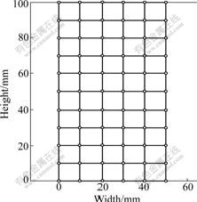
Fig.2 Computational model of plane strain test
face was limited by a vertical displacement responsible for compacting the sample in the axial direction. The loading rate factor��time function was shown in Fig.3, with scaling factor ��=2 cm for vertical compression f(t), so the loading factor d(t)=0.02 f(t). At the same time, the lateral faces were confined with an initial pressure of 100 kPa to simulate the confining pressure in a plane strain device. As for the boundary conditions associated with the flow equations, all faces of the sample were no-flow boundaries, providing a globally undrained condition. This condition is equivalent to have an impermeable membrane surrounding the specimen, which is typically used in undrained compression tests in the laboratory [17-21]. A pictorial representation of the boundary condition is shown in Fig.4.
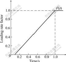
Fig.3 Loading rate factor��time function curve of sample
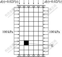
Fig.4 Boundary condition of computational model
5.2 Computational parameters
The material in this simulation is Erksak sand [22], and its parameters are summarized in Table 1.
Table 1 Summary of material parameters

5.3 Computational results and analysis
The dilation behavior of the sand specimen can be clearly observed in Figs.5(a)-(d), where the contours for the deviatoric strains are plotted against the deformed finite element mesh at axial strain of 0.80%, 1.00%, 1.18% and 2.00%, respectively. In these figures, the meshes are the model contours before the deformation. In the initial loading state, the specimen is compressed axially and moved laterally toward the right face, as the fixed pin at the bottom of the left corner, which is similar to the phenomenon observed in the laboratory [23]. As the increment of the loading time, the deviation strains in some elements of the specimen increase locally, under the effect of the pore stress, which leads to two obvious conjugate deformation bands. After the onset of the bands, because of the shear stress, the upper of the deformation band moves toward left, whereas the bottom of the band moves toward right all the time with the fixed pin at the bottom of the left corner. At last, one macroscopical shear band is formed under the development of the sliding, and the location and the angle of the shear band are both shown to be in good quantitative agreement with the experimental results [12, 22, 24].
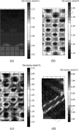
Fig.5 Contours deviatoric strains with superimposed flow vector at different axial strains: (a) 0.80%; (b) 1.00%; (c) 1.18%; (d) 2.00%
According to the formation and development of the deformation band shown in Fig.5, the formation mechanism of the shear band can be seen as the process of the strain concentration and the volume dilation of the elements in the bands, under the effect of the pore pressure. A pictorial representation of this mechanism is shown in Fig.6. Because of the volume dilation, the deformation in this special element will be driven consequentially, along the direction with the weakest constraint. In this simulation, the volume dilation will be forced to move toward the right face (the weakest constraint), and the pictorial representations of the deformation are shown in Figs.5(a)-(c). The pore stress in the specimen increases together with the increment of the plastic deformation, and the value gets large abruptly along with the macroscopical shear band direction, when the localization deformation begins, shown in Fig.5(d), leading to one single macroscopical shear band with the top towards left and the bottom towards right.
The stress��strain curve of the sand deformation is plotted in Fig.7. In this figure, the reactive stresses at the top face of the sample are plotted against the nominal strain. It can be seen that the sample bifurcates at about 1.18% axial strain, and then the onset of the localization is produced.

Fig.6 Sketch of shear band formation mechanism
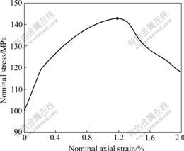
Fig.7 Stress��strain curve for sand sample
Localization here is defined as the first time the first tangent operator A loses positive definiteness at any Gauss point in the sample, according to the localization condition shown in Eqn.(16). Based on the localization criterion, the element where the sample is localized for the first time is shown in Fig.4 and referred to as element E. The determinant function for the first tangent operator A at element E against the axial strain is plotted in Fig.8. Localization occurs around 1.18% nominal axial strains when the Jacobian determinant of A goes negative for the first time, which is consistent to the stress��strain curve shown in Fig.7.
In Fig.5, the white arrows denote the fluid flow field is created by the higher pore pressure, and then develops the localization-prone regions. It is clear that the flow field is not obvious before the onset of the localization, and the pore pressure increases in these localization-prone regions with the increase of the deviatoric strain. At the same time, the fluid flow field diffuses toward outside.
Here, the fluid field distribution and the pore stress development are analyzed. The contours of Cauchy pore stresses at axial strains of 0.80%, 1.00%, 1.18% and 2.00% are plotted in Fig.9. In the initial state of the plastic deformation, the pore stress is about 32 kPa, and the stress at the bottom of the specimen is larger than that at the upper, but the stresses are distributed equably. Before the onset of the localization, the pore stress in the specimen increases together with the increment of the plastic deformation. What is more, the value gets large obviously along with the macroscopical shear band direction shown in Fig.9(c), when the localization deformation begins. At last, the pore stress gets to about 45 kPa when the axial strain is 2.00%. However, the pore stress even reaches more than 90 kPa around the shear band. Around the shear band region, it is observed that the pore stress is in the direction of the outer side of the normal of the shear band, whereas the pore stress flows nearly horizontally far away the shear band region.
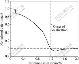
Fig.8 Curve of determinant function vs axial strain at mesh E

Fig.9 Contours of pore pressure at different axial strains: (a) 0.80%; (b) 1.00%; (c) 1.18%; (d) 2.00% (unit: kPa)
6 Conclusions
(1) A predictive finite element model is presented to capture the deformation band in saturated sand using critical state plasticity theory and nonlinear finite element analysis. It is implemented in FORTRAN by writing finite element program, which is used to predict the formation of deformation bands in plane strain compression.
(2) The model coupling with sand-fluid works well. By introducing the hydraulic conductivity tensor, the model provides a more realistic mathematic representation of the shear band, which is in an encouraging quantitative agreement with experiments.
(3) The pore pressure greatly affects the formation and development of the deformation band due to the coupling of the pore media and the fluid flow.
(4) The pore pressure obviously increases around the localization-prone regions with the direction toward the outer side of the normal of the shear band, whereas the pore stress flows nearly horizontally and is distributed equally far away the shear band region.
References
[1] ALSINY A, VARDOULAKIS I G, DRESCHER A. Deformation localization in cavity inaction experiments on dry sand [J]. G��otechnique, 1992, 42(3): 395-410.
[2] SHI Cheng-hua, HUANG Lin-chong. Calculation of soil deformation in area of disturbance due to pipe-jacking construction [J]. Journal of Central South University: Science and Technology, 2005, 36(2): 323-328. (in Chinese)
[3] ZHAOMing-hua, LIUDun-ping, ZHANGLing, JIANGChong. 3D finite element analysis on pile-soil interaction of passive pile group [J]. Journal of Central South University of Technology, 2008, 15(1): 75-80.
[4] ANAND L. Plane deformations of ideal granular materials [J]. Journal of the Mechanics and Physics of Solids, 1983, 31(2): 105-122.
[5] ROSCOE K H, BURLAND J H. On the generalized stress�Cstrain behavior of ��wet�� clay [C]// Engineering Plasticity. Cambridge: Cambridge University Press, 1968: 535-609.
[6] LANDIS E N, NAGY E N, KEANE D T. Microstructure and fracture in three dimensions [J]. Engineering Fracture Mechanics, 2003, 70(7): 911-925.
[7] OTANI J, MUKUNOKI T, OBARA Y. Characterization of failure in sand under triaxial compression using an industrial X-ray scanner [J]. International Journal of Physical Modelling in Geotechnics, 2002, 34(1): 15-22.
[8] MEES F, SWENNEN V, GEET M, JACOBS P. Applications of X-ray computed tomography in geosciences [M]. London: Geological Society, Special Publications, 2003.
[9] LENOIR N, BORNERT M, DESRUES J, BESUELLE P, VIGGIANI G. 3D digital image correlation applied to X-ray micro tomography images from triaxial compression tests on argillaceous rock [J]. Strain, 2007, 43(3): 193-205.
[10] DESRUES J, CHAMBON R, MOKNI M, MAZEROLLE F. Void ratio evolution inside shear bands in triaxial sand specimens studied by computed tomography [J]. G��otechnique, 1996, 46(3): 529-546.
[11] KETCHAM R A, CARLSON W D. Acquisition, optimization and interpretation of X-ray computed homographic imagery: Applications to the geosciences [J]. Computers and Geosciences, 2001, 27(4): 381-400.
[12] RICE J R. The localization of plastic deformation [C]// KOITER W T. Theoretical and Applied Mechanics. Amsterdam, 1976: 207-220.
[13] QIAN Jian-gu, HUANG Mao-song. An analytical solution for criterion of onset of strain localization of soils [J]. Rock and Soil Mechanics, 2005, 26(3): 432-436. (in Chinese)
[14] HUANG Mao-song, QIAN Jian-gu, WU Shi-ming. A homogenization approach to localized deformation in saturated soils [J]. Chinese Journal of Geotechnical Engineering, 2002, 24(1): 24-28. (in Chinese)
[15] WANG L B, FROST J D, LAI J S. Three-dimensional digital representation of granular material microstructure from X-ray tomography imaging [J]. Journal of Computing in Civil Engineering, 2004, 18(1): 28-35.
[16] BELYTSCHKO T, LIU W K, MORAN B. Nonlinear finite elements for continua and structures [M]. West Sussex: John Wiley and Sons Ltd, 2000.
[17] BORJA R I, ANDRADE J E. Critical state plasticity. Part VI: Meso-scale finite element simulation of strain localization in discrete granular materials [J]. Computer Methods in Applied Mechanics and Engineering, 2006, 195(37/40): 5115-5140.
[18] BORJA R I, TAMAGNINI C. Cam-clay plasticity. Part III: Extension of the infinitesimal model to include finite strains [J]. Computer Methods in Applied Mechanics and Engineering, 1998, 155(1/2): 73-95.
[19] DAFALIAS Y F. Plastic spin: Necessity or redundancy [J]. International Journal of Plasticity, 1998, 14(9): 909-931.
[20] BEAR J. Dynamics of fluids in porous media [M]. New York: Elsevier Publishing Company Inc, 1972.
[21] ANDRADE J E, BORJA R I. Capturing strain localization in dense sands with random density [J]. International Journal for Numerical Methods in Engineering, 2006, 67(11): 1531-1564.
[22] JEFFERIES M G. Nor-sand: A simple critical state model for sand [J]. G��otechnique, 1993, 43(1): 91-103.
[23] CHANG C S, MATSUSHIMA T, LEE X. Heterogeneous strain and bonded granular structure change in triaxial specimen studied by computer tomography [J]. Journal of Engineering Mechanics, 2003, 129(11): 1295-1307.
[24] XU Lian-min, WANG Xing-ran. Numerical simulation of shear band in clayey soils using finite deformation theory [J]. Chinese Journal of Geotechnical Engineering, 2004, 26(2): 225-228. (in Chinese)
(Edited by CHEN Wei-ping)
Foundation item: Project(2006G007-C) supported by the Foundation of the Science and Technology Section of Ministry of Railway of China; Project(77206) supported by the Excellent PhD Thesis Innovation Foundation of Central South University, China
Received date: 2008-08-14; Accepted date: 2008-10-27
Corresponding author: HUANG Lin-chong, Doctoral candidate; Tel: +86-731-2656625; E-mail: huanglinchong@gmail.com
