
J. Cent. South Univ. (2017) 24: 1217-1224
DOI: 10.1007/s11771-017-3525-6

Kineto-elastodynamic analysis of hose cutting mechanism of an aluminum electrolytic capacitor casing machine
XIA Bi-zhong(�ı���), REN Shi-yuan(����Զ), LIU Xin-cheng(���³�), XU Chao(����)
Division of Advanced Manufacturing, Graduate School at Shenzhen, Tsinghua University, Shenzhen 518055, China
 Central South University Press and Springer-Verlag Berlin Heidelberg 2017
Abstract:
The kineto-elastodynamic (KED) model of a hose cutting mechanism used in the aluminum electrolytic capacitor (AEC) casing machine is developed to investigate the dynamic characteristics. According to the composition characteristics, the cutting mechanism is divided into cam-roller and linkage two substructures. And the dynamic models of the two substructures are established using the lumped parameter method and finite element method (FEM), respectively. In the model, the compliances of the camshaft and the links are taken into consideration. The elastic displacement of the links, angular error of the cutter and the dynamic stress of the links are analyzed based on the KED model. The results provide important information for structure optimization and vibration control of the mechanism.
Key words:
1 Introduction
Capacitor is one of the three passive electronic components and widely used in the electric-power industry. With the larger demand of capacitors, it is an urgent task to improve the production efficiency and the most effective way is to improve the operating speed of the capacitor production equipment. High-speed and light-weight are trends of the light industrial machinery including the capacitor production equipment [1]. However, high-speed and light-weight also introduce some problems and put forward higher demands about machinery dynamic performances. The high-speed increases the size and frequency of the inertia force and light-weight increases the flexibility of the mechanical components. The machine is more susceptible to vibration and early fatigue failure may occur due to the cyclic stress and the increase of elastic deformations will cause position errors. Therefore, it is necessary to establish the dynamic model of the mechanical equipment to investigate the dynamic performance.
The components are regarded as rigid bodies by the traditional dynamic analysis methods which are not suitable because of the high-speed and light-weight. The elastic deformation of the mechanism should be considered. As for the kineto-elastodynamic (KED) modeling method, the lumped parameter method (LPM) is suitable for KED analysis of the cam-follower mechanism [2, 3] and the finite element method (FEM) suitable for the linkage [5-8]. GATTI et al [2] built a four-degree-freedom KED model of a cam-follower mechanism using the LMP and the direct control of the follower vibration is investigated based on the model. GUO et al [3, 4] established the KED model of a valve train system based on the LMP and the elastokinetics theory. In the investigation of linkage KED, ERDMAN et al [5] and IMAM et al [6] firstly applied the FEM to solve dynamic problems of elastic mechanism systems. YU et al [7] studied the effects of cross-sectional parameters on the dynamics response of elastic mechanisms. It is good strategies to use the composite materials to improve the elastodynamic properties of mechanical systems, the KED analysis of a four-bar mechanism with links fabricated from symmetric laminates is investigated by CAI et al [8]. In the study of KED, most literatures are only theoretical research with examples of four-bar linkage or simple cam-follower mechanism, the investigation of practical mechanism is less well established.
In this work, the KED model of a hose cutting mechanism is built with the substructuring approach. Firstly, the casing machine and the hose cutting mechanism are introduced, and the KED model of the cam-roller substructure is built using the LPM. Secondly, the fundamental of FEM is introduced with the example of spatial beam element and the KED model of the linkage substructure is built. The KED model of cutting mechanism is obtained though assembling the models of the substructures. Finally, the Newmark method is used to solve the KED equations and the dynamic stress of the links is analyzed based on the model.
2 Casing machine
2.1 Introduction of casing machine
Casing is one of the production processes of aluminum electrolytic capacitor (AEC) to wear the PVC hose which is printed with technical specifications to the AEC shells. The function of the hose cutting mechanism investigated in this work is to cut the hose length suitable for the size of AEC. The PVC hose and casing machine are shown in Figs. 1 and 2. The casing machine consists of five subsystems: bare product charging, bare product pretreatment, hose charging, casing and thermal shrinking [9]. The hose cutting mechanism investigated is one part of the hose charging subsystem. As shown in Fig. 3, the hose charging subsystem is composed by four independent cam-linkage mechanisms, and the charging of hose is realized by coordinated motion of the cam-linkage. The procedure of hose charging is given as below: 1) the upper clips are opened while the lower clips clamped the hose under the control of the clamp mechanisms; 2) the translational mechanism drives the hose together with the translational frame to a suitable position; 3) the upper clips clamp the hose and thecutting mechanism cuts the hose to a suitable length, then the lower clips are opened and the translational frame returns to the initial position. The casing machine is mechanical equipment composed of cams and linkage and the casing process of AEC is accomplished by interworking of the cam-linkage mechanisms.
2.2 Hose cutting mechanism of casing machine
The schematic of the hose cutting mechanism is shown in Fig. 4. It is composed of a cam-rocker mechanism, a spatial linkage and a planar linkage. The cam-rocker at the bottom of the cutting mechanism is the part of motion input and control; the spatial four-bar linkage is the motion transmission; the planar four-bar linkage at the end is execute part and the hose is cut by the rocker.
3 KED model of cam-roller substructure
According to the characteristics of the cutting mechanism, it is divided into two substructures: cam- roller and linkage. The KED model of the cutting mechanism is obtained by assembling the KED models of the two substructures which are created by the LPM and FEM, respectively.
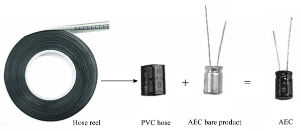
Fig. 1 Aluminum electrolytic capacitor and PVC hose
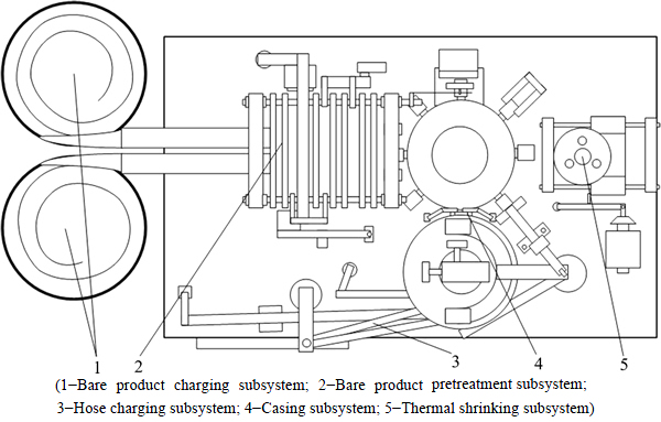
Fig. 2 Top view of aluminum electrolytic capacitor casing machine
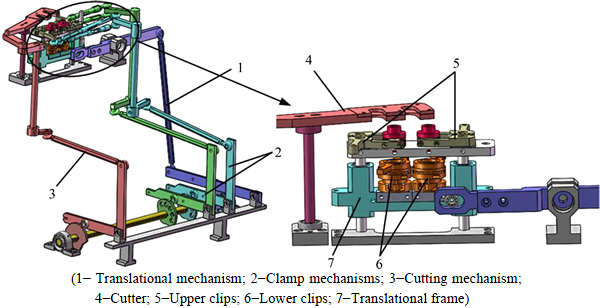
Fig. 3 3D model diagram of hose charging subsystem
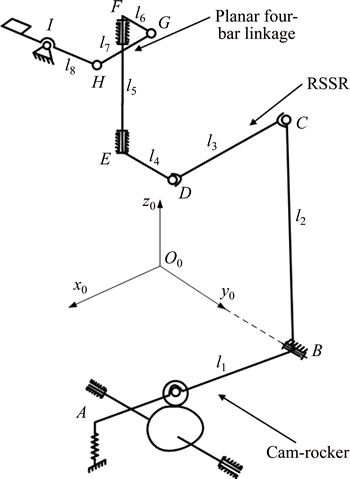
Fig. 4 Schematic of hose cutting mechanism
3.1 KED model of cam-roller substructure
For the cam-roller substructure, the LPM is used and the effects of prime mover and transmissions on the input motion of the camshaft are neglected. The schematic of the KED model is shown in Fig. 4. The cam is simplified as a lumped mass and a lumped moment of inertia, the roller is simplified as a lumped mass. The bending in x and y direction and the torsional vibration of the camshaft are considered in the model.
With reference to Fig. 5, the dynamic equations of the cam-roller substructures are expressed as follows:
 (1)
(1)
where m1 and m2 are lumped mass of the cam and roller; x1 and x2 are the horizontal elastic displacements of the cam and roller; y1 and y2 are the vertical elastic displacements of the cam and roller;��d and �� are the input angular displacement and elastic angular displacement of the camshaft, respectively; Jz is lumped rotational inertia of the cam; kx and ky are bending stiffness of the camshaft, cx and cy are the corresponding damping coefficients; kz and cz are torsion stiffness and damping coefficient of the camshaft; kcx and kcy are projections of the contact stiffness; ccx and ccy are projections of the contact damping coefficient between the cam and roller; cf is the friction damping coefficient of the camshaft support bearing; Mc is the moment generated by the roller; Fx and Fy are the force generated by L-rocker, respectively.
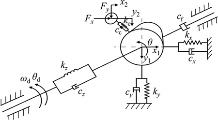
Fig. 5 KED model schematic of cam-roller substructur
The dynamic equations of the cam-roller substructure can be processed into matrix form as follows:
 (2)
(2)
3.2 Contact stiffness and damping of cam-roller substructure
The contact of the cam and roller can be regarded as two cylinders contact as shown in Fig. 5. The contact stiffness between the cam and the roller is expressed as
 (3)
(3)
where F is the positive pressure; h1 and h2 are depths of hertzian deformations on the roller and cam, respectively.
Assuming that the contact length of the cam and roller is B, the width of deformation is expressed as
 (4)
(4)
where ��1 and ��2 are material Poisson ratios of the cam and roller; E1 and E2 are material elastic modulus of the cam and roller; R1 and R2 are radius of cam and roller in the contact area, respectively.
The deformation depth of the contact area is written as
 (5)
(5)
The contact damping coefficient between the cam and roller is expressed as [3]
 (6)
(6)
where m1 and m2 are the related mass parameters; k12 is the contact stiffness; and �� is the damping ratio.
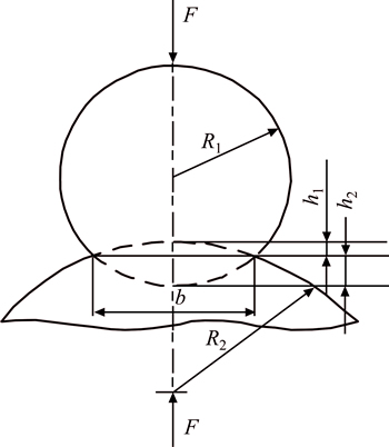
Fig. 6 Contact model of cam and roller
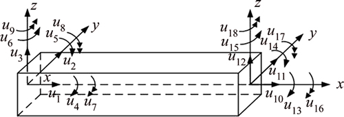
Fig. 7 Spatial beam element
4 KED model of linkage substructure
4.1 Spatial beam element
In this section, the spatial rectangular section beam shown in Fig. 7 is taken as an example to introduce the FEM. The node generalized coordinates are defined according to the elastic deformations of the beam element, u1-u3 and u10-u12 are transverse and axial displacements; u4-u6 and u13-u15 are angular displacements��u7-u9 and u16-u18 are the curvatures of torsional and bending deformations.
The elastic displacements of any point in the beam element can be calculated by the interpolation with the node elastic displacements, and expressed as
 (7)
(7)
where u=[u1, u2, ��, u18]T is the generalized coordinates vector of the spatial beam element; ��i(x) (i=1, 2, ��, 18) are the shape functions of the generalized coordinates; N1, N2, N3 and N4 are vectors of the shape functions; Wx(x,t) is the axial displacements; Wy(y,t) and Wz(y,t) are the transverse displacements; ��x(x,t), ��y(x,t) and ��z(x,t) are the angular displacements.
4.2 Dynamic model of spatial beam element
The Lagrange equation is written as follows:
 (8)
(8)
where Te is the kinetic energy of the beam element; Ve is the elastic energy of the beam element; fe is the vector of generalized external nodal forces.
The kinetic energy and elastic energy of the beam element are expressed as


 (9)
(9)


 (10)
(10)
where l is the length of the beam element; A is the cross-sectional area and �� is the material density; Ip is the cross sectional polar moment of inertia around x-axis; Iy and Iz are the cross sectional moment of inertia; Wax(x, t), Way(y, t), Waz(y, t), ��ay(x, t) and ��az(x, t) are absolute displacements and angular displacements of any point in the element; E and G are the elastic modulus and shear modulus.
Substituting Eqs. (9) and (10) into the Lagrange equation, the dynamic equations of the beam element are expressed as
 (11)
(11)
where me and ke are element mass matrix and element stiffness matrix, respectively; fe is the generalized force vector; is the rigid displacement array of the element.
The relationship between the coordinate vectors that depicts in the element coordinate system and the global coordinate system is written as follows:
u=RU (12)
where R is the coordinate transformation matrix between the element coordinate system and global coordinate system.
Substituting Eq. (12) into Eq. (11), the element dynamic equations are rewritten as follows:
 (13)
(13)
where m=RTmeR, k=RTkeR and f=RTfe.
4.3 KED model of linkage substructure
The FEM model of the linkage substructure is shown in Fig. 8. The linkage substructure is divided into seven elements. The links of the planar four-bar linkage and link DE are assumed to be rigid bodies since the stiffness is much larger than other links. To eliminate thefreedom of the linkage, revolute B is assumed to be a fixed end and three curvature coordinates are defined. The connecting rod CD of the spatial four-bar mechanism has a rotation isolated degree of freedom around its axis, and to eliminate the isolated degree of freedom, joint C is assumed to be a sphere-pin pair. Link EF only subjects torsion deformations and is modeled by a torsion element.
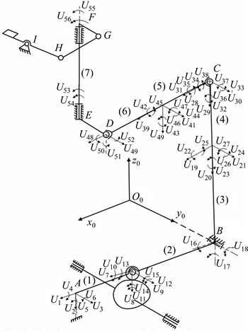
Fig. 8 Finite element model of linkage subsystem
For element i (i=1, 2, 3, ��, 7), the motion differential equations are expressed as follows:
 (14)
(14)
Link FG is chosen as the equivalent link of the planar four-bar linkage and the dynamic equation is expressed as follows:
 (15)
(15)
where �� is the angular displacement of link EF; Je is the equivalent moment of inertia of the planar four-bar linkage; and MF is the interaction moment between links EF and FG.
The dynamic equation of link DE is expressed as below:
 (16)
(16)
where ME is the interaction moment between link DE and link EF; JDE is the rotational inertia of link DE; and MD is the interaction moment between link CD and link DE.
The motion differential equations of the linkage substructure can be obtained by assembling the motion differential equations of the links.
 (17)
(17)
where ML and KL are mass matrix and stiffness matrix of the linkage substructure.
The damping matrix of the linkage substructure is assumed to be the form of linear combination of mass matrix and stiffness matrix as [10]
 (18)
(18)
where the coefficients of �� and �� in Eq.(18) are Rayleigh damping coefficients.
4.4 Motion differential equations of cutting mechanism
The motion differential equations of the hose cutting mechanism are obtained by assembling the motion differential equations of the cam-roller and the linkage substructure:
 (19)
(19)
where x=[x1 y1 �� U1 U2��U47 U50��U56]T, M, C and K are mass matrix, damping matrix and stiffness matrix of the cutting mechanism, respectively; F is the generalized force vector of the cutting mechanism.
5 Numerical simulation
5.1 Elastic deformation
The coefficient matrixes of the KED equations of the hose cutting mechanism (M, C, K) are functions of the mechanism position, and it is hard to get the analytic solutions. To solve the dynamic equations, the ��instantaneous structure hypothesis�� [11] is given. In the hypothesis, the period of motion is discrete to many small time units and the coefficient matrixes of the unit can be regarded as constant. The equations become ordinary differential equations and can be solved by numerical methods. Considering the stability, precision and computing speed, the Newmark method [12] is adopted to solve the equations.
Cam-rocker is the motion input part of the hose cutting mechanism, cycloid motion is selected as the motion law of the rocker and the normalized kinematic parameters of the rocker are shown in Fig. 9.
The elastic angular displacement U55 and the angular error of the cutter (link HI) under different camshaft rotational speed are shown in Fig. 10.Figures 10(a) and (c) depict the elastic angular displacement of link EF (U55). Figures 10(b) and (d) show the angle error of the cutter. It can be found that the rotational speed of the camshaft has great effects on elastic displacement of the cutting mechanism. The maximum elastic angular displacement of link EF (U55) increases from 0.1�� to 0.47�� with the rotational speed increasign from 100 to 200 r/min. In addition, the fluctuation trends of the elastic displacement are similarto the pseudo angular acceleration of the cam-rocker, indicating that the motion law of the cam-rocker also has important effects on the elastic displacements.
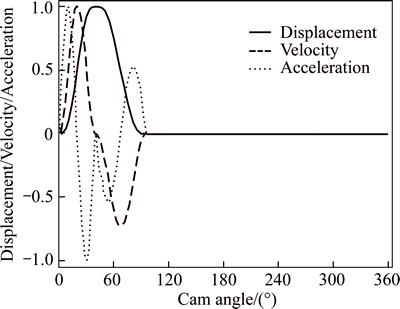
Fig. 9 Normalized kinematic parameters of rocker
5.2 Analysis of dynamic stress
Operating stress is an important factor which must be considered during structural designing of the mechanism. Excessive dynamic stress will lead to low reliability and fatigue failure. The dynamic stress of the links is investigated in this section on the basis of section 5.1. The normal stress and shear stress of any point in the spatial beam element can be expressed as
 (20)
(20)
where ��1(x, t), ��2(x, t) and ��3(x, t) are axial tension and compression stress, bending stress of y-axis and bending stress of z-axis, respectively; ��(x, t) is the torsion shear stress; yp and zp are position coordinates of any point in the beam section.
And


The links of the mechanism subject combine deformation of tension, torsion and bending. The equivalent stress defined by the fourth strength theory is written as
 (21)
(21)
The normal stress, shear stress and equivalent stress of any point in the element can be calculated based on Eqs. (20) and (21). And the maximum stress can be obtained through comparing the stress at the stationary points with the node stress. Take element (5) and torsional element (7) as examples, the maximum normal stress and shear stress are shown in Fig. 11 when the
camshaft rotational speed is 200 r/min. Figures 11(a) and (b) depict the maximum normal stress and shear stress of element (5). Figure 11(c) represents the maximum shear stress of element (7). As shown in the figures, it produces great fluctuations of the dynamic stress due to the compliance of the links. The strength of the links has a large surplus and the structure optimization should be done to make better use of the link strength.
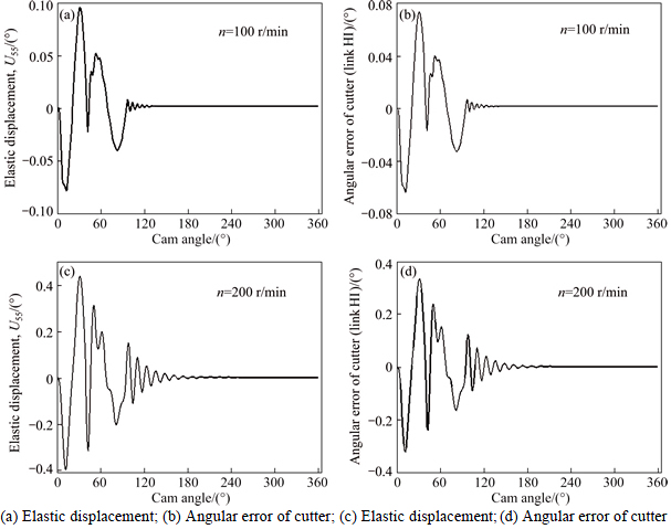
Fig. 10 Elastic angular displacement and angular error:
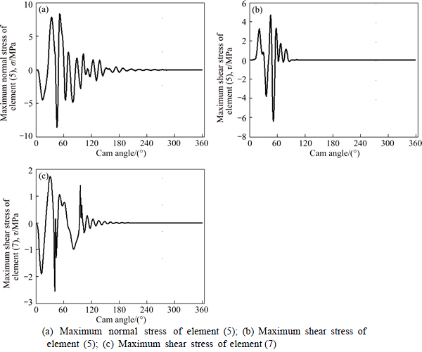
Fig. 11 Element maximum stress of linkage:
6 Conclusions
1) The KED model of the hose cutting mechanism of an AEC casing machine is established with a substructuring method.
2) The dynamic responses and the dynamic stress of the cutting mechanism are analyzed based on the model. The rotate speed of the camshaft and the compliance of the links have significant effects on the dynamic responses.
3) The KED model provides theoretical basis for structure optimization and vibration control of the mechanism which needs to be done in the near future.
References
[1] ZHANG Ce. Machinery dynamics [M]. Beijing, China: Higher Education Press, 2008: 199-291. (in Chinese).
[2] GATTI G, MUNDO D. On the direct control of follower vibrations in cam�Cfollower mechanisms [J]. Mechanism and Machine Theory, 2010, 45: 23-35.
[3] GUO Jie, ZHANG Win-ping, ZOU De-quan. Investigation of dynamic characteristics of a valve train system [J]. Mechanism and Machine Theory, 2011, 46(12):1950-1969.
[4] GUO Jie, ZHANG Win-ping, ZHANG Xin-yu, CAO Yi-peng. Dynamic and exciting analysis with modal characteristics for valve train using a flexible model [J]. Mechanism and Machine Theory, 2014, 78(16): 158-176.
[5] ERDMAN A G, SANDOR G N, OAKBERG R G. A general method for kineto-elastodynamic analysis and synthesis of mechanisms [J]. Journal of Manufacturing Science and Engineering, 1972, 94(4): 1193-1205.
[6] IMAM I, SANDOR G N, KRAMER S N. Deflection and stress analysis in high speed planar mechanisms with elastic links [J]. Journal of Manufacturing Science and Engineering, 1973, 95(2): 541-548.
[7] YU Yue-qing, SMITH M R. The effect of cross-sectional parameters on the dynamics of elastic mechanisms [J]. Mechanism and Machine Theory, 1996, 31(7): 947-955.
[8] CAI Gan-wei, CHANG Ping-ping, MA Cun-zhi, WANG Ru-gui, LI Zhao-jun. Dynamic analytic model of mechanism with links fabricated from symmetric laminates [J]. Journal of Central South University of Technology, 2006, 13(6): 624-630.
[9] DAI Cheng, XIA Bi-zhong, OUYANG Zhong-dong, LIU Yi-ran. Structure and development trend of the typical aluminum electrolytic capacitor casing machine [J]. Applied Mechanics and Materials, 2013, 341-342, 360-364.
[10] LIU Shan-zeng, YU Yue-qing, ZHU Zhen-cai, SU Liying, LIU Qing-bo. Dynamic modeling and analysis of 3-RRS parallel manipulator with flexible links [J]. Journal of Central South University of Technology, 2010, 17(2): 323-331.
[11] STAMPS F R, BAGCI C. Dynamics of planar, elastic, high-speed mechanisms considering three-dimensional offset geometry: analytical and experimental investigations [J]. Journal of Mechanisms Transmissions and Automation in Design, 1983, 105(3): 498-510.
[12] ZHANG Wu, CHEN Jian. Calculating displacement for automotive engine mounting system based on newmark [J]. Journal of University of Science and Technology of China, 2011, 41(12): 59-63.
(Edited by FANG Jing-hua)
Cite this article as:
XIA Biz-hong, REN Shi-yuan, LIU Xin-cheng, XU Chao. Kineto-elastodynamic analysis of hose cutting mechanism of an aluminum electrolytic capacitor casing machine [J]. Journal of Central South University, 2017, 24(4): 1217-1224.
DOI:https://dx.doi.org/10.1007/s11771-017-3525-6Received date: 2015-07-08; Accepted date: 2016-07-13
Corresponding author: REN Shi-yuan; Tel: +86-15989377646; E-mail: rsy13@mails.tsinghua.edu.cn
Abstract: The kineto-elastodynamic (KED) model of a hose cutting mechanism used in the aluminum electrolytic capacitor (AEC) casing machine is developed to investigate the dynamic characteristics. According to the composition characteristics, the cutting mechanism is divided into cam-roller and linkage two substructures. And the dynamic models of the two substructures are established using the lumped parameter method and finite element method (FEM), respectively. In the model, the compliances of the camshaft and the links are taken into consideration. The elastic displacement of the links, angular error of the cutter and the dynamic stress of the links are analyzed based on the KED model. The results provide important information for structure optimization and vibration control of the mechanism.
