

Bonding properties of interface in
Fe/Al clad tube prepared by explosive welding
SUN Xian-jun, TAO Jie, GUO Xun-zhong
College of Materials Science and Technology, Nanjing University of
Aeronautics and Astronautics, Nanjing 210016, China
Received 26 October 2010; accepted 11 April 2011
Abstract:
A Fe/Al clad tube was prepared by explosive welding. Then the bonding characteristic of the interface was investigated by compression, flattening and compression-shear test. The test results exhibit that the clad tubes possessing good bonding interface have higher shear strength than that of pure aluminum and can bear both axial and radial deformation. The original interface between aluminum layer and ferrite layer was observed by scanning electron microscopy (SEM). The results show that the clad tubes with good bonding properties possess the interface in wave and straight shape. The Fe/Al clad tube was used to manufacture the T-shape by hydro-bulging. It is found that the good-bonding interface of the Fe/Al clad tube plays a dominant role in the formation of the T-shape.
Key words:
Fe/Al clad tube; bonding property; interface; plastic deformation; T-shape; hydro-bulging;
1 Introduction
The ever-expanded uses of bimetallic transition joints in varied areas, such as heat transfer, chemical and atomic plant, ultra-high vacuum and cryogenic systems, result in an eager demand for improved corrosive resistance at different temperatures [1-3]. The pipe joints, as the important members of the conveying system, play a vital role in improving the flexibility, stability and safety of the system. They are traditionally manufactured by deformation from tubes. The preparation of bimetallic tubes can be achieved by many methods, such as spin-bonding [4], extrusion [5], diffusion welding [6-7], and explosive welding [8]. The joining of aluminum to stainless steel has been reported by these methods. The brittle intermetallic compounds in Al/stainless steel joint were produced with size in the range of few nanometers to a few hundred microns [9] at the interface by these technologies. The thinner the intermetallic phase, the better the bonding strength [10]. WANG et al [11] found that it was necessary to control the parameters of explosive welding for reducing compound of Al-Fe as far as possible. It was also detected that there is Al-Fe compound formed on the end of explosion when using low-energy explosives [12].
Explosive welding is accomplished by the exhaustive deformation owing to high pressure and high temperature created at the collision place. As a cold forming method, it keeps the bonded metals their pre-bond properties [13-14]. However, it is hard to find the investigations on the Fe/Al clad tube manufactured by explosive welding. In order to increase the corrosion resistance of the pipes, which need high strength and can bear high temperature as well as strong corrosion liquid, the Fe/Al clad tubes were manufactured by interior explosion process in this work. The mechanical tests, microscopic observation and the deformation of the clad tube were performed using the good-bonding and bad-bonding clad tube respectively. Finally, a T-shape was prepared successfully from clad tube.
2 Experimental
2.1 Materials
The pure ferrite (DT4) tube with the dimensions of d18.6 mm��350 mm��2.3 mm was used as the base tube, while the pure aluminium (1060) tube with the dimensions of d18 mm��400 mm��1 mm was employed as the cladding tube. The chemical composition of the base tube in mass fraction (%) was: C 0.006, Si 0.03, Mn 0.21, P 0.013, S 0.006, Cr 0.010, Ni 0.001, Cu 0.010, Al 0.068 and the balance Fe. Besides, the chemical composition in mass fraction (%) of the cladding tube was: Fe 0.35, Mn 0.03, Mg 0.03, Si 0.25, Sn 0.05, Ti 0.03, Cu 0.05 and the balance Al. The mixed powder of emulsion explosive, salt and some other components were used for the interior explosive process. The interior explosion process was conducted to joint the two dissimilar tubes. Pieces of copper sheets were inserted in the gap to keep it constant [15].
2.2 Interior explosion process
The interior explosion process was conducted to joint the two dissimilar tubes. Before welding, the explosive in powder form was placed in the cladding tube firstly. Then the cladding tube was placed inside the base tube separating by a distance with a surrounding metal mould. Finally, the detonator was placed at one end of the cladding tube.
The detonator was detonated by a small booster charge. Simultaneously, the expansion of the gaseous detonation products accelerated the cladding tube and made it get across the gap between the tubes. The cladding tube collided with the base tube at relatively high velocity then. On collision, a jet of both metals was ejected from the two tubes. This jet made the metals amenable to bonding by scouring and cleaning the surfaces of the tubes. The schematic diagram of arrangement and interior explosive process are shown in Fig.1 and Fig. 2, respectively.
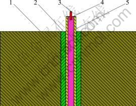
Fig. 1 Schematic diagram of arrangement: 1��Mould; 2��Ferrite tube; 3��Detonator; 4��Explosive; 5��Aluminium tube
2.3 Tests for bonding properties
The compression test, flattening test and compression-shear test were conducted to evaluate the bonding properties of the clad tube. The samples were cut from the middle of the Fe/Al clad tube in circular ring shape. The heights of the samples for compression, flattening and compression-shear tests were 27 mm, 18 mm and 1 mm, respectively.
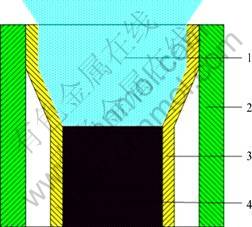
Fig. 2 Schematic diagram of interior explosive welding: 1��Gaseous detonation products; 2��Ferrite tube; 3��Aluminium tube; 4��Explosive
All the tests were performed on the CMT 5105 electronic universal testing machine with compression test under axial load, flattening test under radial load and compression-shear test under shear stress. Figure 3 shows the schematic diagram of the compression-shear test and the mould. The increasing loading was restricted to the aluminium layer only by the squeeze head in this test. The test stopped after the stroke of the squeeze head exceeded 1 mm. Meanwhile, the peak value of the loading was obtained in the machine. The shear strength of the joint can be calculated by Eq. (1), where �� is the shear strength; F is peak value of the force loading on the aluminium layer; A is the fracture area in the interface; d is the section diameter of fracture area in the interface; h is the height of the sample; and �� is the ratio of circumference.
![]() (1)
(1)
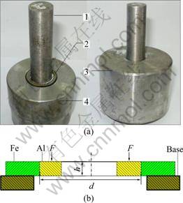
Fig. 3 Schematic diagram of compression-shear test (a) and details of sample (b): 1��Squeeze head; 2��Sample; 3��Location sleeve; 4��Base
2.4 Microscopic observation
All samples were ground and polished to 1 ��m- finish. The interfaces between the layers of the Fe/Al clad tube were detected using the scanning electron microscope (SEM, Quanta 2000).
2.5 Hydroforming process
The schematic diagram of hydroforming process for tee extrusion is exhibited in Fig. 4. The inner cavity was composed of a pair of split dies. A couple of hydraulic cylinders were installed horizontally in both sides of the work piece. Firstly, the tube blank was placed in the lower half of a split die. Then the die was closed by the upper hydraulic press. Simultaneously both end sides of the tube were sealed by horizontal cylinders and the hydraulic liquid was injected into the tube blank. When the pressure was sufficient to initiate the bulging, both ends of the tube were pushed inwards and then horizontal displacement acted on the ends of the tube to avoid excessive thinning. The tube wall was made to flow into the branch cavity of the upper die, maintaining intimate contact with the cavity profile because of the internal hydraulic pressure.
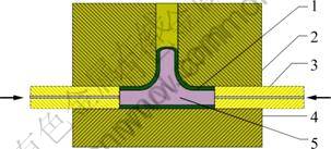
Fig. 4 Schematic diagram of hydroforming process for tee extrusion: 1��Tube blank; 2��Upper die; 3��Hydraulic cylinder; 4��Lower die; 5��Liquid
3 Results and discussion
3.1 Compression tests
The samples were compressed by 35% in compression test. As shown in Fig. 5(a), the aluminium layer bulges during the deformation process. This indicates that the aluminium layer separates from the ferrite layer due to the weak interface, showing the poor bonding property. But no bulging is detected in the sample as shown in Fig. 5(b). In order to observe the interface better, the sample is cut in half. No crack is detected according to the view of the corresponded interface. The clad tube presents good-bonding property, bearing large and axial deformation.
3.2 Flattening tests
Figure 6 shows the views of samples after flattening test. The interface of clad tube after flattening test has a similar deformation behavior to that after compression test. Therefore, it is claimed that the good-bonding Fe/Al clad tube can bear large and radial deformation.
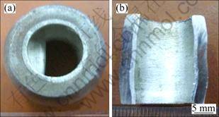
Fig. 5 Views of samples after compression test: (a) Bad-bonding sample; (b) Good-bonding sample
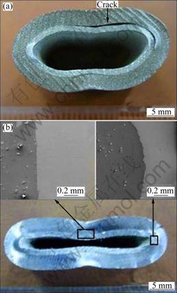
Fig. 6 Views of samples after flattening test: (a) Bad-bonding sample; (b) Good-bonding sample
3.3 Compression-shear tests
The views of samples after compression-shear test are depicted in Fig. 7. The aluminium layer separated from the ferrite layer in part of the interface because the shear strength of the bad-bonding interface is lower than that of the aluminium. However, the fracture was found in the aluminium layer of good-bonding sample only (see Fig. 7(b)). This implies that the shear strength of the good-bonding interface is higher than that of the aluminium layer. The aluminium and ferrite layers are bonded together closely.
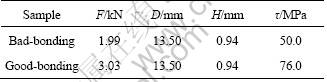
Table 1 shows the compression-shear test results of the bad-bonding and good-bonding samples. It is clearly that the value of the bad-bonding sample is about one third of that of the good-bonding sample. The gap between the values of shear strength contributes to the fracture place happening at the interface. The test result of the shear-strength for good-bonding sample is 76.0 MPa. For the fracture happened in aluminium layer only, it can be deduced that the shear-strength of the good-bonding interface is higher than 76.0 MPa.
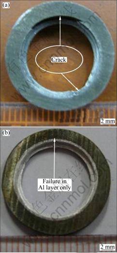
Fig. 7 Views of samples after compression-shear test: (a) Bad- bonding sample; (b) Good-bonding sample
Table 1 Results of compression-shear test
3.4 Micrographs of interface
The micrographs of the interface shown in Fig. 8 correspond to tube with good-bonding properties. Position A is in the initiation, while positions B and C are in the middle and the end of the tube respectively. The differences could be witnessed easily from the interfaces of the parts following the detonation direction. In the initiation part, the Fe/Al clad tube bonds together directly, having little transition layer. In the middle of tube, it shows the wave shape at the interface which reveals the good-bonding properties depicted above. And in the end, it exhibits more transition layers in the interface, showing that the Fe and Al layers joint together in melting layer. These differences are related to the increasing detonation energy from the initiation to the end that will be not enough for the binding when it is too low and lead to severe fusion at the interface which is bad to the deformation of clad tube when it is over high. It is also concluded by the analysis of differences in the clad tube that the explosive welding window of Fe/Al clad tube is limited. The Fe and Al element distribution of interface in the middle of tube is shown in Fig. 9. It is detected that the thickness of the layer is less than 3 ��m. And from the distribution of Al and Fe which varies gradually, it could be speculated that there is no intermetallic compound generated at the interface after explosive welding.
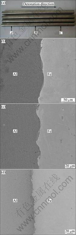
Fig. 8 Secondary electron images of interface with good- bonding properties: (a) Sampling positions; (b) Interface at position A; (c) Interface at position B; (d) Interface at position C
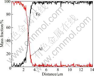
Fig. 9 Element distribution of interface in the middle of tube
The micrographs of the interface given in Fig. 10 correspond to poor-bonding properties. The two interfaces displayed in the axial cross section of the clad tube are not symmetrical. One exhibits a clear separation, the other bonds well but has a thicker transition layer. It is speculated that the asymmetrical gap between the base and cladding tubes is probably a major cause of the asymmetric interfaces. It is important to make sure the gap constant and suitable before performing explosive welding.
3.5 Fe/Al clad tube T-shape
Figure 11 provides the failure view of the clad tube T-shape after hydroforming process. The fracture occurs on the top of the T-shape with serious separation between the aluminium and the ferrite layer. The aluminium layer at the marked zone (see zone A shown in Fig. 11) fractures firstly due to the excessive thinning. Subsequently, the crack probably generates and propagates at the weak interface at zone A, and then the separation happens between the Al and Fe layers. With the excessive thinning of the wall, the fracture in Al layer will occur firstly because of the lower strength of Al than Fe, which makes the hydraulic liquid contact with the interface directly. As a result, much more separations will be generated between the two layers because the hydraulic pressure is too high for the shear strength of the interface. Finally, the single ferrite layer cracks when the thinning process is going on. This confirms that the weakness at the interface is harmful to the plastic deformation of the clad tube.
The Al and Fe layers deform concordantly from the observation of the excellent clad tube T-shape given in Fig.12, with no separation detected at the interface. Therefore, the Fe/Al clad tube is strong enough to be used to fabricate the clad tube T-shape.
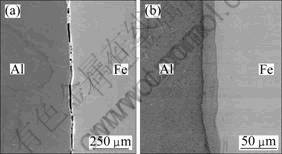
Fig. 10 Micrographs of interface with poor-bonding properties: (a) One interface; (b) The other interface
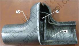
Fig. 11 View of failure after hydroforming process
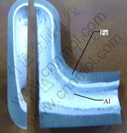
Fig. 12 Sectional view of excellent Fe/Al clad tube T-shape
4 Conclusions
1) The good-bonding Fe/Al clad tube was prepared successfully by interior explosive process. The clad tube possesses the good-bonding interface in wave shape with a shear strength of more than 76.0 MPa, thus could bear axial and radial deformation. The detonation energy increases gradually from the initiation to the end of the clad tube. The process window of explosive welding is so narrow that we should choose the process parameters carefully.
2) The Fe/Al clad tube possessing the asymmetric interfaces exhibits poor-bonding properties. It is found that the asymmetrical gap between the base and cladding tubes leads to the asymmetry of the interface.
3) The tube T-shape is manufactured successfully by hydroforming process using the Fe/Al clad tube with good bonding property, while the manufactured process is probably to fail using the tube possessing weak interface.
Acknowledgement
The authors are grateful to Professor LU Ming and doctor candidate Mr. LIU Peng of PLA University of Science and Technology for their assistance in preparing the Fe/Al clad tube by explosive welding.
References
[1] LI F, ZHENG J, XU P, XU M, ZHU G. Forming mechanism of double-layered tubes by internal hydraulic expansion [J]. International Journal of Pressure Vessels and Piping, 2004, 81: 625-633.
[2] TRICARICO L, SPINA R, SORGENTE D, BRANDIZZI M. Effects of heat treatments on mechanical properties of Fe/Al explosion-welded structural transition joints [J]. Materials and Design, 2009, 30: 2693-2700.
[3] TAVASSOLI A A F. Overview of advanced techniques for fabrication and testing of ITER multilayer plasma facing walls [J]. Fusion Engineering and Design, 1998, 39-40: 189-200.
[4] MOHEBBI M S, AKBARZADEH A. A novel spin-bonding process for manufacturing multilayered clad tubes [J]. Journal of Materials Processing Technology, 2010, 210: 510-517.
[5] LEE J S, SON H T, OH I H, KANG C S, YUN C H, LIM S C, KWON H C. Fabrication and characterization of Ti-Cu clad materials by indirect extrusion [J]. Journal of Materials Processing Technology, 2007, 187-188: 653-656.
[6] KUNDU S, CHATTERJEE S. Diffusion bonding between commercially pure titanium and micro-duplex stainless steel [J]. Materials Science and Engineering A, 2008, 480: 316-322.
[7] BHANUMURTHY K, FOTEDAR R K, JOYSON D, KALE G B, PAPPACHAN A L, GROVER A K, KRISHNAN J. Development of tubular transition joints of aluminium stainless steel by deformation diffusion bonding [J]. Materials Science and Technology, 2006, 22(3): 321-330.
[8] ACARER M, G?LEN? B, FINDIK F. Investigation of explosive welding parameters and their effects on microhardness and shear strength [J]. Materials and Design, 2003, 24: 659-664.
[9] YANG L, HOSODA N, SUGA T. TEM investigation of the stainless steel/aluminum interface created by the surface activated bonding method [J]. Nuclear Instruments and Methods in Physics Research Section B, 1997, 121: 519-523.
[10] HUANG Y, RIDLEY N, HUMPHREYS F J, CUI J Z. Diffusion bonding of superplastic 7075 aluminium alloy [J]. Materials Science and Engineering A, 1999, 266: 295-302.
[11] WANG Bao-yun, MA Dong-kang, LI Zheng-xian. Microanalysis of combine interfaces of Al/stainless steel thin walled clad tube by explosive welding [J]. Rare Metals Letters, 2006, 25(2): 26-30.
[12] WANG Bao-yun, MA Dong-kang, LI Zheng-xian, DU Ji-hong. Research of producing Al/stainless steel thin walled clad tube by interior explosive welding [J]. Welding and Joining, 2005, 5: 54-57.
[13] AKBARI MOUSAVI S A A, FARHADI SARTANGI P. Experimental investigation of explosive welding of cp-titanium/AISI 304 stainless steel [J]. Materials and Design, 2009, 30: 459-468.
[14] DURGUTLU A, G?LEN? B, FINDIK F. Examination of copper/stainless steel joints formed by explosive welding [J]. Materials and Design, 2005, 26: 497-507.
[15] WANG Yao-hua, LU Ming, ZHOU Chun-hua, GU Yue-bing, LIU Peng, DAI Ru-xun, LIU Bin, LONG Yuan, JIN Guang-qian, LIU Ying. Explosive welding process of composite tube used in nuclear system: China, ZL200910025068.4[P]. 2009-02-16.
��/����ը����˫�����ܽ���Ľ������
���Կ�, �� ��, ��ѵ��
�Ͼ����պ����ѧ ���Ͽ�ѧ�뼼��ѧԺ���Ͼ� 210016
ժ Ҫ�����ñ�ը���ӷ��Ʊ�Fe/Al˫�������Ϲܣ�Ϊ�������Ϲܽ���Ľ�����ܽ�����ѹ����ѹ�⼰ѹ��ʵ�顣ʵ�������������Ϲܽ�����ã������ǿ�ȴ��ڴ�����Ŀ���ǿ�ȣ������ܹ���������;�����Ρ�����ɨ����������۲���ԭʼ������ò�����Խ��������������õĸ��Ϲܽ���ʲ�״��ֱ��״������Һѹ���ι�����Fe/Al˫�������Ϲ��Ʊ������Ϲ�����ͨ���������õĽ����϶���/��˫�����ܵ����Գ��;�����Ҫ���á�
�ؼ��ʣ���/��˫�����ܣ����ǿ�ȣ����棻���Ա��Σ�����ͨ��Һѹ����
(Edited by YANG Hua)
Foundation item: Project (BA2006067) supported by Achievement Transitional Foundation of Jiangsu Province, China
Corresponding author: TAO Jie; Tel: +86-13347800587; E-mail: taojie@nuaa.edu.cn
DOI: 10.1016/S1003-6326(11)60991-6
