

Nonlinear ultrasonic characterizing online fatigue damage and in situ microscopic observation
WU Bin1, YAN Bing-sheng1, 2, HE Cun-fu1
1. College of Mechanical Engineering and Applied Electronics Technology, Beijing University of Technology,Beijing 100124, China;
2. School of Mechanical and Electrical Engineering, Henan University of Technology, Zhengzhou 450007, China
Received 24 December 2010; accepted 16 May 2011
Abstract:
A robust experimental procedure was developed, by which the evolution of fatigue damage in AZ31 magnesium alloy was tracked online with the ultrasonic nonlinearity parameter ��. �� values of three sets of samples under different stress levels were measured. Microstructures of specimens at different fatigue stages were observed in situ by optical microscopy. The experimental results show that there is a significant increase in �� linked to the accumulation of persistent slip bands (PSBs) and micro-cracks at the early stages of fatigue life and reaches the maximum, about 55% of fatigue life. Ultrasonic attenuation coefficient increases with the expanding of micro-cracks and leads to �� decrease slightly after 55% of fatigue life. The variation of �� with fatigue cycles is in good agreement with the growth of PSBs and micro-cracks. In addition, it has no significant effect on the experimental results for the changes of low- and high-cycle fatigue and the fatigue mode with tension-tension and tension-compression.
Key words:
nonlinear ultrasonic; AZ31 magnesium alloy; fatigue damage; persistent slip bands;
1 Introduction
Fatigue life of metal parts can be generally divided into three stages: material degradation at early stage including the generation of dislocation group and formation of persistent slip bands (PSBs), initiation and accumulation of micro-cracks, and the terminal rupture failure. To well-designed mechanical components, the first and the second stages spend 80%-90% of the fatigue life [1]. Therefore, it is necessary to develop an effective method to nondestructively monitor the early fatigue damage of metallic materials.
Ultrasonic nondestructive testing (NDT) technique can measure and evaluate the third stage of fatigue life by linear physical parameters such as sound speed and attenuation [2]. These physical parameters, however, are not sensitive enough to detecting the accumulation of dislocations and PSBs in the early stages of fatigue life [3]. In recent years, nonlinear ultrasonic theory and experimental results show that the early fatigue damage in metals is closely related to the nonlinear effects of ultrasonic waves [4-8]. Nonlinear ultrasonic studies are based on the generation of higher harmonics of the fundamental frequency due to distortion of monochromatic sinusoidal ultrasonic waves as they propagate through metals with the accumulation of dislocations. Therefore, nonlinear ultrasonic technique can be used to quantify the presence and the density of micro-defects in metallic materials, and then it can measure fatigue damage in a quantitative fashion by this way.
Many investigators have applied nonlinear ultrasonic techniques to assessing fatigue damage under laboratory conditions. NAGY [3] illustrated that the nonlinear acoustic parameters are earlier and more sensitive indicators of fatigue damage than their linear counterparts. YOST and CANTRELL [9] experimentally observed the changes of the acoustic nonlinearity parameters and attributed the changes to the effects of fatigue-induced dislocations. In order to confirm the correlation between the nonlinear acoustic effect and the material degradation, JHANG and KIM [10] offline measured the nonlinearity parameters of several specimens with different degrees of degradation, but the results had greater dispersion. JAYA RAO et al [11] qualitatively researched the relationship between nonlinearity parameters and fatigue plastic strain of aluminum alloy, and observed the changes of dislocation pits density.
There are very few examples of its successful application to monitor fatigue damage in spite of the recognized potential of nonlinear ultrasonics. Few literatures reported online detected fatigue damage of magnesium alloy by using nonlinear ultrasonic waves. Since magnesium alloy components have poor fatigue performance issues in complex working conditions, this research develops a robust experimental procedure and achieves online measurement of nonlinearity parameters. Using this system, ultrasonic nonlinearity parameters of three sets of AZ31 magnesium alloy specimens under different loading stresses are measured. An experimental phenomenon is verified by microscopic observation of magnesium alloy specimens in situ.
2 Acoustic nonlinearity parameter �� and nonlinear acoustic effect in fatigued material
Ultrasonic nonlinear effects are the cause of the generation of higher harmonics in an acoustic wave propagating through a structural material due to material nonlinearity. Ultrasonic nonlinearity is usually characterized by a nonlinearity parameter ��, by which the amount is quantified that an ultrasonic wave is distorted as it travels through the specimen. Considering the one-dimensional problem of longitudinal wave propagation through a nonlinear solid, CANTRELL [12], BREAZEALE and JACOB [13] established the nonlinear wave equation for displacement ![]() as follows:
as follows:
![]() (1)
(1)
where ��0 is the density of medium; u is the displacement; ![]() is the propagation distance of sound wave;
is the propagation distance of sound wave;![]() is the second-order elastic constant; and
is the second-order elastic constant; and![]() is the third-order elastic constant.
is the third-order elastic constant.
Acoustic nonlinear parameter![]() is defined as [12]
is defined as [12]
![]() (2)
(2)
To obtain a solution of Eq. (1), a perturbation theory is applied. The displacement u is assumed as
![]() (3)
(3)
where u(0) represents the initially excited wave and u(1) represents the first-order perturbation solution. u(0) is considered a single frequency sinusoidal waveform:
![]() (4)
(4)
where k is the wave-number, then the perturbation solution can be obtained as follows:
![]()
![]() (5)
(5)
Due to the nonlinear material properties, it can be seen from Eq. (5) that an initially single frequency sinusoidal wave generates higher harmonics![]() in a nonlinear medium. The amplitudes of the fundamental and the second-harmonic are expressed as
in a nonlinear medium. The amplitudes of the fundamental and the second-harmonic are expressed as![]() .
.
![]() (6)
(6)
Eq. (7) is obtained by rearranging Eq. (6).
![]() (7)
(7)
It is observed from Eq. (7) that, by knowing the acoustic velocity![]() and the fundamental frequency
and the fundamental frequency![]() , the acoustic nonlinearity parameter can be calculated by measuring the absolute displacement amplitudes of the fundamental
, the acoustic nonlinearity parameter can be calculated by measuring the absolute displacement amplitudes of the fundamental![]() and the second harmonic
and the second harmonic![]() after they have propagated a distance
after they have propagated a distance![]() through the sample.
through the sample.
In general, a solid medium is nonlinear. Acoustic nonlinearity of metal material origins mainly from two aspects: 1) the anharmonicity of lattice itself; and 2) the dislocations, PSBs and micro-cracks in material internal. The acoustic nonlinearity from micro-defects is higher than the intrinsic nonlinearity of the intact material [3, 14]. As the result of the cycling stresses, fatigue of metallic material promotes the changes of dislocation and PSBs, etc. The changes in the micro-structural level due to damage accumulation introduce changes in the material response, and in particular lead to changes of ultrasonic nonlinearity parameters �� [15-16]. Therefore, the damage accumulated during the fatigue process can be estimated by measuring ��.
3 Experimental
Figure 1 shows a schematic diagram of the proposed nonlinear ultrasonic measurement system. The system includes function generator (33220A), power amplifier (AG1016), materials testing system (MTS810), high-energy low-pass filter, attenuator, sensor, oscilloscope, computers, online test specimens and fixture.
Amplitudes of the fundamental and second harmonic wave were measured by transmission method in this experimental system. A tone burst signal at 5 MHz from a function generator is fed into a high-power amplifier during the specimen loading process. The amplified high-voltage signal passes through a high-energy low-pass filter to filter high frequency interference signal which is from power amplifier RF gate. Commercial narrow-band PZT-base piezoelectric transducers, with center frequencies of 5 MHz and 10 MHz, are used as a transmitter and a receiver, respectively. The two transducers are longitudinal wave right angle probe, and the effective diameter is 12 mm. The transducers are coupled to the specimen with lithium grease. A special fixture is designed to keep both the transmitting and receiving transducers on the same centerline axis. The received signals are recorded and averaged 512 times with oscilloscope, and transferred to a computer for further signal processing. Then, the fundamental and the second harmonic signal amplitudes are measured after acquiring signals for FFT.
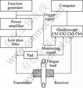
Fig. 1 Schematic diagram of experimental setup
In addition, one of the signals from the filter passes through pad to attenuate the signal amplitude, and then is sent to oscilloscopes as a monitoring signal to control the amplitude of an excitation signal.
The specimen for fatigue testing is shown in Fig. 2. The material is AZ31 magnesium alloy, whose yielding stress is 199 MPa, elastic modulus is 46 GPa, Poisson ratio is 0.27, density is 1770 kg/m3, and speed of sound is 5710 m/s. The specimen has an arc shape to create a region of higher stress at its center. Note that the surface finishes on all specimens in this study are as-machined.

Fig. 2 Dimensions of specimen (mm)
Figure 3(a) shows an example of a transmitted and received time domain signal. In order to ensure one-dimensional wave propagation in a single direction, the exact number of cycles of the tone burst is selected as the maximum number of cycles that can fit within the thickness of the specimen. This eliminates any possible spurious higher harmonics generated by the interference of the incident and reflected wavefronts, as well as the effects of boundary conditions. In this work, the number of cycles is ascertained as 7. The solid curve is transmitted signals and corresponds to the left coordinate in Fig. 3(a), and the dotted curve is received signals and corresponds to the right coordinate in Fig. 3(a).
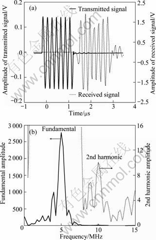
Fig. 3 Experimental signals: (a) Example of transmitted and received time domain signals; (b) Fundamental and the 2nd harmonic amplitudes
Figure 3(b) shows the Fourier spectra of received signals, including fundamental and second harmonic amplitudes. Compared with the fundamental amplitude, the second harmonic amplitude is very small. Figure 3(b) shows the second harmonic clearly in the fundamental wave figure. The solid curve at 5 MHz is the fundamental amplitude and corresponds to the left coordinate in Fig. 3(b), while the dotted curve at 10 MHz is the second harmonic amplitude and corresponds to the right coordinate in Fig. 3(b).
4 Results and discussion
4.1 Second harmonic amplitude versus amplitude of fundamental squared
According to Eq. (7), the second harmonic amplitude is proportional to the amplitude of fundamental squared when the excitation signal frequency and ultrasonic propagation distance remain constants, thus the reliability of the experimental system can be tested.
Using the above experimental methods and setup, the amplitudes of fundamental and the second harmonic are measured on the same specimen as a function of increasing input voltage amplitude. In this case, the driving voltage level varies from 240 V to 350 V, increased by 10 V per time. Figure 4 shows the best fit curve of the second harmonic amplitude versus the amplitude of the fundamental squared for increasing driving voltages.
The best fit equation is
![]()
From Eq. (7), the linear correlation coefficient is r=0.999 6, which means![]() and
and![]() are highly linear correlation. Therefore, the ultrasonic nonlinearity parameter �� keeps a constant for different input voltages within a certain range.
are highly linear correlation. Therefore, the ultrasonic nonlinearity parameter �� keeps a constant for different input voltages within a certain range.
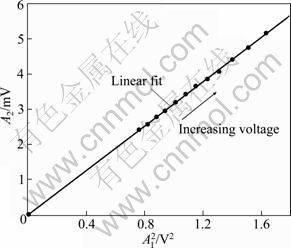
Fig. 4 Second harmonic amplitude versus amplitude of fundamental squared for increasing input voltage
4.2 Ultrasonic nonlinearity parameters versus fatigue life
The six specimens are evenly divided into three sets, including A, B and C. Specimens of A and B sets for the fatigue test are stretched and compressed periodically in MTS810. The frequency of cyclic loading is 10 Hz, and R=��min/��max=-1. In order to obtain the influence of different loading stresses on the experimental results, the specimens of the A set are loaded to a bigger stress, which level is �� 65% (�� 129 MPa) of the yield stress. The A1 and A2 specimens of the A set fail at 39000 and 87800 cycles. The specimens of the B set are loaded to a smaller stress, which level is �� 60% (�� 119 MPa) of the yield stress. The B1 and B2 specimens of the B set fail at 175000 and 218000 cycles.
The specimens of the C set for the fatigue test are stretched and stretched periodically in MTS810. The frequency of cyclic loading is 10 Hz, and R=��min/��max= 0.1. The loading stress is 18.9-189 MPa. The C1 and C2 specimens of the C set fail at 69986 and 81500 cycles.
Specimens and probes are fixed on MTS810 by a special fixture. Firstly, the nonlinearity parameter ��0 of an undamaged specimen is measured before any mechanical load is applied. Then the nonlinearity parameters �� are measured in an equal time interval when the specimen is fatigued. As a result, the measured ultrasonic nonlinearity parameters will be normalized for ��/��0. Fatigue life is normalized by fatigue cycle to the total number of cycles, where 100% means the total fatigue life [8].
Figure 5 shows the curves of the relationship between normalized ultrasonic nonlinearity parameters and fatigue life for fatigue specimens of the A, B and C sets. The thin solid lines are the curves from original data and the thick solid lines with small circles are the curves from an average of 10 adjacent original data. As can be seen from figures, the overall trends of curves are similar although the experimental results of each sample have some differences. So, these curves may imply the internal microstructure variation of a material. Every curves of all the above figures can be divided into two phases. In the first phase, there is a rapid increase in ��/��0 before about 55% of fatigue life, which demonstrates that these nonlinear ultrasonic measurements can be used to quantitatively characterize the damage state of this material in the early stages of fatigue life. In the second phase, ��/��0 begins to decrease and has greater volatility after about 55% of fatigue life.
Figure 6 shows a mean value in ��/��0 of the above six specimens at the same percentage of fatigue life. A mean value is taken in every 4% of fatigue life, and then these mean values are fitted. The best fit equation is
![]()
where N is percentage of fatigue life.
Experimental results show that the best fit curve between the nonlinearity parameter ��/��0 and fatigue life has the potential to serve as a master curve for life prediction based on nonlinear ultrasonic measurements.
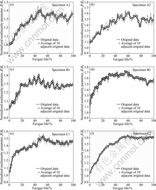
Fig. 5 Normalized ultrasonic nonlinearity parameter as function of fatigue life for fatigue specimens of A, B and C sets
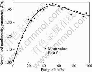
Fig. 6 Normalized ultrasonic nonlinearity parameter as function of fatigue life for average of six fatigue specimens
4.3 Discussion
Using online measurement, more data can be collected, the couplant need not be replaced during experiment and the impact of coupling transform in offline experiments is ruled out. Moreover, the experimental environment is closer to engineering practice. As can be seen from experimental results, the curve is more continuous and the dispersion is smaller than the offline result.
The experimental results of A, B and C sets have no apparent regular differences. Therefore, it has no significant effect on the experimental results for the changes of low- and high-cycle fatigue and the fatigue mode with tension-tension and tension-compression.
Although the six samples are from the same batch of material, there are still some individual differences of internal microstructure. These inherent differences lead to six curves which are not totally identical.
5 In situ microscopic observations
There are a lot of dislocations in real metal crystal, which have movement under the external force, and then lead to decrease of intensity of metallic materials. Metal crystal slip is essentially achieved by dislocation slip. The dislocations in AZ31 magnesium alloy will increase continuously with fatigue cycles increasing, while the dislocation slip will form a large number of PSBs. It is difficult to observe directly dislocations by optical microscope, but PSBs and micro-cracks can be observed.
5.1 Specimen preparation
In order to verify experimental results in micro-structure, PSBs and micro-cracks on the specimen surface are observed by KEYENCE VH-2500 optical digital microscope in situ. Figure 7 shows a typical corroded AZ31 magnesium alloy specimen for observing in optical microscope. Firstly, the stress concentration area on the specimen surface is grinded, polished, and corroded in turn. Then, the original morphology of a specimen surface is observed and saved as the selected viewing area is marked by a fine pin. Finally, the test specimens will be subjected to sinusoidal loading under tension-compression mode at a frequency of 10 Hz. The stress level is �� 65% (�� 129 MPa) of the yield stress and![]() . The marked position on specimen surface is observed in every 6000 cycles with microscope before fracture failure.
. The marked position on specimen surface is observed in every 6000 cycles with microscope before fracture failure.
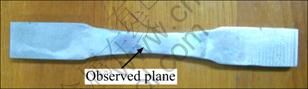
Fig. 7 Specimen corroded for microscopic observation
Corrosion solution used in the experiment is nitric acid (1%), oxalic acid (0.5%), acetic acid (0.5%) and water (98%) mixed solution. Corrosion time is 15 s. The observation plane is covered by cotton wool to ensure the surface clean in the process of fatigue loading. The specimen fails at 32000 cycles.
5.2 Observation and discussion
Figure 8 shows the image of surface microstructure for tested specimen at different stages of fatigue life. To ensure observation for the same area, the mark is pined, shown in Fig. 8 as black area. From Fig. 8, it can be seen that PSBs emerge and increase with the fatigue cycles increasing, as micro-crack also starts appearing and expanding. In order to quantify the changes of PSBs and micro-cracks, two fixed areas in every image of Fig.8 are chosen, such as oval area for the changes in the length of micro-crack, and the square area for the changes in the number of PSBs.
Figure 9 shows the changes of PSBs and micro-crack with fatigue life. Nonlinearity of metal materials mainly derived from the dislocations, PSBs, micro-cracks and other micro-defects [6]. It can be seen from Fig. 9, increase of PSBs induced by the fatigue cycles is the main factor for ultrasonic nonlinearity parameters increasing before about 40% of fatigue life. Micro-cracks sprout at about 40% of fatigue life. Accumulation of dislocations, PSBs and expansion of micro-cracks result in collaboratively the ultrasonic nonlinearity parameters to continuous increase, and then �� reaches the maximum at about 55% fatigue life. At about 60% of fatigue life, the dislocation density gets saturated and the micro-cracks expand to macro-cracks. Then, ultrasonic attenuation coefficient of materials increases with macro-cracks growing. Ultrasonic attenuation coefficient is proportional to the square of ultrasonic frequency. Therefore, the attenuation of the second-harmonic is greater than that of fundamental wave. The ultrasonic nonlinearity parameters will decrease with the macro-cracks increasing after about 60% of fatigue life.
In addition, there is an inherent randomness in the progression of fatigue damage during fatigue testing, which should manifest itself as a corresponding randomness in the resulting acoustic nonlinearity. The surface deformation associated with the increased plasticity makes it difficult to consistently couple the transducers to the specimen surface at the later stages of fatigue life. The opening and closing of crack will also lead to the fluctuation of the ultrasonic nonlinearity parameters.
Microscopic observations verify the nonlinear ultrasonic fatigue test experimental results, and explain why nonlinearity parameters decrease at the later stages of fatigue life. So, there is a certain relationship among ultrasonic nonlinearity parameters, fatigue life and internal microstructure of materials. Ultrasonic nonlinearity parameters can be used as quantitative indicators of prediction fatigue life of the AZ31 magnesium alloy.
6 Conclusions
1) A robust experimental procedure was developed to measure the ultrasonic nonlinearity parameters with PZT-base piezoelectric transducers. There is approximately linear relationship between the second-harmonic amplitude and the amplitude of the fundamental squared for increasing input voltage, and the experimental system is reliable.
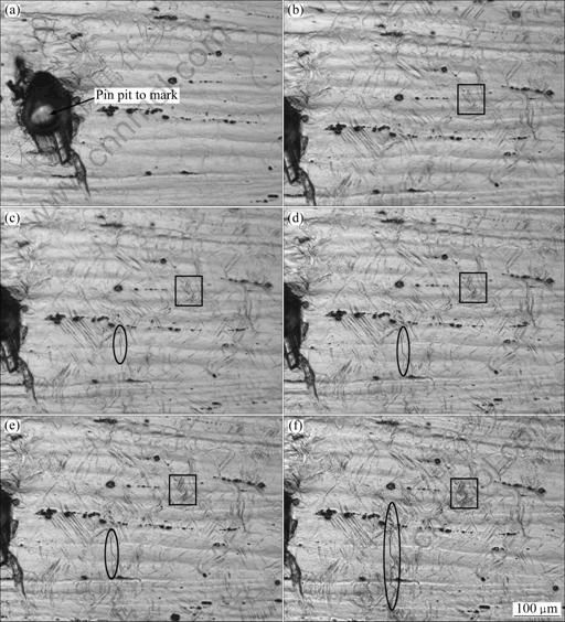
Fig. 8 Surface microstructures of tested specimen at different stages of fatigue life: (a) Original; (b) 19% of fatigue life; (c) 38% of fatigue life; (d) 56% of fatigue life; (e) 75% of fatigue life; (f) 94% of fatigue life
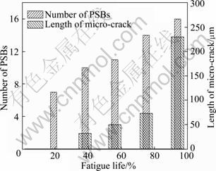
Fig. 9 Changes of PSBs and micro-crack with fatigue life
2) The relationship among the ultrasonic nonlinearity parameters, fatigue life and internal microstructure of AZ31 magnesium alloy was studied. The experimental results show that there is a significant increase in ��, PSBs and micro-cracks linked to fatigue cycles at the early stages of fatigue life. But, at the later stages of fatigue life, the ultrasonic nonlinearity parameters decrease with macro-cracks increasing. Microscopic observations verify the nonlinear ultrasonic fatigue test experiment results. �� can characterize the early fatigue damage of AZ31 magnesium alloy. One application of the measured �� versus fatigue life data is to potentially serve as a master curve for life prediction based on nonlinear ultrasonic measurements. The online monitoring method provides an efficient way for nonlinear NDT.
References
[1] SHUI Guo-shuang, WANG Yue-sheng, QU Jian-min, KIM J Y, JACOBS L J. Evaluation of the acoustic nonlinearity parameter of materials with Rayleigh waves excited directly [J]. Acta Acustica, 2008, 33(4): 378-384. (in Chinese)
[2] SZILARD J. Ultrasonic testing: Non-conventional testing techniques [M]. New York: John Wiley & Sons Ltd, 1982.
[3] NAGY P B. Fatigue damage assessment by nonlinear ultrasonic materials characterization [J]. Ultrasonics, 1998, 36(1-5): 375-381.
[4] CANTRELL J H. Quantitative assessment of fatigue damage accumulation in wavy slip metals from acoustic harmonic generation [J]. Philos Mag, 2006, 86(11): 1539-1554.
[5] DENG Ming-xi, PEI Jun-feng. Nondestructive evaluation of fatigue damage in solid plates using nonlinear ultrasonic Lamb wave method [J]. Acta Acustica, 2008, 33(4): 360-369. (in Chinese)
[6] CANTRELL J H. Substructural organization, dislocation plasticity and harmonic generation in cyclically stressed wavy slip metals [J]. Proceedings of the Royal Society of London A, 2004, 460(2043): 757-780.
[7] KUMAR A, TORBET C J, JONES J W, POLLOCK T M. Nonlinear ultrasonics for in situ damage detection during high frequency fatigue [J]. J Appl Phys, 2009, 106(2): 024904-1-9.
[8] KIM J Y, JACOBS L J, QU J, LITTLES J W. Experimental characterization of fatigue damage in a nickel-base superalloy using nonlinear ultrasonic waves [J]. Journal of the Acoustic Society of America, 2006, 120(3): 1266-1273.
[9] YOST W T, CANTRELL J H. The effects of fatigue on acoustic nonlinearity in aluminum alloys [C]//IEEE 1992 Ultrasonics Symposium. Tucson, AZ, USA: IEEE, 1992: 947-955.
[10] JHANG K Y, KIM K C. Evaluation of material degradation using nonlinear acoustic effect [J]. Ultrasonics, 1999, 37(1): 39-44.
[11] JAYA RAO V V S, KANNAN E, PRAKASH R V, BALASUBRAMANIAM K. Observation of two stage dislocation dynamics from nonlinear ultrasonic response during the plastic deformation of AA7175-T7351 aluminum alloy [J]. Materials Science and Engineering A, 2009, 512(1-2): 92-99.
[12] CANTRELL J H. Crystalline structure and symmetry dependence of acoustic nonlinearity parameters [J]. J Appl Phys, 1994, 76(6): 3372-3380.
[13] BREAZEALE M A, JACOB P. Determination of third order elastic constants from ultrasonic harmonic generation measurements [J]. Physical Acoustics, 1984, 17: 1-60.
[14] BUCK O. Nonlinear acoustic properties of structural materials a review [C]. THOMPSON D O, CHIMENTI D E. Review of Progress in QNDE. New York: Plenum Press B, 1990: 1677-1681.
[15] HURLEY D C, FORTUNKO C M. Determination of the nonlinear ultrasonic parameter �� using a Michelson interferometer [J]. Measurement Science & Technology, 1997, 8(6): 634-642.
[16] CANTRELL J H. Dependence of microelastic-plastic nonlinearity of martensitic stainless steel on fatigue damage accumulation [J]. Journal of Applied Physics, 2006, 100(6): 63508-1-7.
þ�Ͻ�����ƣ�����˵ķ����Գ����������ԭλ�۹۲�
�� ��1���ձ���1, 2���δ渻1
1. ������ҵ��ѧ ��е������Ӧ�õ��Ӽ���ѧԺ������ 100124��
2. ���Ϲ�ҵ��ѧ ���繤��ѧԺ��֣�� 450007
ժ��Ҫ��������һ���ڲ���ƣ��ʵ�����ֱ�����߲�������������ϵ����ʵ��ϵͳ�����ø�ϵͳ����3�鲻ͬ����Ӧ���µ�þ�Ͻ��Լ�ƣ�����߷����Գ�����⣬ͬʱ�����ù�ѧ������þ�Ͻ��������ƣ������������۽ṹ�仯����ԭλ�۲졣�����������ƣ��������55%֮ǰ������ƣ�����������ӣ�λ�����Ʋ�����פ�����ƴ����࣬����������չ������������ϵ����֮������ƣ��������55%֮������Ƶij���ʹ����˥��ϵ��������������ϵ���м�С���ơ��۹۲������Ժܺõ���֤����ʵ���������⣬���ܺ͵���ƣ���Լ���-������-ѹ��ƣ��ģʽ�ı仯��ʵ����û�����Ե�Ӱ�졣
�ؼ��ʣ������Գ�����AZ31þ�Ͻ�ƣ�����ˣ�פ�����ƴ�
(Edited by LI Xiang-qun)
Foundation item: Project (KZ200810005001) supported by the Beijing Municipal Natural Science Foundation, China; Project (10772008) supported by the National Natural Science Foundation of China
Corresponding author: WU Bin; Tel: +86-10-67391720; E-mail: wb@bjut.edu.cn
DOI: 10.1016/S1003-6326(11)61097-2
Abstract: A robust experimental procedure was developed, by which the evolution of fatigue damage in AZ31 magnesium alloy was tracked online with the ultrasonic nonlinearity parameter ��. �� values of three sets of samples under different stress levels were measured. Microstructures of specimens at different fatigue stages were observed in situ by optical microscopy. The experimental results show that there is a significant increase in �� linked to the accumulation of persistent slip bands (PSBs) and micro-cracks at the early stages of fatigue life and reaches the maximum, about 55% of fatigue life. Ultrasonic attenuation coefficient increases with the expanding of micro-cracks and leads to �� decrease slightly after 55% of fatigue life. The variation of �� with fatigue cycles is in good agreement with the growth of PSBs and micro-cracks. In addition, it has no significant effect on the experimental results for the changes of low- and high-cycle fatigue and the fatigue mode with tension-tension and tension-compression.
