

J. Cent. South Univ. (2021) 28: 126-139
DOI: https://doi.org/10.1007/s11771-021-4591-3

Analysis of lubrication performance for internal meshing gear pair considering vibration
JIAN Guang-xiao(�ѹ���)1, 2, WANG You-qiang(����ǿ)1, 2, ZHANG Ping(��ƽ)3,LI Yun-kai(���ƿ�)1, 2, LUO Heng(��)1, 2
1. School of Mechanical and Automotive Engineering, Qingdao University of Technology,Qingdao 266520, China;
2. Key Laboratory of Industrial Fluid Energy Conservation and Pollution Control, Ministry of Education, Qingdao University of Technology, Qingdao 266520, China;
3. School of Mechanical Engineering, East China University of Science and Technology,Shanghai 200237, China
 Central South University Press and Springer-Verlag GmbH Germany, part of Springer Nature 2021
Abstract:
The thermal elasto-hydrodynamic lubrication characteristics of the internal meshing gears in a planetary gear train under vibrations were examined considering the influence of the modification coefficient and time-varying meshing stiffness. Based on dynamic theory of the gear system, a dynamic model of the planetary gear train was established. The lubrication performances of modified gear systems under vibrations and static loads were analyzed. Compared with other transmission types, the best lubrication effect could be produced by the positive transmission. A thicker lubricating oil film could be formed, and the friction coefficient and oil film flash temperature are the smallest. Increasing modification coefficient improves the lubrication performance continuously but intensifies the engage-in and tooth-change impact. For the planetary and inner gears, the increase in the modification coefficient also leads a decrease in the oil film stiffness.
Key words:
Cite this article as:
JIAN Guang-xiao, WANG You-qiang, ZHANG Ping, LI Yun-kai, LUO Heng. Analysis of lubrication performance for internal meshing gear pair considering vibration [J]. Journal of Central South University, 2021, 28(1): 126-139.
DOI:https://dx.doi.org/https://doi.org/10.1007/s11771-021-4591-31 Introduction
Aviation transmission gears are characterized by high carrying capacities, harsh operating conditions, and high reliability requirements. For nonlinear gear systems, especially high-speed and heavy-duty gear systems, the influence of dynamic loads induced by vibrations on the lubrication characteristics cannot be ignored. Studies of gear transient elasto-hydrodynamic lubrication (EHL) have been mostly conducted using simplified static load models [1-6]. Some scholars have also considered the effects of dynamic loads induced by vibrations or impacts on the lubrication performance. WANG et al [7, 8] considered the effect of the damping ratio and velocity, and obtained numerical solutions for dynamic loads that accounted for the distribution of oil film thickness and friction coefficient. WANG et al [9] studied the effect of the impact load on lubrication and discovered that the oscillations of the oil film pressure and thickness often fall behind those of the loads. De la CRUZ et al [10] established a tribo- dynamics model for spur gears and performed a considerable amount of useful work on the subject of transient thermal mixed lubrication. The results showed that the oscillations of the oil film pressure and thickness aggravated the vibrations of the gear system and contributed to the production of noise. XUE et al [11] analyzed the lubrication characteristics under dynamic load using numerical simulations. LI et al [12, 13] and KANG [14] investigated the fatigue characteristics of gears based on one tribo-dynamics model. BARBIERI et al [15] established a coupled model for gear lubrication and vibration, and the results showed that lubrication performances such as oil film thickness and pressure are influenced by the dynamic characteristics. Although the above studies accounted for the effects of dynamic loads, they ignored the influence of the velocity fluctuations on the teeth surfaces caused by impact loads or vibrations. In addition, some scholars [16-18] studied oil film stiffness based on a static load model but failed to relate them to the vibrations. ZOU et al [19] carried out coupling research on EHL and vibration. However, the description of the dynamic properties exhibited by the oil film under the dynamic load model was insufficient. YUAN et al [20-22] studied the lubrication performance based on one mixed lubrication model considering the coupling effect of the lubrication and vibrations. The results had great significance on subsequent studies.
At present, most studies have focused on the dynamic and lubricating characteristics of external meshing gears, while internal meshing gears have received less focus. Particularly for the internal meshing gears in a planetary gear train, the research of lubrication accounting for vibrations has been rarely reported. Thus, the focus of this article is the dynamic and lubricating characteristics of the internal meshing gears in a planetary gear train. In this work, a dynamic model of the planetary gear train was first established, and then the vibrations of the gear system were coupled with the lubrication, and the dynamic behaviors and lubrication performances considering different transmission types and modification coefficients were examined. Meanwhile, based on the numerical solution of the EHL, a model for calculating oil film stiffness was established to characterize the dynamic properties of the oil film more clearly. The variation of the oil film stiffness under different rotation speeds and modification coefficients was investigated.
2 Modeling
2.1 Geometric model
As shown in Figure 1, a planetary gear train consisted of sun gear, planetary gear, inner gear, and planetary frame.
The geometric model of the internal meshing gears in the planetary gear train is shown in Figure 2. N2 and N3 represent the theoretical engage-in point and recess point, respectively. Actually, A is the true engage-in point and D is the true recess point. rbp and rbr denote the radii of the base circles (p represents the planetary gear and r denotes the internal gear here and below) and their rotation speeds are np and nr, respectively. P is the pitch point, and K denotes any possible meshing point during the transmission process.

Figure 1 Structure of planetary gear train
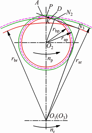
Figure 2 Geometric model of planetary gear with inner gear
2.2 Dynamic model of planetary gear train
For high-speed and heavy-duty gear systems, the damping ratio and inertial forces have significant effects on the transmission characteristics, and thus, dynamic analysis is necessary. The dynamic model of the planetary train was established accounting for the excitation of the time-varying meshing stiffness [23-25]. The dynamic model is shown in Figure 3.
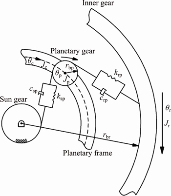
Figure 3 Dynamic model of planetary gear train
For the inner gear, there is
 (1)
(1)
where Jr represents the moment of inertia of the inner gear, ��r is the torsional angular displacement induced by the vibration, krp and crp are the meshing stiffness and damping between the planetary gear and the inner gear, respectively, ��rp is the displacement of the planetary gear and the inner gear at point K along the line of action (LOA), and Tp is the input torque.
For the planetary gear, there is
 (2)
(2)
where Jp represents the moment of inertia of the planetary gear, ��p is the torsional angular displacement caused by the vibration, ksp and csp are the meshing stiffness and damping between the planetary gear and sun gear, respectively, and ��sp is the displacement of the planetary gear and the sun gear at point K along the line of action.
For the planetary frame, there is

 (3)
(3)
where Jc represents the moment of inertia of the planetary frame, ��c is the torsional angular displacement due to the vibration, mp denotes the mass of the planetary gear, and rc is the effective radius of the planetary frame.
For the planetary gear and the internal gear, the working pressure angle is ��rp, and for the planetary gear and the sun gear, the working pressure angle is ��sp. The damping coefficients are expressed as follows:
 ;
;
 .
.
According to the analysis of WANG et al [7], the values of ��rp and ��sp are generally 0.03-0.17. Thus, in this work, ��rp=��sp=0.1.
The Weber method [26] was used to determine the time-varying meshing stiffness ksp and krp. The displacements are calculated as follows:
 ,
,
 (4)
(4)
The lubrication of the oil film krp must be corrected to obtain
 (5)
(5)
where kh represents the oil film stiffness.
The dynamic load for the meshing teeth between the planetary gear and the inner gear is
 (6)
(6)
The fluctuating velocity induced by the vibration of the inner gear is
 (7)
(7)
The fluctuating velocity induced by the vibration of the planetary gear is
 (8)
(8)
The dynamic component of the entrainment velocity due to the vibration can be written as
 (9)
(9)
2.3 Lubrication model
2.3.1 Basic contact parameters for planetary and inner gears
As depicted in Figure 2, according to the properties of the involute curve, the instantaneous radii of curvature at any possible meshing point K are as follows:
 ,
,
 (10)
(10)
where s denotes the distance from the meshing point K to the pitch point P.
The value of ��rp can be obtained by the following equation:
 (11)
(11)
where z3 and z2 denote the tooth number of the inner gear and the planetary gear, respectively, and the modification coefficients are denoted as x3 and x2, respectively.
The comprehensive radius of curvature at any possible meshing point K is
 (12)
(12)
The linear velocities of the planetary and inner gears are as follows:
 (13)
(13)
where  and
and 
The entrainment velocity is as follows:
 (14)
(14)
where U0 is the steady value of entrainment velocity without consideration of the vibrations:

where u denotes the fluctuation of entrainment velocity induced by vibration and its value can be given by Eq. (9).
2.3.2 Governing equations for lubrication
The generalized Reynolds equation is as follows [14]:
 (15)
(15)
where p denotes oil film pressure (Pa), and h denotes oil film thickness (m). Equivalent parameters such as ��*, ��e and (��/��)e are concerned with the viscosity �� and density �� of the lubricant.
w is the load (N/m), and the oil film pressure must satisfy the following equation:
 (16)
(16)
when considering the effect of vibration, w is the dynamic load, i.e., w=Fd.
The equation of oil film thickness is as follows:
 (17)
(17)
where h0 is the central film thickness of the rigid body and E is the overall elastic modulus of those two contact surfaces.
A Ree�CEyring fluid was used for the analysis, and its constitutive equation is as follows:
 (18)
(18)
where ��0 is the feature shear stress, and �� is the apparent viscosity.
The equivalent viscosity is defined as follows:
 (19)
(19)
Thus, the equivalent viscosity function can be written as
 (20)
(20)
Other governing equations applied for lubrication, such as the equation of oil film thickness, viscosity�Cpressure equation, density- pressure equation, and the energy equation, can be given by Ref. [9].
2.4 Model of oil film stiffness
2.4.1 Global method
Figure 4 shows the model for calculating oil film stiffness based on the ��global method��. At each node in the Hertz contact zone, the oil film can be assumed to be some parallel small springs, and the oil film stiffness can be obtained by adding the stiffness of these small springs together [27].
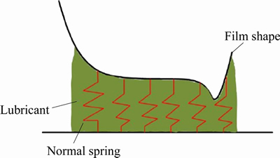
Figure 4 Model of oil film stiffness
The specific formula to calculate the oil film stiffness using the global method is as follows:
 (21)
(21)
where n1 denotes the node in the inlet zone, n2 denotes the node in the outlet zone, ��fi represents the difference in the load at node i, which can be expressed as follows:

where B0 is the tooth width of the gear, ��x denote the distance between two adjacent nodes on the grid, and pi represents the oil film pressure at node i.
For the oil film thickness, the corresponding change is as follows:

This method can capture the oil film pressure and thickness of each node in the Hertz contact zone and has certain practicability.
2.4.2 Average method
The formula for calculating the oil film stiffness using the averaging method is as follows:
 (22)
(22)
 (23)
(23)
where and ��f denote the difference in the average oil film thickness and load, respectively. We adopted the average method to correct krp in Eq. (5).
3 Numerical method
The governing equations for lubrication described above can be solved by the Gauss-Seidel iteration method and the corresponding boundary conditions can be found elsewhere [6]. The Reynolds equation was calculated using a uniform grid based on the finite difference method. The solution of oil film pressure can be obtained by the multigrid technique. The column scanning technique was applied to determine oil film and surface temperature. The multigrid method utilized the W-cycle, and the steps involved in to obtain a converged solution are shown clearly in Ref. [28]. The solution of elastic deformation was obtained by the multilevel multi-integration method [28]. Six levels of grids were applied to calculate the oil film thickness and pressure. In the X direction, there were 961 nodes on the finest level and the real domain for the infinite line contact was between Xin=-4.6 and Xout=1.4, where the subscripts in and out indicate the inlet and outlet, respectively. Along the line of action, the calculation process for transient Reynolds equation was divided in 180 time steps. Based on the multigrid method, the pressure is needed to be relaxed on each grid level.
Based on the dynamic model, the calculation flow chart for the analysis of the lubrication performance under different modification coefficients is shown in Figure 5.
As depicted in Figure 5, the relative error for the vibration displacement and velocity are denoted as ERR(��) and ERR(u), respectively, and ERR(kh) represents the relative error for the oil film stiffness. The convergence criteria were defined as follows:


 .
.
4 Results and discussion
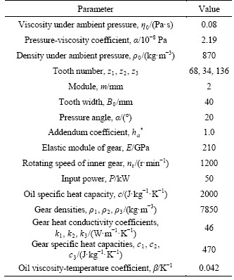
The basic parameters for the gear transmission and lubrication are shown in Table 1.
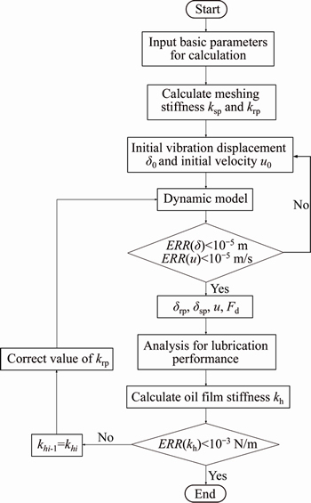
Figure 5 Calculation flow chart for analysis of lubrication performance with different modification coefficients
Table 1 Basic parameters for calculation
4.1 Influence of different transmission types on lubrication
The lubrication performances of different transmission types were analyzed based on the simplified static load model. The different transmission types were as follows:
Positive drive:  ,
,
Negative drive:  ,
,
Equivariant drive: 

 ,
,
Standard drive: 
 .
.
Figure 6 shows the distribution of the load along the line of action. S denotes the distance from the meshing point to the pitch point, and S=0 denotes the position of the pitch point. In Zones I and III, there were two pairs of meshing teeth. However, in Zone II, there was only one pair of meshing teeth.

Figure 6 Load spectrum of gear system
Figure 7 shows the variations of the comprehensive radius of curvature, entrainment velocity, and slide-roll ratio. The modification coefficient had significant influence on the tooth profile. Among the different transmission types, both the comprehensive radius of curvature and the entrainment velocity were the largest when the positive drive was used. For the negative drive, the comprehensive radius of curvature was the smallest, leading to the smallest entrainment velocity. The inner gear was active. As shown in Figure 2, A was the engage-in point. Based on the properties of the involute curve, the comprehensive radius of curvature decreased consistently in the transmission process. Affected by the comprehensive radius of curvature, the entrainment velocity continued to decrease.

Figure 7 Transmission characteristics of gear system:
Regardless of the type of transmission, over the whole process, the slide-roll ratio increased constantly. The difference in the slide-roll ratio was too small initially, but after the pitch point, it was enlarged. The slide-roll ratio of the negative drive exceeded that of the other three transmission types gradually.
Figure 8 shows the performance of the gear system. Figures 8(a)-(c) show the variation of the central oil film thickness and pressure (hc and pc), minimum oil film thickness, and friction coefficient (hmin and f) as well as the flash temperature of the oil film in dimensionless form (Tmax/T0).
As depicted in Figure 8, affected by the entrainment velocity, the central and minimum oil film thickness decreased consistently, leading to an increasing friction coefficient. Compared with the other three transmission types, the oil film thickness of the positive drive was the largest, and its friction coefficient was the smallest.
The flash temperature of the oil film in dimensionless form (Tmax/T0) and the central oil film pressure (pc) exhibiting similar trends were both influenced by the load (w) significantly. In Zone I, because of the increasing load and slide-roll ratio, the value of the flash temperature continued to increase. In Zone II, the load was the largest. Thus, the value of the flash temperature increased dramatically when the meshing point K varied from Zone I to Zone II. With the decrease in the oil film thickness, at the last point (C-) of Zone II, the value of the flash temperature reached its peak. In Zone III, although the slide-roll ratio continued to increase, the linear velocities of the planetary and inner gears were low, leading to a low shearing rate between the lubricant molecules. Meanwhile, the load continued to decrease. Thus, in Zone III, the value of the flash temperature decreased slightly.
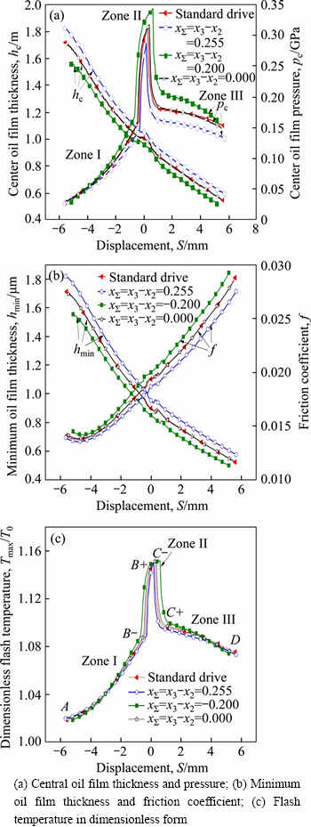
Figure 8 Lubrication performance of the gear system:
When gear pairs are subjected to heavy loads, the lubricant film can rupture and consequently cannot separate the tooth surfaces adequately, leading to scuffing. The minimum oil film thickness and the flash temperature of the oil film are two important indictors for evaluating the scuffing load capacity. As shown in Figures 8(b) and (c), at the last point of Zone II and the recess point (C- and D, respectively), the value of the flash temperature was high, while the minimum oil film thickness was small, which could easily lead to scuffing failure. Thus, C- and D were two dangerous points for lubrication.
Figure 9 depicts the distribution of the oil film stiffness along the line of action (LOA). When the load was unchanged, in the analysis of the lubricating performance within different transmission types, the oil film thickness of the positive drive was the largest. A thicker oil film corresponded to an increase in the distance between the lubricant molecules as well as a decrease in the intermolecular repulsion. The smaller intermolecular repulsion between the lubricant molecules was, the more easily the oil film was compressed, which meant that the oil film stiffness was smaller. Consequently, the oil film stiffness of the positive drive was the smallest. On the contrary, the oil film stiffness of the negative drive was the largest. Regardless of the type of transmission, at the last point (C-) of Zone II, the oil film stiffness reached its peak.

Figure 9 Oil film stiffness under different transmission types
4.2 Influence of different modification coefficients on lubrication
Based on the above analyses of the different transmission types, the positive drive exhibited the best lubricating performance. Because the above analyses were based on a simplified static load model, in this section, analyses of the lubrication characteristics under different modification coefficients were carried out for the positive drive based on the dynamic model. The basic parameters for the calculation are shown in Table 2. Among these basic parameters, the modification coefficient of the external meshing and internal meshing
  are noteworthy.
Table 2 Basic parameters for calculation

4.2.1 Analysis of dynamic characteristics
Figure 10(a) shows the time-varying meshing stiffness between the planetary gear and the internal gear. The time-varying meshing stiffness between the sun gear and the planetary gear is shown in Figure 10(b).
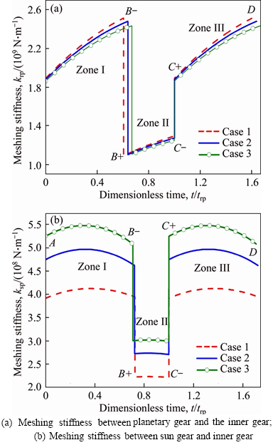
Figure 10 Time-varying meshing stiffness of external and internal meshing:
For the external meshing, with the increase in the modification coefficient  , the meshing stiffness between the sun gear and the planetary gear (ksp) increased. In contrast, for the internal meshing, the meshing stiffness between the inner gear and the planetary gear (krp) decreased with the increase in the modification coefficient
  . For both the external meshing and internal meshing, at the alternation points (B and C) of the different zones, the meshing stiffness changed dramatically, leading to tooth-change impact.
Figure 11 shows the dynamic characteristics of the gear system. As shown in Figure 10, when the modification coefficients and
and were unchanged, the values of ��rp and u were much larger in Zone II compared with the other two zones (Zones I and III). The reason was that there was only one pair of teeth meshing in Zone II, and the values of meshing stiffness (krp and ksp) were smaller. The distribution of ��rp and u also illustrated that the stability of the transmission in Zone II was poor. The value of krp exceeded that of ksp, so that the variations of the dynamic characteristics were mainly influenced by krp. With the increase in the modification coefficients, the meshing stiffness between the planetary gear and the inner gear (krp) decreased, which led to increases in ��rp and u. The variation of the dynamic load was influenced by ��rp, and u affected the fluctuation of the entrainment velocity.
The load spectrum of the gear system is shown in Figure 12, which reflects the variation of the dynamic load. With the increase in the modification coefficients and the steady value of dynamic load decreased slightly. However, near the engage-in point (A) and the alternation points (B and C), the vibration amplitude of the dynamic load increased. In addition, the vibration frequency was weakened, which means that the engage-in and tooth-change impacts were intensified. This was mainly caused by a decreasing meshing stiffness (krp) between the planetary gear and the inner gear.
4.2.2 Analysis of lubrication performance
Figure 13 shows the lubrication characteristics determined using the dynamic model. With the increase in the modification coefficients and the minimum oil film thickness increased while the friction coefficient (f) and the flash temperature of the oil film (Tmax/T0) in dimensionless form decreased consistently, which indicated that the lubrication performance was further improved. From the perspective of the mechanism, this is consistent with the result in Figure 7, which was mainly caused by the increasing comprehensive radius of curvature and entrainment velocity.
Figure 13(a) also shows that, near the engage- in point (A), the vibration stability of the oil film was weakened with the increase in the modification coefficients. The main manifestation was the increasing vibration amplitude of the minimum oil film thickness, which indicated that the oil film stiffness was undermined. In other words, the increasing modification coefficients and led to a decrease in the oil film stiffness. The reason for this phenomenon is shown in Figure 16.
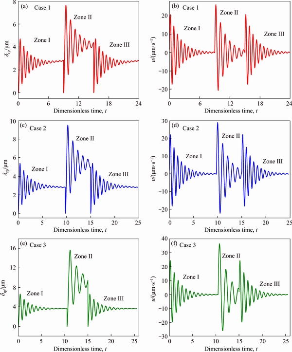
Figure 11 Displacement along line of action at point K for planetary gear and inner gear (a, c, e) and dynamic component of entrainment velocity (b, d, f)
As shown in Figure 13(a), when the modification coefficients were unchanged, comparing the vibration amplitudes and frequencies of the oil film in segments AB, BC and CD, the vibration stabilities of the oil films in segments BC and CD were better than that in segment AB. This indicated that the oil film stiffnesses in segments BC and CD were larger than that in segment AB. This is consistent with the results in Figure 9. The oil film stiffness in different segments indicated that compared with the tooth-change impact at points B and C, the engage-in impact at point A was more likely to cause oscillations of the oil film, which would have an adverse effect on the lubrication. Therefore, for the positive drive, although increasing the modification coefficient could improve the lubrication characteristics of the system, it should be within a reasonable range or the gear tooth profile should be modified appropriately to reduce the engage-in impact.

Figure 12 Dynamic load spectrum of gear system
The friction coefficient and flash temperature of the oil film are greatly affected by the load. As shown in Figures 13(b) and (c), with the increase in the modification coefficient, the vibration amplitude of the flash temperature and friction coefficient increased, while the vibration frequency decreased constantly. This was mainly because the engage-in impact and tooth-change impact were continuously strengthened because of the increasing modification coefficient.
Figure 14 shows the transient temperature variations in dimensionless form (T/T0) at point C- under different modification coefficients. According to the above analysis, C- was a dangerous point for the lubrication. As shown in Figure 14, the temperature of the oil film decreased gradually with the increase in the modification coefficients.
4.3 Discussion of oil film stiffness
4.3.1 Influence of entrainment velocity on oil film stiffness
Figure 15 shows the variation of the oil film stiffness at the pitch point with the entrainment velocity, where kglo and kave denote the oil film stiffness determined using the global method and the average method, respectively. With the increase in the entrainment velocity, the oil film stiffness decreased continuously. This was mainly because increasing the entrainment velocity led to an increase in the oil film thickness and the distance between lubricant molecules, which resulted in decreased intermolecular repulsion. With the load unchanged, the thicker the oil film was, the more easily it was compressed, which meant that the oil film stiffness was smaller.
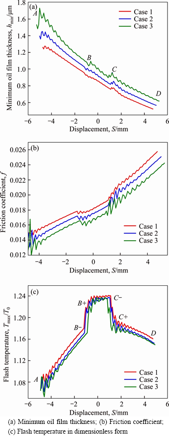
Figure 13 Comparison of lubrication characteristics:
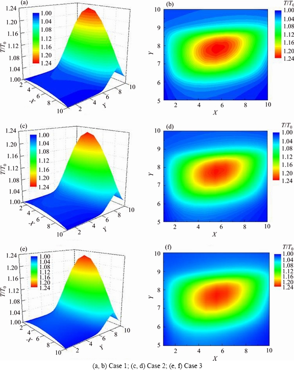
Figure 14 Transient temperature distribution at point C-:
4.3.2 Influence of modification coefficient on oil film stiffness
Figure 16 shows the variation of the oil film stiffness at the pitch point with the modification coefficient. According to the analysis in Figure 7, increasing the modification coefficient led to an increase in the entrainment velocity. Thus, as shown in Figure 16, with the increase in the modification coefficient, the oil film stiffness decreased continuously, which was consistent with the conclusion obtained in Figure 13(a).
5 Conclusions
Considering the modification coefficient, time-varying meshing stiffness, and oil film stiffness comprehensively, the thermal elastohydrodynamic lubrication performances for internal meshing gear pair are analyzed based on a simplified static model and a dynamic model. The conclusions are stated as follows:
1) Compared with a standard drive, the positive drive could improve the lubrication conditions of the gear system and enhance the scuffing load capacity. In contrast, the negative drive worsens the lubrication condition and undermines the scuffing load capacity.
2) When the positive drive is adopted, with the increase in the modification coefficient, the oil film thickness increases, while the friction coefficient and the highest temperature rise ratio of the oil film decrease continuously, which indicates that the lubrication performance is continuously improved. Although increasing the modification coefficient could improve the lubrication characteristics of the system, it should be kept within a reasonable range to reduce the engage-in impact and tooth-change impact.
3) With the increment in the entrainment velocity, the oil film stiffness decreases. For the modified gear transmission, an increase in the modification coefficient leads to a decrease in the oil film stiffness.

Figure 15 Oil film stiffness of pitch point under different entrainment velocities

Figure 16 Oil film stiffness of pitch point under different modification coefficients
Contributors
The overarching research goals were developed by JIAN Guang-xiao and WANG You-qiang. JIAN Guang-xiao and WANG You-qiang put forward the research ideas. JIAN Guang-xiao, WANG You-qiang, ZHANG Ping, LI Yun-kai and LUO Heng established the models. JIAN Guang-xiao debugged the program, got the research data and accomplished the relevant analysis. The initial draft of the manuscript was written by JIAN Guang-xiao. All authors replied to reviewer�� comments and revised the final version.
Conflict of interest
JIAN Guang-xiao, WANG You-qiang, ZHANG Ping, LI Yun-kai and LUO Heng declare that they have no conflict of interest.
References
[1] HUANG Xing-bao, WANG You-qiang. Transient elastohydrodynamic lubrication analysis of spur gears under dynamic conditions [J]. Lubrication Engineering, 2015, 40(11): 65-70. DOI: 10.3969/j.issn.0254-0150.2015.11.013.
[2] WANG Wen-zhong, CAO Hong. Numerical simulation of unsteady EHL lubrication of involute helical gears [J]. Tribology, 2011, 31(6): 604-609. DOI: 10.16078/j.tribology. 2011.06.015.
[3] SHI Gao-wei, WANG You-qiang. Influence of variable coiling and suction speed process on hot mixed lubrication of spur gear [J]. Lubrication Engineering, 2011, 36(1): 43-48. DOI: 10.3969/j.issn.0254 -0150.2011.01.012.
[4] BAO Pei-de. Study on elastohydrodynamic lubrication of planetary gear transmission [J]. Lubrication Engineering, 2011, 36(2): 12-16. DOI: 0254-0150 (2011) 2-012-5.
[5] DAI Ling, PU Wei, WANG Jia-xu. Mixed EHL analysis of planetary drives with small teeth number difference considering real tooth geometry [J]. Lubrication Science, 2018, 30(6): 317-330. DOI: 10.1002/ls.1423.
[6] ZHAO Jing-jing, WANG You-qiang, ZHANG Ping, JIAN Guang-xiao. A Newtonian thermal elastohydrodynamic lubrication model for ferrofluid-lubricated involute spur gear pair [J]. Lubrication Science, 2020, 32(2): 33-45. DOI: https://doi. org/10.1002/ls.1483.
[7] WANG K L, CHENG H S. A numerical solution to the dynamic load, film thickness, and surface temperatures in spur gears, Part I: Analysis [J]. Transactions of the ASME, 1981, 103(1): 177-187. DOI: 10.1115/1.3254859.
[8] WANG K L, CHENG H S. A numerical solution to the dynamic load, film thickness, and surface temperatures in spur gears, Part II: Results [J]. Transactions of the ASME, 1981, 103(1): 188-194. DOI: 10.1115/1.3254860.
[9] WANG You-qiang, HE Zhi-cheng. Effect of impact load on transient elastohydrodynamic lubrication of involute spur gears [J]. Tribology Transactions, 2012, 55(2): 155-162. DOI: 10.1080/10402004.2011.639048.
[10] De la CRUZ M, CHONG W W F, TEODORESCU M, THEODOSSIADES S. Transient mixed thermo- elastohydrodynamic lubrication in multi-speed transmissions [J]. Tribology International, 2012(49): 17-29. DOI: 10.1016/j.triboint. 2011.12.006.
[11] XUE Jian-hua, LI Wei, QIN Cai-yan. The scuffing load capacity of involute spur gear systems based on dynamic loads and transient thermal elastohydrodynamic lubrication [J]. Journal of Central South University (Science and Technology), 2014, 45(8): 2603-2609. (in Chinese)
[12] LI S, KAHRAMAN A. A spur gear mesh interface damping model based on elastohydrodynamic behavior [J]. International Journal of Powertrains, 2011, 1(1): 4-21. DOI: 10.1504/ijpt.2011.041907.
[13] LI S, KAHRAMAN A. A tribo-dynamic model of a spur gear pair [J]. Journal of Sound and Vibration, 2013, 332: 4963-4978. DOI: 10.1016/j.jsv.2013.04.022.
[14] KANG Meng-ru. A study of quasi-static and dynamic behavior of double helical gears [M]. Ohio: The Ohio State University, 2014.
[15] BARBIERI M, LUBRECHT A A, PELLICANO F. Behavior of lubricant fluid film in gears under dynamic conditions [J]. Tribology International, 2013, 62: 37-48. DOI: 10.1016/ j.triboint.2013.01.017.
[16] HUANG Xing-bao, YANG Bin-tang. A nano lubrication solution for high-speed heavy-loaded spur gears and stiffness modelling [J]. Applied Mathematical Moedlling, 2019, 5(6): 262-272. DOI: 10.1016/j.apm.2019.03.008.
[17] ZHANG Yuan-yuan, LIU Huai-ju. Oil film stiffness and damping in an elastohydrodynamic lubrication line contact-vibration [J]. Journal of Mechanical Science and Technology, 2016, 30(7): 3031-3039. DOI: 10.1007/ s12206-016-0611-x.
[18] ZHOU Chang-jiang, XIAO Ze-liang, CHEN Si-yu, HAN Xu. Normal and tangential oil film stiffness of modified spur gear with non-Newtonian elastohydrodynamic lubrication [J]. Tribology International, 2016, 70(2): 112-120. DOI: 10.1016/j.triboint.2016.12.045.
[19] ZOU Yu-jing, CHANG De-gong. Coupling analysis of dynamics and EHL for spur gears [J]. Journal of Aerospace Power, 2016, 31(4): 2010-2020. DOI: 10.13224/j.cnki. jasp.2016.08.028.
[20] YUAN Shi-hua, DONG Hui-li, LI Xue-yuan. Analysis of lubricating performance for involute gear based on dynamic loading theory [J]. Journal of Mechanical Design, 2012, 134(12): 1-9. DOI: 10.1115/1.4007842.
[21] DONG Hui-li, YUAN Shi-hua, LI Xue-yuan. Analysis of lubricating performance for involute gear considering tribo-dynamic behavior [J]. Tribology, 2013, 33(5): 436-442. DOI: 10.16078/j.tribology.2013.05.012.
[22] YUAN Shi-hua, DONG Hui-li, LI Xue-yuan. Dynamic loading analysis of involute gears considering lubrication performance [J]. Journal of Mechanical Engineering, 2012, 48(19): 10-16. DOI: 10.3901/jme.2012.19.010.
[23] PAN Bo, SUN Jing, YU Deng-yun, HU Hua-jun. Research on dynamic modeling and analysis of spur-planetary gear [J]. Journal of Dynamics and Control, 2018, 16(2): 121-128. DOI: 10.6052/1672-6553-2018-002.
[24] SUN Tao, SHEN Yun-wen, SUN Zhi-min, LIU Ji-yan. Study on nonlinear dynamic behavior of planetary gear train dynamic model and governing equations [J]. Journal of Mechanical Engineering, 2002, 38(3): 1-10.
[25] LI Run-fang, WANG Jian-jun. Gear system dynamics [M]. Beijing: Science Press, 1997. (in Chinese)
[26] TANG Jin-yuan, CAI Wei-xing, WANG Zhi-wei. Meshing stiffness formula of modification gear [J]. Journal of Central South University (Science and Technology), 2017, 48(2): 337-342. DOI: 10.11817/j.issn.1672-7207.2017.02.010. (in Chinese)
[27] JIAN Guang-xiao, WANG You-qiang, ZHANG Ping, XIE Yi-nong. Analysis of lubricating performance for involute spur gear under vibration [J]. Lubrication Science, 2020, 32(7): 344-357. DOI: https://doi.org/10.1002/ls.1507.
[28] YANG Pei-ran. Numerical analysis of fluid lubrication [M]. Beijing: National Defense Industry Press, 1998. (in Chinese)
(Edited by FANG Jing-hua)
���ĵ���
�����������ϳ��ָ������Է���
ժҪ��Ϊ̽�����غ����������dz��ֵ��ȵ��������ԣ��ۺϿ��DZ�λϵ����ʱ�����ϸնȵ�Ӱ�죬���ڶ���ѧ���ۣ��������dz���ϵͳ�Ķ���ѧģ�ͣ��������뾲�غ������±�λ����ϵͳ���ȵ��������ԡ��о�����������������������ȣ�����������ʱ�����dz������ڳ�������ʱ����Ч����ѣ��ֳݼ�����γɽϺ������Ĥ���ֳݼ��Ħ��ϵ������Ĥ�����������С�����ң��������dz������ڳ��ֱ�λϵ����������״�����ϵõ����ƣ��Ƚ��ϳ���������ǿ�����dz������ڳ��ֱ�λϵ�������ӽ����������ϸնȣ��������������ͻ��ݳ����ͬʱ��������Ĥ�ĸնȡ�
�ؼ��ʣ����dz��֣�����ѧģ�ͣ���λϵ���������ԣ���Ĥ�ն�
Foundation item: Projects(51575289, 51705270) supported by the National Natural Science Foundation of China
Received date: 2020-03-14; Accepted date: 2020-07-22
Corresponding author: WANG You-qiang, PhD, Professor; Tel: +86-18660279607; E-mail: wyq1970301@126.com; ORCID: https:// orcid.org/0000-0001-9228-6621
Abstract: The thermal elasto-hydrodynamic lubrication characteristics of the internal meshing gears in a planetary gear train under vibrations were examined considering the influence of the modification coefficient and time-varying meshing stiffness. Based on dynamic theory of the gear system, a dynamic model of the planetary gear train was established. The lubrication performances of modified gear systems under vibrations and static loads were analyzed. Compared with other transmission types, the best lubrication effect could be produced by the positive transmission. A thicker lubricating oil film could be formed, and the friction coefficient and oil film flash temperature are the smallest. Increasing modification coefficient improves the lubrication performance continuously but intensifies the engage-in and tooth-change impact. For the planetary and inner gears, the increase in the modification coefficient also leads a decrease in the oil film stiffness.
