
J. Cent. South Univ. Technol. (2008) 15: 901-905
DOI: 10.1007/s11771-008-0164-y
![]()
Fast algorithm and numerical simulation for
ray-tracing in 3D structure
GAO Er-gen(�߶���)1, 2, ZHANG An-jia(�Ű���)3, HAN Uk4, SONG Shu-yun(������)1, ZHAI Yong-bo(������)1
(1. School of Earth and Space Sciences, University of Science and Technology of China, Hefei 230026, China;
2. Research Center of Oil and Nature Gases, University of Science and Technology of China, Hefei 230026, China;
3. Institute of Geophysics, Chinese Academy of Sciences, Beijing 100101, China;
4. Department of Environmental Sciences, Korea Military Academy, Seoul 139799, Korea)
Abstract:
Beginning with the method of whole path iterative ray-tracing and according to the positive definiteness of the coefficient matrix of the systems of linear equations, a symmetry block tridiagonal matrix was decomposed into the product of block bidiagonal triangular matrix and its transpose by means of Cholesky decomposition. Then an algorithm for solving systems of block bidiagonal triangular linear equations was given, which is not necessary to treat with the zero elements out of banded systems. A fast algorithm for solving the systems of symmetry block tridiagonal linear equations was deduced, which can quicken the speed of ray-tracing. Finally, the simulation based on this algorithm for ray-tracing in three dimensional media was carried out. Meanwhile, the segmentally-iterative ray-tracing method and banded method for solving the systems of block tridiagonal linear equations were compared in the same model mentioned above. The convergence condition was assumed that the L-2 norm summation for mk, 1 and mk, 2 in the whole ray path was limited in 10-6. And the calculating speeds of these methods were compared. The results show that the calculating speed of this algorithm is faster than that of conventional method and the calculated results are accurate enough. In addition, its precision can be controlled according to the requirement of ray-tracing.
Key words:
ray-tracing; seismic migration; Cholesky decomposition; tomography��
1 Introduction
At present, 3D seismic migration and tomography method based on seismic wave theory has been extensively used. One important task in seismic migration and tomography is ray-tracing. In the process of seismic migration and tomography, a great amount of ray paths, travel-times and amplitudes of seismic wave, which pass through the interior media of the earth, will be traced and calculated. The calculation of ray-tracing takes up the main spending of seismic migration and seismic tomography. Its calculating speed and precision will influence the effect of seismic migration and tomography directly[1-6]. Therefore, it is very significant to seek a fast and accurate ray-tracing algorithm for seismic migration and tomography.
In recent years, many geophysicists have conducted a great number of researches to promote the speed of calculation and precision of ray-tracing. They put forward many algorithms of fast ray-tracing successively and some of them were applied in practice[7-16]. However, these algorithms do not meet the requirements for the speed and precision of the ray-tracing in data processing of spot seismic migration and tomography. Thus, it is an industrious goal of geophysicists to improve calculating speed and precision of ray-tracing further. In order to improve the speed of ray-tracing in 3D arbitrary interface, GAO et al[17] proposed a method of whole path iterative ray-tracing. Although this method could realize ray- tracing and improve calculating speed after adopting conventional method to solve system of banded equations, there is still potential to improve calculating speed. In this work, based on the property of coefficient matrix, the coefficient matrix was decomposed into multiplication of the block upper bidiagonal matrix and the block lower bidiagonal matrix by means of Cholesky decomposition[18]. And hereby an algorithm to solve the symmetry block positive definite matrix equation sets was proposed.
2 Recast of symmetry block positive definite tridiagonal matrix
The system of matrix equations for ray-tracing in Ref.[16] can be expressed as follows:
![]() (1)
(1)
where
 (2)
(2)
![]() (3)
(3)
![]() (4)
(4)
Each expression of variables above refers to Ref.[17]. For the sake of marked convenience for designing a fast algorithm, the elements of each blocked matrix in Eqns.(2-4) are further expressed as follows:
![]()
![]()
where i=1, 2, ��, n.
In the following section, system of Eqn.(1) can be solved according to the property of the coefficient matrix by adopting fast algorithm.
3 Solution to systems of symmetry block positive definite tridiagonal linear equations
The coefficient matrix ![]() of system of Eqn.(1) is a symmetry positive definite matrix. So coefficient matrix
of system of Eqn.(1) is a symmetry positive definite matrix. So coefficient matrix ![]() can be decomposed by means of Cholesky decomposition as follows[18]:
can be decomposed by means of Cholesky decomposition as follows[18]:
![]() (5)
(5)
where ![]() is the lower triangular matrix.
is the lower triangular matrix.
Since ![]() is a symmetry block tridiagonal matrix, i.e. it takes the form of coefficient matrix of Eqn.(2). Therefore, matrix
is a symmetry block tridiagonal matrix, i.e. it takes the form of coefficient matrix of Eqn.(2). Therefore, matrix ![]() can actually be written as
can actually be written as

Matrix Lk,k above is a 2��2 lower triangular matrix (k=1, 2, ��, n); Lk, k-1 (k=2, 3, ��n) is a 2��2 matrix. Lk, k and Lk, k-1 can be figured out in turn. Matrix L1,1 can be solved by
![]() =A1 (6)
=A1 (6)
Each element of matrix L1,1 is given by
l1,1,1,1=(a1,1,1)1/2, l1,1,2,1=a1,1,2/l1,1,1,1, l1,1,2,2=(a1,2,2-![]() )1/2.
)1/2.
Meanwhile, Lk,k-1 (k=2, 3, ��, n) satisfies
![]() (7)
(7)
and Lk-1,k-1 is a 2��2 lower triangular matrix. Thus the elements of matrix Lk,k-1 can be respectively solved and described as
lk, k-1, 1, 1=bk-1, 1, 1/lk-1, k-1, 1, 1,
lk, k-1, 1, 2=(bk-1, 2, 1-lk-1, k-1, 2, 1 lk, k-1, 1, 1)/lk-1, k-1, 2, 2,
lk, k-1, 2, 1=bk-1, 1, 2/lk-1, k-1, 1, 1,
lk, k-1, 2, 2=(bk-1, 2, 2-lk-1, k-1, 2, 1lk, k-1, 1, 2)/lk-1, k-1, 2, 2.
Each matrix Lk, k (k=2, 3, ��, n) can be obtained by solving the following systems of equations respectively
![]() (8)
(8)
The solution to Eqn.(8) is analogous to that of Eqn.(6). After replacing ![]() with
with ![]() Eqn.(1) is decomposed into
Eqn.(1) is decomposed into
![]() (9)
(9)
In order to get the solution to unknown vector ![]() Eqn.(9) is split into the following two systems of equations
Eqn.(9) is split into the following two systems of equations
![]() (10)
(10)
![]() (11)
(11)
where ![]()
Solving Eqn.(10) to get vector ![]() and then, to get unknown vector
and then, to get unknown vector ![]()
In the procedure of solving the systems of linear equations ![]() the systems of equations
the systems of equations ![]() d1 is first solved. Because of a 2��2 lower triangular matrix of L1,1, the solution to vector
d1 is first solved. Because of a 2��2 lower triangular matrix of L1,1, the solution to vector ![]() is
is
![]()
![]()
From the kth block of Eqn.(10), the following equation can be gotten
![]() (12)
(12)
After transposition, Eqn.(12) can be expressed as
![]() (13)
(13)
By getting ![]() in the same way mentioned above
in the same way mentioned above ![]() can be solved. By successively carrying out this procedure the solution to the unknown vector
can be solved. By successively carrying out this procedure the solution to the unknown vector ![]() can be gotten.
can be gotten.
Following the above method, the solution of equation below can be gotten
![]() (14)
(14)
But, matrix ![]() is an upper triangular matrix, the equation with respect to mn must be solved first, that is
is an upper triangular matrix, the equation with respect to mn must be solved first, that is
![]() (15)
(15)
![]() is a 2��2 upper triangular matrix, one can get
is a 2��2 upper triangular matrix, one can get
![]()
![]()
For the kth block row of system of Eqn.(11), the following equation will be satisfied
![]() (16)
(16)
After transposition, Eqn.(16) can be written as
![]() (17)
(17)
Using the same method as solving vector mn, one can get the solution of vector mk. Finally, fast algorithm of ray-tracing is realized.
4 Numerical simulationIn order to test the calculating speed, precision and stability of the algorithm for ray-tracing in 3D structure and to compare with the banded matrix method (the method that directly solves the systems of block tridiagonal equations by means of the method that solves the systems of banded equations) and the method in GAO et al[16], numerical calculations were carried out with models shown in the following cases. In these cases, convergence condition is assumed that the L-2 norm summation for mk, 1 and mk, 2 in the whole ray path is limited in 10-6. At the same time, to compare the calculating speed between these three methods, the ratios of computer��s CPU time cost in the procedure of numerical simulations for the above methods were taken as the comparative parameters.
4.1 Planar layered media model (Model 1)
Fig.1 shows an illustration of common shot point ray-tracing in three-layer plane interface. The first layer interface function is z1=200 m, and the velocity is 2.5 km/s; the second layer interface function is z2=400 m, and the velocity is 3.5 km/s; and the third layer interface function is z3=600 m, and the velocity is 5.0 km/s. The substrate medium velocity is 5.5 km/s. In Fig.1, the results obtained by the methods in Ref.[16], the banded method and the method in this work are overlapped. Fig.1(a) shows a result of ray-tracing for transmission wave ray path of common shot point for three kinds of methods. Source locates in subterranean. Receiver is on the earth��s surface, and the interval between two courses is 50 m. Fig.1(b) shows a result of ray-tracing for reflection wave for three kinds of method. Source and receiver are located at the earth��s surface. The interval is also 50 m.
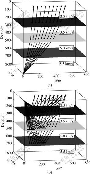
Fig.1 Results of ray-tracing for three-layer planar interface structure (����Method in Ref.[16];![]() ��Banded method; *��Method in this work): (a) Transmission wave; (b) Reflection wave
��Banded method; *��Method in this work): (a) Transmission wave; (b) Reflection wave
4.2 Arbitrary interface media model (Model 2)
Fig.2(a) shows a three-layer arbitrary interface model for common shot point ray-tracing of transmission wave for three kinds of methods. Source locates in subterranean. Receiver is on the earth��s surface. Interval between two courses is 50 m. The interfacial function of the first subsurface is z1=200-30sin(x/100)+40cos(y/200), and the medium velocity is 2.0 km/s; the interfacial function of the second subsurface is z2=500- [(x-500)/50]2+[(y-400)/50]2, and the medium velocity is 3.0 km/s; the interfacial function of the third subsurface is z3= 700-30cos(x/100)+40sin(y/200), and the velocity is 5.0 km/s. The substrate medium velocity is 6.5 km/s. In Fig.2, the results obtained by the method in Ref.[16], the banded method and the method in this work are overlapped. Fig.2(b) shows the results of common shot point ray-tracing for reflection wave by the three kinds of method in the above model. Source and receivers are located at the surface. All parameters are the same as those in Fig.2(a).
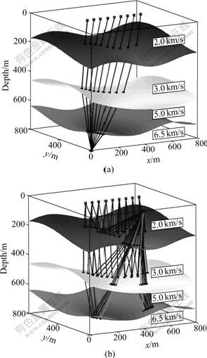
Fig.2 Results of ray-tracing for three-layer arbitrary interface structure (����Method in Ref.[16];![]() ��Band method; *��Method in this work): (a) Transmission wave; (b) Reflection wave
��Band method; *��Method in this work): (a) Transmission wave; (b) Reflection wave
4.3 Comparison of calculation speeds
In the two numerical simulations above, after adopting the ratios of computer��s CPU time that three kinds of methods cost respectively as comparative parameters, the comparative results for reflection wave and transmission wave in three layers are listed in Table 1. Banded method is notated as B-method, method in Ref.[16] as R16-method, and the method in this work as P-method.
Table 1 Ratios of CPU time for three kinds of method
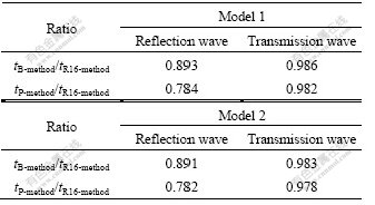
The above results indicate apparently that the method in this work can improve the calculation speed of ray-tracing. Meanwhile, the data in Table 1 show that the relative speed of tracing reflection wave ray path is apparently increased. This is probably because with the increase of the point of intersection of ray path and interface in the circumstance of reflection wave, the order of matrix equation will increase, and the relative calculation speeds will be improved.
5 DiscussionRay-tracing is the base of seismic tomography and seismic prestack depth migration. The speed and precision of ray-tracing influence on the effects of seismic tomography and prestack depth migration directly.
The whole-path ray-tracing method in 3D structure in Ref.[17] was realized by repeatedly solving systems of symmetry block positive definite tridiagonal equations. Regularly, these systems of linear equations set are regarded banded linear equations and solved by using the solution to the systems of banded linear equations directly. In this work, considering the property of symmetry positive definiteness of this matrix and keeping the advantage of band state of Cholesky decomposition method, the symmetry block positive definite tridiagonal matrix can be decomposed into the product of block bidiagonal triangular matrix and its transpose. It is not necessary to treat with the zero elements out of strip band. Furthermore, the speed of ray-tracing is enhanced.
In the same geological model, simulation calculations show that the ratio of computer CUP time cost in the procedure of the ray-tracing for reflection wave is less then that for transmission wave. This implies that, with the increment of the layers (point of intersection of ray path across interfaces), the relative speed for ray-tracing is enhanced, which reveals that the method presented in this research has the advantage in the circumstance of multilayer interface model.
6 Conclusions
1) Using the method of whole path-iterative ray- tracing and according to the positive definiteness of the coefficient matrix, an algorithm for solving the systems of symmetry block tridiagonal equations is deduced by means of Cholesky decomposition. It is not necessary to treat with the zero elements out of banded systems. This algorithm reduces the cost of the calculation time during the period of solving the systems of linear equations and quickens the speed of ray-tracing computation.
2) Simulation calculations indicate that the ratio of computer CPU time-cost of the method in this work is less than 1 in the process of ray-tracing, demonstrating that its relative speed is apparently higher than those in Ref.[16] and banded method.
3) The algorithm in this work is suitable for ray-tracing in multiple layered media, which is a kind of fast and practical ray-tracing method.
References[1] AKI K, CHRISTOFFERSSON A, HUSEBYE E S. Determination of the three-dimensional seismic structure of the lithosphere [J]. J Geophys Res, 1977, 82(2): 277-296.
[2] DUVENECK E. 3D tomographic velocity model estimation with kinematic wavefield attributes [J]. Geophysical Prospecting, 2004, 52(6): 535-545.
[3] IVANSSON S. Seismic borehole tomography theory and computational methods [J]. Proc IEEE, 1986, 74(2): 328-338.
[4] SCHUSTER G T. Fermat��s interferometric principle for target- oriented traveltime tomography [J]. Geophysics, 2005, 70(4): U47-50.
[5] YANG Zhuo-xin, ZHANG Xian-kang, YANG Jian, ZHAO Jin-ren. Joint inversion of 3-D crustal structure and velocity distribution [J]. Geophysical Progress, 1997, 12(1): 41-52. (in Chinese)
[6] ZHANG Zhong-jie, QIN Yi-long, CHEN Yun, ZHANG Chao-ying, SUN Shan-xue, ZHAO Bing, LIU Yi-feng, LIU Zhen-kuan. Reconstruction of the semblance section for the crust and mantle reflection structure by wide-angle reflection seismic data [J]. Chinese J Geophys, 2004, 47(3): 469-474. (in Chinese)
[7] ZHANG Zhong-jie, TENG Ji-wen, ZHANG Lin-bin, YANG Ding-hui. The modified Snell law for seismic ray in anisotropic media [J]. Chinese Science Bulletin, 1995, 40(20): 1724-1728.
[8] XU Tao, XU Guo-ming, GAO Er-gen, ZHU Liang-bao, JIANG Xian-yi. Block modeling and shooting ray in complex 3-D media [J]. Chinese J Geophys, 2004, 47(3): 1118-1126. (in Chinese)
[9] XU Tao, XU Guo-ming, GAO Er-gen, LI Ying-chun, JIANG Xian-yi, LUO Kai-yun. Block modeling and segmentally iterative ray tracing in complex 3D media [J]. Geophysics, 2006, 71(3): T41-51.
[10] XU Tao, XU Guo-ming, GAO Er-gen, JIANG Xian-yi. Refraction ray-tracing in complex medium [J]. Oil Geophysical Prospecting, 2004, 39(6): 690-693.
[11] XU Tao, XU Guo-Ming, GAO Er-Gen, JIANG Xian-yi, LUO Kai-yun. 3-D shooting ray-tracing sub-triangle method [J]. Oil Geophysical Prospecting, 2005, 40(4): 391-399.
[12] GJYSTDAL H, IVERSEN E, LECOMTE I, KASCHWICH T, DROTTNING A, MISPEL J. Improved applicability of ray tracing in seismic acquisition, imaging, and interpretation [J]. Geophysics, 2007, 72(5): SM261-271.
[13] BUSKE S, K?STNER U. Efficient and accurate computation of seismic traveltimes and amplitudes [J]. Geophysical Prospecting, 2004, 52(4): 313-322.
[14] GAO Er-gen, XU Guo-ming, LI Guang-pin, ZHAO Yi, TU Shi-jie. A new total iterative ray-tracing method in random interface [J]. Acta Custica, 2002, 27(3): 282-287. (in Chinese)
[15] ZHOU Zhu-sheng, ZHANG Sai-min, CHEN Ling-jun. Seismic ray-tracing calculation based on parabolic travel-time interpolation [J]. J Cent South Univ Technol, 2004, 11(2): 199-205.
[16] GAO Er-gen, XU Guo-ming, JIANG Xian-yi, LUO Kai-yun, LIU Tong-qing, XIE Duan, SHI Jin-liang. Iterative ray-tracing method segment by segment under 3-D construction [J]. Oil Geophysical Prospecting, 2002, 37(1): 11-16. (in Chinese)
[17] GAO Er-gen, Uk Han, TEN Ji-wen. Fast ray-tracing method in 3-D structure and its proof of positive definiteness [J]. J Cent South Univ Technol, 2007, 14(1): 100-103.
[18] GOLUB G H, van LOAN C F. Matrix computation [M]. Baltimore: Johns Hopkins University Press, 1983.
Foundation item: Project(40674071) supported by the National Natural Science Foundation of China; Project(KFAS2002-2003) supported by the Korea Foundation for Advanced Studies
Received date: 2008-01-30; Accepted date: 2008-05-21
Corresponding author: GAO Er-gen, Associate Professor, PhD; Tel: +86-551-3606871; E-mail: grg@ustc.edu.cn
(Edited by CHEN Wei-ping)
Abstract: Beginning with the method of whole path iterative ray-tracing and according to the positive definiteness of the coefficient matrix of the systems of linear equations, a symmetry block tridiagonal matrix was decomposed into the product of block bidiagonal triangular matrix and its transpose by means of Cholesky decomposition. Then an algorithm for solving systems of block bidiagonal triangular linear equations was given, which is not necessary to treat with the zero elements out of banded systems. A fast algorithm for solving the systems of symmetry block tridiagonal linear equations was deduced, which can quicken the speed of ray-tracing. Finally, the simulation based on this algorithm for ray-tracing in three dimensional media was carried out. Meanwhile, the segmentally-iterative ray-tracing method and banded method for solving the systems of block tridiagonal linear equations were compared in the same model mentioned above. The convergence condition was assumed that the L-2 norm summation for mk, 1 and mk, 2 in the whole ray path was limited in 10-6. And the calculating speeds of these methods were compared. The results show that the calculating speed of this algorithm is faster than that of conventional method and the calculated results are accurate enough. In addition, its precision can be controlled according to the requirement of ray-tracing.
