
J. Cent. South Univ. (2017) 24: 2306-2313
DOI: https://doi.org/10.1007/s11771-017-3642-2

Rock fragmentation under different installation polar angles of TBM disc cutters
CHENG Yong-liang(������)1, 2, ZHONG Jue(�Ӿ�)1, MEI Yong-bing(÷�±�)1, 2, XIA Yi-min(������)1
1. State Key Laboratory of High Performance Complex Manufacturing, Central South University,Changsha 410083, China;
2. China Railway Construction Heavy Industry Co., Ltd., Changsha 410100, China
 Central South University Press and Springer-Verlag GmbH Germany 2017
Abstract:
The disc cutters of tunnel boring machine (TBM) are installed with different polar angles. This causes the cutting depth difference between adjacent disc cutters on the tunnel face. A rock-cutting model was established to study the rock fragmentation law between adjacent disc cutters with different polar angles based on particle flow code (PFC). The influence of polar angle of adjacent disc cutters on rock cracks and stresses under different cutter spacing and penetration was studied. Research shows that polar angle difference leads to the discontinuity of rock-fragmentation process by adjacent cutters. The effect of rock-fragmentation is influenced by the cutting depth difference between adjacent cutters. The effect of rock-fragmentation performed best, meanwhile large rock blocks were flaked when the difference of cutting depth is half of the penetration. Too large or small difference of the cutting depth will cause high specific energy consumption of rock fragmentation. The specific energy consumption is relatively small when the difference of cutting depth is half of the penetration.
Key words:
tunnel boring machine; disc cutter; polar angle; particle flow code; rock fragmentation��
1 Introduction
Tunnel boring machine (TBM) occupies a very important role in tunnel construction projects nowadays. TBM moves forward by disc cutters of cutter-head rolling and breaks the rock [1�C5]. Construction quality is influenced directly by fragmentation of tunnel face. Many studies have been presented on rock crack formation and propagation patterns under the action of disc cutter. The crush zone is generated beneath the disc cutter, and then the intermediate cracks, radial cracks and lateral cracks develop outwards from the disc cutter [6]. LIU et al [7, 8] and SU et al [9] simulated the formation and development of rock cracks under the action of TBM cutter and pointed out that the effect of rock fragmentation was determined by the law of rock cracks�� development. The growth of rock cracks under the action of disc cutter is influenced by geological factors including rock strength, rock internal structure, mineral content, joints and confining stress [10]. Two- dimensional numerical study was applied by TAN et al [11] to explore the influence of joint strength, spacing and orientation on rock fragmentation. LIU et al [12] adopted a 2D discrete element method to explore the effects of embedded cracks with different dip angles on the rock fragmentation process, cutting characteristics and breaking efficiency. Combined with numerical simulation, the influence of confining stress on cutting process, fracture conditions and cutting efficiency of soft and hard rock has been conducted on the triaxial testing machine by MA et al [13] and LIU et al [14]. TBM cutter-head and its tunnelling parameters are set up reasonably according to the geological conditions in a construction project. Among those parameters, disc cutter spacing and cutter-head penetration have a great influence on rock fragmentation effect.
BALCI [15] studied the effect of disc cutter penetration and specific energy consumption by using the linear cutting test. Based on the principle of minimum specific energy consumption, the appropriate cutter spacing and penetration were selected and the feasibility was verified by comparing with the actual engineering data, which guided the selection of TBM parameters. CHO et al [16] made a simulation of the linear cutting machine test (LCM) by using AUTODYN-3D. The rock fragmentation process was analyzed and the optimum cutting spacing was acquired based on the principle of the minimum specific energy consumption.
TAN et al [17] used the discrete element method to analyze the dynamic response mechanism and rock crack propagation law under the action of double disc cutters. The optimum disc cutter spacing was acquired and the simulation was verified on the rotary cutting test machine. The position layout of TBM disc cutter is usually represented by its installation radius and the polar angle on the cutter-head. The influence of disc cutter��s installation polar angle on rock fragmentation was not considered in the above stated researches. The order of cutting is influenced by installation polar angle. MOON and OH [18] simulated the process of disc cutter sequentially pressing into the rock with different penetrations and cutter spacing based on the discrete element software and verified the result with linear cutting machine test. TAN et al [19] also simulated and studied different rock fragmentation models of disc cutter cutting simultaneously or sequentially based on the discrete element numerical simulation. HUO et al [20] established a mapping relationship between sequential angle and rock fragmentation energy under optimum cutter spacing of multiple disc cutters, and pointed out that the rock fragmentation efficiency is higher with multiple disc cutters sequentially breaking the rock.
The installation polar angle of disc cutter not only affects the cutting sequence, but also leads to crack interaction in the circumferential direction and cutting depth��s difference in the direction of tunnelling. This work aims to investigate the effect of different polar angles of adjacent disc cutters and different interaction models of adjacent disc cutters on TBM cutter-head. Using discrete element simulation software, the process of crack growth and rock fragmentation effect under different cutting depths were analyzed.
2 Rock fragmentation methods of disc cutters with different polar angles
2.1 Cutting depth between adjacent disc cutters
The whole TBM disc cutter rotates in a spiral form. On the one hand, it moves in a uniform circular shape along the cutter-head. On the other hand, it moves forward with the same speed in the direction of tunnelling. The position of TBM disc cutter on the cutter- head is usually determined by its installation radius and the polar angle. As shown in Fig. 1, adjacent disc cutters are often arranged in different polar angles. The adjacent disc cutters pass by one region with a time difference when cutter-head rotates to cut rocks. It means that when the adjacent disc cutters pass by any radial line sequentially, there will be some cutting depth differences between the previous and the next cutter on this radial line. As shown in Fig. 2, because rocks are flaked unevenly in rock-breaking process, the tunnelling face is often uneven when TBM disc cutters break the rock. Cutting depth difference of adjacent disc cutters aggravates the unevenness of tunnelling face.

Fig. 1 8 m open type TBM cutter-head
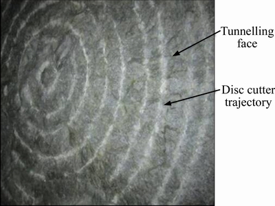
Fig. 2 Tunnel face of Liaoning northwest water diversion project
The polar angle difference between two adjacent cutters is denoted as �� (�ȡܦ�), and the cutter-head tunnels forward for h with one revolution. Then there will be two cases on adjacent disc cutters�� cutting depth in one rotation:
 (1)
(1)
There might be three rock fragmentation forms between adjacent cutters in the process of one rotation.1) Cutting depth difference h1 and h2 appears alternately; 2) Rock is broken only with cutting depth h1; 3) Rock is broken only with cutting depth h2. If the cutter cannot break the rock with cutting depth h1, it will break the rock with the cutting depth h2 later. In the following, the result of rock cutting in some cutting depth will be studied and the effects of rock fragmentation with different cutting depth are compared.
As shown in Fig. 3(a), the cutter-head rotates in a counter clockwise direction and the polar angle difference between the inside disc cutter and the outside disc cutter is ��/6. In zone A, the outside cutter cuts the rock ahead of the inside one by ��/6 and the inside cutter is h/12 lower in depth than the outside one. In zone B, the inside disc cutter cuts the inside rock along the arc LN. When the outside disc cutter rolls in zone B, it has fallen behind the inside disc cutter by 5��/6 and the outside cutting depth is smaller than the inside one by 11h/12. In one rotating process of cutter-head, if h1 and h2 appear alternately, the proportion of the area of the rock fragmentation will be  (A1 and A2 represent the area of zone A and zone B respectively), which means that there will be a bigger area of rock fragmentation when the cutting depth difference is smaller. When the polar angle is smaller, although h1 and h2 vary greatly, the rock fragmentation face is relatively flat with a smaller cutting depth difference in most part of the area.
2.2 Discontinuous rock fragmentation process
TBM breaks the rock by the crack interaction produced by adjacent disc cutters. The existence of the polar angle difference between adjacent disc cutters determines that there is not always crack interaction between adjacent disc cutters, and the process of rock fragmentation is discontinuous. As still shown in Fig. 3(a), when the inside disc cutter is in zone B and the outside disc cutter is in zone A, the cracks produced by adjacent disc cutters do not interact and the effect of rock fragmentation is not obvious. When the inside disc cutter is in zone A or the outside disc cutter is in zone B, the cracks produced by adjacent disc cutters interact and large rocks peel. In one rotation of the cutter-head, interaction time between adjacent disc cutters is t2 and non-interaction time is t1, then:
 (2)
(2)
This shows that non-interaction time t1 is longer and the discontinuity of the process of rock fragmentation is more obvious while the polar angle difference is bigger. Figure 3(b) is shows a schematic view of the rock fragmentation process when the polar angle difference between the inside and the outside disc cutters is ��. During the first half of the cutter-head��s one rotation, the outside disc cutter rolls along the arc ML and the inside disc cutter rolls along the arc HN, and there is no collaborative rock-breaking between the inside and outside cutters. During the second half of the cutter-head��s one rotation, Inner and outer cracks intersect, which resulted in that two disc cutters broke the rock collaboratively. The cutting depth of the inside cutter is lower than the outside one by h/2 in zone A, and higher by h/2 in zone B.
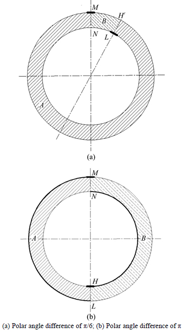
Fig. 3 Sketch of rock cutting process by adjacent cutters:
During the first half of the cutter-head��s one rotation, there is not much rock peeling off between adjacent disc cutters, therefore rock fragmentation by adjacent disc cutters is mainly in the second half of the rotation. This is an alternate rock fragmentation process. The discontinuity of rock fragmentation process exacerbates the cutter-head vibration and load instability.
3 Rock fragmentation effect of disc cutters with different polar angle
3.1 Establishment of rock-breaking model by disc cutter
Rock will act in diverse crushing patterns under different cutting depth difference of adjacent disc cutters. With discrete element simulation software, the effect of rock-breaking under different cutting depths is simulated, and the model of rock-breaking by disc cutter is established as shown in Fig. 4. The rock samples are made of a large number of flexibly-glued rigid particles. Contact failures are classified into tensile failure and shear failure, which are respectively shown in red and blue (Fig. 5). The macroscopic parameters of marble are shown in Table 1. The size of the rectangular model is 400 mm in length and 120 mm in height. According to the cutting depth difference, some part of the rock is ignored and the ramp boundary is applied between two cutters. The cutters are regarded as rigid bodies, which are pressed into the rock samples sequentially. The right cutter is pressed into the rock with a depth of h firstly, and then the left cutter is also pressed into the rock with a depth of h which is lower than the right cutter by ��h.

Fig. 4 Schematic diagram of simulation model
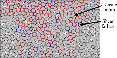
Fig. 5 Discrete element of rock particles
3.2 Process of crack development with cutting depth differences
The cases that cutter spacing is 80 mm and 90 mm respectively and the penetration is 8 mm were selected. The processes and effects of rock-fragmentation at varying cutting depth differences were compared.
As shown in Fig. 6(a), two adjacent disc cutters were pressed into the rock at the same cutting depth. Shear cracks and tensile cracks generated where the cutter and the rock contacted with each other and the crush zone generated under the cutters. With the cutter intruding into the rock continuously, intermedian and lateral cracks were generated around the crush zone. Intermedian cracks continued to develop to a greater depth, while lateral cracks developed along the direction which is approximately parallel to the free face until the lateral cracks generated from adjacent cutters intersected and rocks flaked. Then the process of rock-fragmentation was completed. Due to the anisotropy of the rock, the fragmentation conditions near adjacent cutters were not all the same.
When there was a polar angle between adjacent cutters, two cutters could not go through any cross section simultaneously and there was a sequence. The latter cutter had a larger cutting depth. Figure 6(b) shows the rock-fragmentation situation at a cutting depth��s difference of 4 mm. Due to the influence of left lateral ramp, the limiting effect to cutter cracks was less comparing to a plane case, and left lateral cracks were fully developed and extended further when the first cutter was pressed into the rock as shown in Fig. 6. The cutter load undertaken by the dense core is unloaded by both the intermediate cracks and the lateral cracks. In Fig. 6(a), the left lateral cracks developed greater which caused the right lateral cracks were relatively short. When the second disc cutter intruded into the rock, lateral cracks intersected with the ones generated by the first disc cutter and the rock-flaking was formed. The effect of rock-fragmentation was relatively fine in this case. As the second cutter��s lateral cracks formed rock block too early, the disc cutter��s load accumulated later was released through dense core, intermediate cracks and left lateral cracks. The left lateral cracks extended to the free surface and rock blocks were formed. The block is a little bigger than that in Fig. 6(a).
Figure 6(c) shows the cracks propagation at the cutting depth difference of 7 mm. Due to the increase of cutting depth difference, the slant angle between two cutters became larger and the limiting effect on the first cutter��s lateral cracks became smaller. When the first cutter intruded into the rock, the disc cutter��s left lateral cracks intersected with free surface too early, which resulted in its incomplete development. The nearby rocks were fragmented excessively, while the right lateral cracks were developed fully. Then, the second disc cutter intruded into the rock. The lateral cracks developed along the direction parallel to the inclined plane and eventually intersected with the first area of rock- fragmentation and the rock blocks were formed. However, the block was relatively smaller and flaked in slices, compared with that in Fig. 6(b).
The effect of rock-fragmentation was simulated at the cutter spacing of 90 mm as well. Similar results were obtained. As shown in Figs. 7(a)�C(d), the cutting depth difference is respectively 0, 2, 4 and 6 mm. When the cutting depth difference is 0, lateral cracks between two cutters did not intersect. With the cutting depth difference increasing to 2 mm and 4 mm, the cracks intersected and big rock blocks flaked. With the cutting depth difference increasing to 6 mm, the flaked rocks became thin and were peeled off in slices.
Table 1 Macroscopic parameters of rock

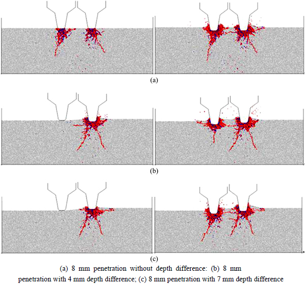
Fig. 6 Development of rock cracks under different cutting depths:
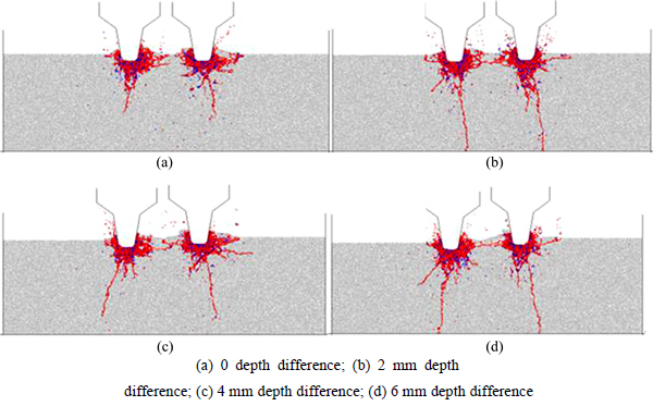
Fig. 7 Rock-breaking effect under different cutter depths with 90 mm cutter spacing:
3.3 Results and discussion
3.3.1 Stress and crack
Rock crack propagation is closely related to the internal stress distribution of rock. If the tensile stress exceeds the tensile strength, there will be tensile cracks. If the shear stress exceeds the shear strength, there will be shear cracks. Different cutting depth differences result in the appearance of different stress boundaries and the internal stress distribution will change along with it. Because of the complexity of rock-fragmentation machanism, rock failure cannot be judged by a single failure criterion. Therefore rock failure cannot be judged by a single stress situation. In this work, the principal stress distribution is used for comparison and analysis. Figure 8(a) shows the stress distribution and crack development when the two cutters intruded the rock simultaneously. The blue region is the compressive stress area, and the yellow region is the tensile stress area. The stress beneath the cutter was great because of the extruding of cutter and the limiting of surrounding rocks. Shear cracks were generated in part of the rocks indicating plastic deformation in some area. The crush zone was formed under the action of shear cracks and tensile cracks simultaneously. With the stress spreading around, stress value and the number of cracks decreased gradually. Due to the existence of tensile stress area, tensile cracks moved closer to its direction and the intermediate cracks were formed. Figure 8(b) shows the stress and cracks distribution state of the first cutter intruding the rock when there is a cutting depth difference. The stress of the dense core area under the disc cutter is great. This area is the coexistence region of tensile cracks and shear cracks. Extending from dense core to the surrounding, the tensile cracks spread to the tensile stress area, and then the long cracks were formed. Because of the inclined surface, the lateral cracks more easily extended to the free surface. The early development state of cracks had great influence on the later rock fragmentation. So the different boundary conditions, which were resulted from the cutting depth difference between adjacent cutters, lead to different effect of rock-fragmentation.
3.3.2 Disc-cutter load
Two-dimensional simulation of cutter load is different from three-dimensional simulation and the results are not comparable. However, the variation of cutter load can be compared qualitatively by comparing the two-dimensional loads. Figure 9 shows the variation of cutter load and cracks when the disc cutter intruded the rock, which presented step properties obviously. During the early time of cutter intruding the rocks, cutter load increased continuously and the number of cracks increased rapidly. It reached the initial maximum force at point P then decreased and fluctuated, and the growth rate of crack number slowed down. Figure 10 shows the variation of cutter load along with the different cutting depth between adjacent cutters at the cutter spacing of 80 mm. A great number of cracks generated when the first cutter intruded reduced the intruding force reasonably for the latter cutter; therefore the latter cutter��s maximum force is generally smaller than the first cutter. The increase of cutting depth difference changed the boundary conditions which resulted in slight decrease of the first cutter��s initial maximum force, while the change for latter cutter was little. Average load of the first and the later cutter did not have obvious change along with the change of cutting depth difference, and there was no obvious difference between the two loads.The existence of cutting depth difference had great influence on the initial stress state. With the cutter intruding into the rock, many cracks were generated and the effect of initial boundary conditions on loads was weakened. Therefore, the initial maximum cutter load was different, but there was not obvious difference between the overall average loads of disc cutters.
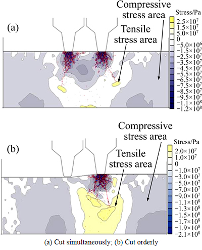
Fig. 8 Distribution of rock stress and crack development:
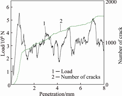
Fig. 9 Variation characteristics between cutter load and number of rock cracks
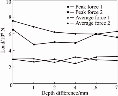
Fig. 10 Comparison between cutting depth difference and cutter load
3.3.3 Area of flaked rock and specific energy consumption
Flaked rocks mainly included the rocks in the excessive fragmentation area near the cutter, flaked rocks between the two disc cutters and small rocks flaked from one side of the disc cutter. Flaked rocks between the two disc cutters were formed from intersection of lateral cracks under adjacent cutters, and its area can reflect the collaborative rock-fragmentation effect of adjacent cutters and was very important for the tunnelling efficiency of TBM and the amount of energy consumption. Figure 11 shows the comparison of different areas of intermediate flaked rock at varying cutting depth difference. By comparing the area of rock-fragmentation, it is found that the maximum area of rock-fragmentation at the cutter spacing of 80 mm and 90 mm appeared when the cutting depth difference between adjacent cutters was 4 mm. The area of rock- fragmentation became smaller whenever the cutting depth was larger or smaller. Overall, the area of rock-fragmentation at cutter spacing of 90 mm was larger than that of 80 mm, but the cracks did not intersect when the cutter spacing was 90 mm and there was no cutting depth difference. So there was not any flaked rock in the middle.
Figure 12 shows comparison of specific energy consumption at varying cutting depth difference. When the cutting depth difference was small, cracks of rocks intersected at a cutter spacing of 90 mm and specific energy consumption was high. With cutting depth difference increasing, rock-fragmentation specific energy consumption gradually reduced after the cracks intersected. The specific energy consumption reached the minimum at 4 mm. As the cutting depth difference increases, the specific energy consumption increased gradually. With the cutter spacing of 80 mm, the specific energy consumption presented a similar law of variation. When the cutting depth difference was small, the rock cracks intersected and its specific energy consumption was lower compared with that at 90 mm cutter spacing. The specific energy consumption also reached the lowest at 4 mm. However, its value was higher than that with 90 mm cutter spacing. Intermediate rock fragmentation was greatly relevant to specific energy consumption of the overall rock-fragmentation. The lateral cracks may not intersect when the cutting depth difference was too small. While the cutting depth difference was too big, rock flaked in slices and the specific energy consumption of rock-fragmentation was high. When cutting depth was 1/2 of penetration, intermediate flaked rock was large and its specific energy consumption was low.
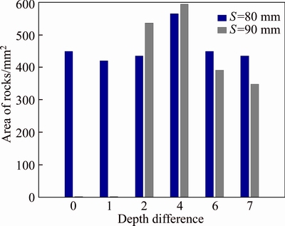
Fig. 11 Statistics of intermediate flaked rock under different depths
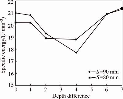
Fig. 12 Comparison of specific energy consumption under different cutting depths
4 Conclusions
1) Adjacent cutters break the rock with a certain different cutting depth. In the process of cutter-head��s one rotation, there are two kinds of cutting depths which is determined by the polar angle and penetration between adjacent cutters.
2) The difference of polar angle leads to the discontinuity of rock-fragmentation process of adjacent cutters. Only part of the cutter-head��s one rotation is the process of collaborative rock-fragmentation. When the difference of polar angle is 180��, the process of rock-fragmentation discontinuity is the most significant. Half of the rotation is the process of rock cutting by a single disc cutter alone. Another half is the process of collaborative rock-fragmentation, resulting in large rock flakes.
3) The difference of cutting depth between adjacent cutters influences the effect of rock-fragmentation. The effect of rock-fragmentation is the best when the difference of cutting depth is 1/2 of the penetration and there are large rock blocks flaked. When the cutting depth difference is too small, lateral cracks develop incompletely and the cracks can not intersect if the cutter spacing is large; when the cutting depth difference gets larger, rocks flake in slices and the area of flake decreases.
4) Too large or small difference of the cutting depth will cause high specific energy consumption of rock fragmentation. The specific energy consumption will be relatively small when the difference of cutting depth is half of the penetration. Besides, increasing the cutter spacing will decrease the specific energy consumption.
References
[1] XIA Yi-min, OUYANG Tao, ZHANG Xin-ming, LUO De-zhi. Mechanical model of breaking rock and force characteristic of disc cutter[J]. Journal of Central South University of Technology, 2012, 19(7): 1846�C1852.
[2] GONG Q M, ZHAO J. Influence of rock brittleness on TBM penetration rate in Singapore granite [J]. Tunnelling and Underground Space Technology, 2007, 22(3): 317�C324.
[3] WANG Li-hui, KANG Yi-lan. The energy method to predict disc cutter wear extent for hard rock TBMs [J]. Tunnelling and Underground Space Technology, 2011, 28: 183�C191.
[4] TUNCDEMIR H, BILGIN N, COPUR H, BALCIC. Control of rock cutting efficiency by muck size [J]. International Journal of Rock Mechanics and Mining Sciences, 2008, 45(2): 278�C288.
[5] ROSTAMI J. Study of pressure distribution within the crushed zone in the contact area between rock and disc cutters [J]. International Journal of Rock Mechanics and Mining Sciences, 2013, 57: 172�C186.
[6] KOU S Q, HUANG Y, TAN X C, LINDQVIST P A. Identification of the governing parameters related to rock indentation depth by using similarity analysis [J]. Engineering Geology, 1998, 49(3): 261�C269.
[7] LIU H Y, KOU S Q, LINDPVIST P A, TANG C A. Numerical modelling of the heterogeneous rock fracture process using various test techniques [J]. Rock Mechanics and Rock Engineering, 2007, 40(2): 107�C144.
[8] LIU H Y, KOU S Q, LINDPVIST P A, TANG C A. Numerical simulation of the rock fragmentation process induced by indenters [J]. International Journal of Rock Mechanics and Mining Sciences, 2002, 39(4): 491�C505.
[9] SU L J, SUN J S, LU W B. Research on numerical simulation of rock fragmentation by TBM cutters using particle flow method [J]. Rock and Soil Mechanics, 2009, 30(9): 2823�C2829. (in Chinese)
[10] BALCI C, TUMAC D. Investigation into the effects of different rocks on rock cuttability by a V-type disc cutter [J]. Tunnelling and Underground Space Technology, 2012, 30: 183�C193.
[11] TAN Qing, ZHU Yi, XIA Yi-min, XU Zi-jun, LI Jian-fang, SONG Jun-hua. Influence of joint characteristics on rock fragmentation induced by TBM disc cutter [J]. Journal of Central South University of Technology: Science and Technology, 2013, 44(10): 4040�C4046. (in Chinese)
[12] LIU Jie, CAO Ping, JIANG Zhe, ZHAO Yan-lin, CAO Ri-hong. Numerical simulation on effects of embedded crack on rock fragmentation by a tunnel boring machine cutter [J]. Journal of Central South University, 2014, 21(8): 3302�C3308.
[13] MA H S, YIN L J, JI H G. Numerical study of the effect of confining spacing stress on rock fragmentation by TBM cutters [J]. International Journal of Rock Mechanics & Mining Sciences, 2011, 48(6): 1021�C1033.
[14] LIU Jing-shuo, CAO Ping, LIU Jie, JIANG Zhe. Influence of confining stress on fracture characteristics and efficiency of TBM cutters conducted on soft and hard rock [J]. Journal of Central South University, 2015, 22(5): 1947�C1955.
[15] BALCI C. Correlation of rock cutting tests with field performance of a TBM in a highly fractured rock formation: A case study in Kozyatagi-Kadikoy metro tunnel [J]. Tunnelling and Underground Space Technology, 2009, 24(4): 423�C435.
[16] CHO J W, JEON S, YU S H, CHANG S H. Optimum spacing of TBM disc cutters: A numerical simulation using the three-dimensional dynamic fracturing method [J]. Tunnelling and Underground Space Technology, 2010, 25(3): 230�C244.
[17] TAN Qing, YI Nian-en, XIA Yi-min, XU Zhi-jun, ZHU Yi, SONG Jun-hua. Research on rock dynamic fragmentation characteristics by TBM cutters and cutter spacing optimization [J]. Chinese Journal of Rock Mechanics and Engineering, 2012, 31(12): 2453�C2464. (in Chinese)
[18] MOON T, OH J. A study of optimal rock-cutting conditions for hard rock TBM using the discrete element method [J]. Rock Mechanics and Rock Engineering, 2012, 45(5): 837�C849.
[19] TAN Qing, XU Zi-jun, XIA Yi-min, ZHANG Kui. Numerical study on mode of breaking rock by TBM cutter in two cutting orders [J]. Journal of Central South University: Science and Technology, 2012, 43(3): 940�C946. (in Chinese)
[20] HUO Jun-zhou, SUN Wei, GUO Li, LI Zhen, ZHANG Xu. Numerical simulation of the rock fracture process induced by multi-disc-cutters and cutter spacing design [J]. Journal of Harbin Engineering University, 2012, 33(1): 96�C99. (in Chinese)
(Edited by HE Yun-bin)
Cite this article as:
CHENG Yong-liang, ZHONG Jue, MEI Yong-bing, XIA Yi-ming. Rock fragmentation under different installation polar angles of TBM disc cutters [J]. Journal of Central South University, 2017, 24(10): 2306�C2313.
DOI:https://dx.doi.org/https://doi.org/10.1007/s11771-017-3642-2Foundation item: Project(2012AA041801) supported by the Hi-tech Research and Development Program of China; Project(2013CB035401) supported by the National Basic Research Program of China; Project(51475478) supported by the National Natural Science Foundation of China
Received date: 2016-03-21; Accepted date: 2016-08-15
Corresponding author: CHENG Yong-liang, Senior Engineer; Tel: +86�C15873319850; E-mail: yongliangcheng@163.com
Abstract: The disc cutters of tunnel boring machine (TBM) are installed with different polar angles. This causes the cutting depth difference between adjacent disc cutters on the tunnel face. A rock-cutting model was established to study the rock fragmentation law between adjacent disc cutters with different polar angles based on particle flow code (PFC). The influence of polar angle of adjacent disc cutters on rock cracks and stresses under different cutter spacing and penetration was studied. Research shows that polar angle difference leads to the discontinuity of rock-fragmentation process by adjacent cutters. The effect of rock-fragmentation is influenced by the cutting depth difference between adjacent cutters. The effect of rock-fragmentation performed best, meanwhile large rock blocks were flaked when the difference of cutting depth is half of the penetration. Too large or small difference of the cutting depth will cause high specific energy consumption of rock fragmentation. The specific energy consumption is relatively small when the difference of cutting depth is half of the penetration.
