
J. Cent. South Univ. (2017) 24: 1612-1618
DOI: 10.1007/s11771-017-3566-x

CHENG Pan(����)1, ZHAO Lian-heng(������)2, ZHANG Shao-wei(����ΰ)1, LI Liang(����)2,
SHEN Zhi-qiang(��־ǿ)1, NING Peng-fei(������)1, ZHANG Ze-hai(����)1
1. Department of Civil Engineering, College of Basic Education, National University of Defense Technology, Changsha 410072, China;
 Central South University Press and Springer-Verlag Berlin Heidelberg 2017
Abstract:
To assess the water inflow which is more suitable to the actual conditions of tunnel, an empirical correlation about the permeability coefficient changing with depth is introduced. Supposing that the surrounding rock is heterogeneous isotropy, the formula for calculating water inflow of tunnel with the nonlinear variation of permeability coefficient is deduced. By the contrast analysis with the existing formulas, the presented method has the similar value to them; moreover, the presented method has more simple form and easy to use. Due to parameter analysis, the water inflow decreases after considering the nonlinear variation of permeability coefficient. When the attenuation coefficient a>0, the water inflow increases first till reaches the maximum at a certain depth, then decreases and is close to 0 finally if deep enough. Thus, it is better to keep away from the certain depth where it is with the maximum water inflow for safe operation and economical construction, and reduce the water damage. Based on the analysis, the radius of tunnel has less impact on the amount of water inflow, and the water inflow just increases by 6.7% when the radius of tunnel increases by 1 m.
Key words:
1 Introduction
Tunnel is always encountered in the construction of traffic project, especially at mountain areas in south of China. In general, tunnel is below the groundwater table and surrounded by groundwater during construction and after operation. If out of control, the groundwater may seep into the tunnel and lead to large amount of damages, such as water burst, ground floor collapse and destroy of ecological environment [1-3]. Meanwhile, huge time and economic consumption is needed to treat the damages. Therefore, it is essential to deal with the groundwater effectively.
However, only when the water inflow is determined exactly, the effective measurement can be established. Lots of scholars do some researches on the method for predicting water inflow all over the world [4-13], such as the formula of Goodman, Hirishi Oshima, Kuniaki Sato and the method which is recommend in the technical code for waterproofing and drainage of railway tunnel (TB10119��2000) [11, 14]. Nevertheless, all the methods mentioned above are based on the assumption that the rock mass is homogeneous isotropic, while the assumption is inconsistent with the reality. Thus, to calculate the amount of water inflow more exactly, the character of heterogeneity for surrounding rock is necessary to be considered.
Due to the analysis above, this work aims to establish a water inflow forecasting method according with site reality. Based on experience formula and numerical calculation method, the equation for calculating water inflow of tunnel is deduced with nonlinear variation of permeability coefficient into consideration. Then, the results of the proposed method were evaluated by comparing them with existent methods. Meanwhile, on the basis of parameter analysis, the influence factor of water inflow is discussed when considering the nonlinear variation of permeability coefficient.
2 Relationship between permeability coefficient and depth
Permeability coefficient is an extremely important parameter for determining the water inflow. The accurate evaluation of permeability coefficient makes the water inflow more accurate and realistic. Based on the investigation and analysis of the actual sites [1, 9, 15-23], the penetration coefficient often changes with depth. In general, the greater the depth, the smaller the permeability coefficient, and the difference may be several orders of magnitude.
ZHANG and FRANKLIN [1] cited a group of survey data which showed that the permeability coefficient reduced for 3 or 4 orders of magnitude at the depth of 40-60 m. At the depth of 10 m, the order of magnitude of permeability coefficient was 10-5, while at 60 m below the ground, the permeability coefficient reduced to magnitude of 10-8. Another set of data showed the same results that the magnitude of permeability coefficient at the depth of 10 m was 10-7, while at 40 m was reduced to 10-11, which indicated that the trend of permeability coefficient changing with depth was obvious.
The phenomenon that the permeability coefficient changed with depth is related to various factors. For instance, the stress of surrounded rock increases with the depth because the fracture narrows down and the permeability coefficient may decrease. Meanwhile, the larger the depth, the better the rock integrity, and the diminishing of pores and cracks leads to the reduction of permeability coefficient.
There are some empirical formulae to express the relationship between permeability coefficient and depth, and the most common and simple formula is the exponential model proposed by LOUIS [24] in 1974, which is on the basis of large number of field tests. The empirical formula is expressed as follows [24]:
 (1)
(1)
where k is the permeability coefficient at the depth D; ks is permeability coefficient at D=0; a is osmotic gradient coefficient (attenuation coefficient).
Through site test, LOUIS [24] measured the data of two dam foundations in France and got the attenuation coefficient a of foundation was 0.04 m-1 and 0.12 m-1, respectively. There were also some other tests for determining a. For example, the attenuation coefficient a for Canada slate was 0.27 m-1 with double-packer injection tests. Tests for the Northumberland Straits tunnel in mudstones and sandstones in the range of 30 m showed the decrease of permeability coefficient, and the a was 0.08 m-1 [1]. Based on statistics, TANI [9] obtained the relationship between permeability coefficient and the depth as shown in Table 1.
The generality that the permeability coefficient changes with depth can be seen from the analysis and date above, so considering permeability coefficient variation with depth is significance for water inflow calculation, and the exponential distribution is the most commonly used when considering permeability coefficient variation.
3 Water inflow calculation method considering nonlinear change of permeability coefficient
3.1 Assumptions
1) Groundwater table is horizontal and the section of tunnel is circular;
2) Surrounding rock of the tunnel is non- homogeneous isotropic, and the permeability coefficient changes with depth;
3) Groundwater seepage is radial flow and obeys Darcy��s law.
3.2 Theoretical derivation
The computing model is shown in Fig. 1. The distribution formula of groundwater head proposed by POLUBARINOVA-KOCHINA [25] is widely used in computing the groundwater seepage. The formula is shown as follows.
 (2)
(2)
where c is a constant; H is the distance from groundwater table to centerline of tunnel. On the tunnel circumference  r is radius of tunnel, Eq. (2) can be transformed to
 (3)
(3)
Table 1 Exponential distribution of exponential distribution for different areas [9]
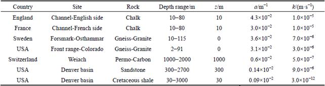
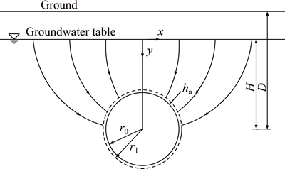
Fig. 1 Calculation model figure of groundwater inflow
Meanwhile, the tunnel circumference H-r��y��H+r can be converted to y=H-r+2��r with 0�ܦΡ�1. So, on the tunnel circumference, simplifying Eq. (3) yields:
 (4)
(4)
for deep tunnel, H>>r, we have
 (5)
(5)
Supposing that there is a circle which is adjacent to the tunnel circumference with the radius r1, the expression of groundwater head at r1 is
 (6)
(6)
From Darcy��s law,
 (7)
(7)
where V is permeate rate; K is permeability coefficient; J is hydraulic gradient. For r0 to r1 section,
 (8)
(8)
So,
 (9)
(9)
Since the permeability coefficient changes with depth, as shown in Fig. 2, for the tunnel circumference the permeability coefficient k can be expressed as
 (10)
(10)
Combine Eq. (1), Eq. (7), Eq. (9), and Eq. (10), the radial velocity v of groundwater inflow at tunnel circumference can be acquired.
 (11)
(11)
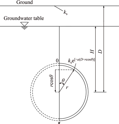
Fig. 2 Calculation diagram of water inflow with permeability coefficient changing over depth into consideration
The value of water inflow q for unit time and unit length is given by
 (12)
(12)
where s is the distance of permeation. Because the tunnel is symmetrical, taking the right semicircle into consideration, substituting Eq. (11) to Eq. (12) and solving it with integral transformation, water inflow q can be described as

 (13)
(13)
Hence,
 (14)
(14)
Take Eq. (14) into Eq. (5), the groundwater head at tunnel circumference is obtained:
 (15)
(15)
Convert to
 (16)
(16)
Equation (16) is the formula to calculate the water inflow considering the permeability coefficient variation.
When ignoring the change of permeability coefficient, a equals zero. Meanwhile, for road and railway tunnels, there is no internal pressure. So, the water pressure on the lining is 0, namely, ha=0, then Eq. (16) simplifies to Eq. (17) which is in accordance with the empirical formula proposed by GOODMAN.
 (17)
(17)
4 Comparison with ZHANG method and TANI method
Different parameters were taken to contrastively analyze the results between the method presented in this article and the other two formulas proposed by ZHANG and FRANKLIN [1] and TANI [9]. Assume that the permeability ks is measured at the groundwater table, where H=D, and there is no inside pressure on lining, namely, ha=0. a has been assigned the values 0, 0.0001, and 0.001. r was valued as 3 m and 9 m. The depth h ranged from r to 1000 m. The results are calculated as follows.
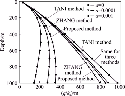
Fig. 3 Contrastive analysis of water inflow at r=3
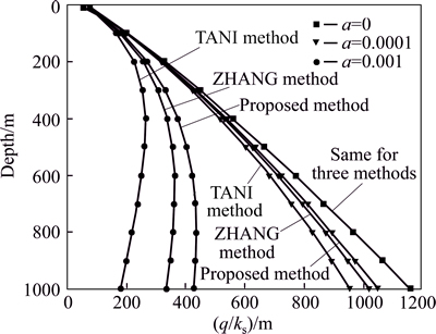
Fig. 4 Contrastive analysis of water inflow at r=9 m
From Figs. 3 and 4, it can be seen that the water inflow for three methods is almost the same when a=0. That is, regardless of the permeability coefficient changing with depth the three methods can better mutual verify.
For a>0, namely, considering permeability changing with depth, there are a little gap among these three methods. For the same attenuation coefficient a and at the same depth, the value calculated by the proposed method is the max, while ZHANG method is the middle and TANI method is the minimum. However, these three values are close to each other. In addition, the gap of the values among the three methods raises first, then decreases and approaches zero finally with the depth increasing.
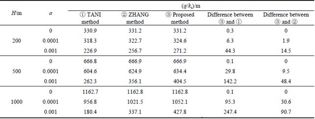
Generally speaking, the depth for traffic tunnel was less than 500 m. From Tables 2 and 3, when groundwater head is 500 m, the largest gap between �� and �� is just 48.4 m. If consider ks=0.1 m/d, the water inflow q just equals 4.8 m3/(m-1��d-1). However, 0.1 m/d is a quite large permeability coefficient in rock. Therefore, the smaller the permeability coefficient, the less the gap. Compared to ZHANG and TANI methods, the value of the proposed method is a little higher, which provides a safety coefficient and is more secure for engineering. Most of all, the presented equation is simple and easy to calculate by numerical method, which is convenient to utilize.
Table 2 Compared calculation table of water inflow at r=3 m
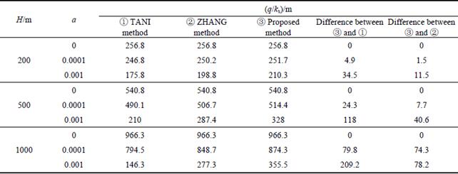
Table 3 Compared calculation table of water inflow at r=9 m
5 Parameter analysis
Different parameters are taken for analysis. Assume that the permeability ks is measured at groundwater table, that is H=D, and no internal water pressure on lining, that is ha=0, a equals 0, 0.0001, 0.0005, 0.001 m-1, r equals 2 m and 8 m, the depth h equals r-1000 m. The results are as follows.
Figures 5 and 6 show the water inflow (expressed by q/ks) changing with depth, radius of tunnel and attenuation coefficient a.
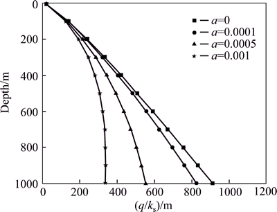
Fig. 5 Variation of q/ks changing with depth and a at r=2 m
It can be concluded from the figures as follows.
1) When a=0, the water inflow monotonically increased with depth. But for a>0, the water inflow increased first till reached the peak value, then decreased and was close to zero finally. For engineering practice, the tunnel should avoid being located at the place where the water inflow is the maximum to reduce the cost for water plugging and treating water damage.
2) At the same depth, water inflow decreases with the increase of a.
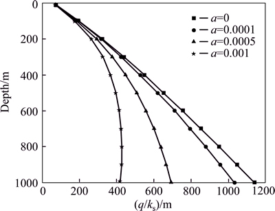
Fig. 6 Variation of q/ks changing with depth and a at r=8 m
3) The depth of maximum water inflow is a function in relation to a. With a rises, the depth of the maximum water inflow decreases.
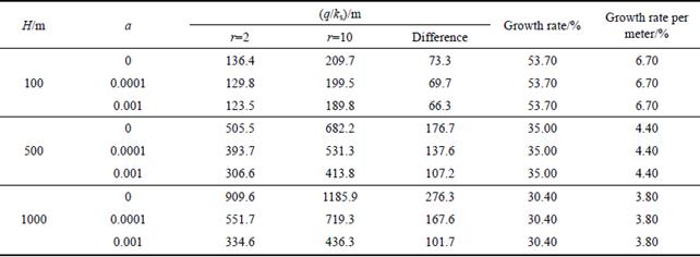
4) Figure 7 indicates that at the same depth, water inflow grows with diameter increasing. However, the variation in the radius of the tunnel has inconspicuous effect on water inflow. Table 4 shows that the radius grows by 1 m, but the water inflow just grows by 6.7%, and the greater the depth, the smaller the growth rate. The conclusion just is in according to some engineering practice that the water inflow in horizontal pilot is almost equal to main tunnel.
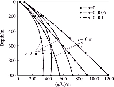
Fig. 7 Comparison diagram of water inflow between r=2 and r=10
Table 4 Change rate of water inflow with radius
6 Conclusions
1) Considering permeability coefficient varying with depth, the formula for predicting tunnel water inflow in non-homogeneous and isotropic surrounding rock is deduced. When ignoring the variation, the formula degenerates to Goodman empirical formula which is used for homogeneous isotropic surrounding rock.
2) Compared to ZHANG and TANI methods, the value of proposed method in this work is a little higher, which provides the safety coefficient and is more secure for engineering. Most of all, the presented method equation is simple and easy to calculate by numerical method, which is convenient to utilize and can provide a reference for related project.
3) After considering the permeability coefficient nonlinear changing with depth, the tunnel water inflow is less than that without considering the change, and the greater the gradient, the larger the range of the decrease amount of water inflow. When ignoring tunnel permeability changes, the water inflow monotonically increases with depth. When taking the variation into consideration, the water inflow increased first till reached the peak value, then decreased and was close to zero finally. Therefore, during site selection, the tunnel should avoid being located at the place where the water inflow is the maximum to reduce the cost for water plugging and dealing with water damage, and ensures the safety of construction and operation.
4) The variation in the radius of the tunnel has inconspicuous effect on water inflow, at which the water inflow just grows by 6.7% when the radius of tunnel increases by 1 m.
In general, different places have different hydrogeological and geological conditions because it is impossible to predict the magnitude water inflow accurately by only one method now. So during water inflow forecast, variety of methods should be adopted to eliminate the error caused by the only method.
References
[1] ZHANG L, FRANKLIN J A. Prediction of water flow into rock tunnels: An analytical solution assuming a hydraulic conductivity gradient [J]. International Journal of Rock Mechanics and Mining Sciences and Geomechanics Abstracts, 1993, 30(1): 37-46.
[2] FERNANDEZ G, MOON J. Excavation-induced hydraulic conductivity reduction around a tunnel, part 1: guideline for estimate of ground water inflow rate [J]. Tunnelling and Underground Space Technology, 2010, 25(5): 560-566.
[3] FERNANDEZ G, MOON J. Excavation-induced hydraulic conductivity reduction around a tunnel, part 2: Verification of proposed method using numerical modeling [J]. Tunnelling and Underground Space Technology, 2010, 25(5): 567-574.
[4] TANI M E. Circular tunnel in a semi-infinite aquifer [J]. Tunnelling and Underground Space Technology, 2003, 18(1): 49-55.
[5] FERNANDEZ G. Behavior of pressure tunnels and guidelines for liner design [J]. Journal of Geotechnical Engineering, 1994, 120(10): 1768-1791.
[6] LEI S. An analytical solution for steady flow into a tunnel [J]. Ground Water, 1999, 37(1): 23-26.
[7] SHIN J H, SHIN Y S, KIM S H, SHIN H S. Evaluation of residual pore water pressure on linings for undersea tunnels [J]. Chinese Journal of Rock Mechanics and Engineering, 2007, 26(S2): 3682- 3688.
[8] SHIN J H. Analytical and combined numerical methods evaluating pore water pressure on tunnels [J]. G��otechnique, 2009, 60(2): 141-145.
[9] TANI M E. Water inflow into tunnels [C]// Proceedings of the World Tunnel Congress ITA-AITES 1999. Oslo: Balkema, 1999: 61-70.
[10] LI Di-yuan, LI Xi-bing, LI Charlie C, HUANG Bing-ren, GONG Feng-qiang, ZHANG Wei. Case studies of groundwater flow into tunnels and an innovative water-gathering system for water drainage [J]. Tunnelling and Underground Space Technology, 2009, 24(3): 260-268.
[11] WANG Tan-hua. Study of fissured rock mass hydraulics based on 3-D network simulation and nonlinear prediction of gushing water in tunnel [D]. Changchun: Jilin University, 2008. (in Chinese)
[12] XU Ze-min, YANG Li-zhong, HUANG Run-qiu. Method of images for rate of the extra-long tunnels with superthick overburden [J]. Journal of Railway Engineering Society, 2000, 17(1): 55-58. (in Chinese)
[13] HWANG J H, LU C C. A Semi-analytical method for analyzing the tunnel water inflow [J]. Tunnelling and Underground Space Technology, 2007, 22(1): 39-46.
[14] CHENG Pan, LI Liang, ZOU Jin-feng, ZHAO Lian-heng, LUO Wei. Determination method for water discharge of tunnel based on the ecological water requirement of vegetation [J]. Journal of China Railway Society, 2013, 35(7): 107-113. (in Chinese)
[15] GIACOMINI A, BUZZI O, FERRERO A M, MIGLIAZZA M, GIANI G P. Numerical study of flow anisotropy within a single natural rock joint [J]. International Journal of Rock Mechanics and Mining Sciences, 2008, 45(1): 47-58.
[16] WAN Li, JIANG Xiao-wei, WANG Xu-sheng. A common regularity of aquifers: the decay in hydraulic conductivity with depth [J]. Geological Journal of China Universities, 2010, 16(1): 7-12. (in Chinese)
[17] HSU S M, LO H C, CHI S Y, KU C Y. Rock mass hydraulic conductivity estimated by two empirical models [M]// Developments in Hydraulic Conductivity Research. InTech, 2011: 134-158.
[18] JIANG X W, WAN L, WANG X S, GE S M, LIU J. Effect of exponential decay in hydraulic conductivity with depth on regional groundwater flow [J]. Geophysical Research Letters, 2009, 36(24): L24402.
[19] JIANG X W, WAN L, CARDENAS M B, GE S M, WANG X S. Simultaneous rejuvenation and aging of groundwater in basins due to depth-decaying hydraulic conductivity and porosity [J]. Geophysical Research Letters, 2010, 37(5): L05403.
[20] JIANG X W, WAN L, WANG X S, LIANG S H, HU B X. Estimation of fracture normal stiffness using a transmissivity-depth correlation [J]. International Journal of Rock Mechanics and Mining Sciences, 2009, 46(1): 51-58.
[21] WANG X S, JIANG X W, WAN L, SONG G, XIA Q. Evaluation of depth-dependent porosity and bulk modulus of a shear using permeability�Cdepth trends [J]. International Journal of Rock Mechanics and Mining Sciences, 2009, 46(7): 1175-1181.
[22] JIANG X W, WANG X S, WAN L. Semi-empirical equations for the systematic decrease in permeability with depth in porous and fractured media [J]. Hydrogeology Journal, 2010, 18(4): 839-850.
[23] CHENG Pan. Groundwater seepage and control method for tunnel and limiting drainage criterion based on ecological balance [D]. Changsha: Central South University, 2014. (in Chinese)
[24] LOUIS C. Rock hydraulics in rock mechanics [M]. New York: Springer Verlag, 1974.
[25] POLUBARINOVA-KOCHINA I, de WIEST R J M. Theory of ground water movement [M]. Princeton J: Princeton University Press, 1962.
(Edited by YANG Hua)
Cite this article as:
CHENG Pan, ZHAO Lian-heng, ZHANG Shao-wei, LI Liang, SHEN Zhi-qiang, NING Peng-fei, ZHANG Ze-hai. Water inflow forecasting for tunnel considering nonlinear variation of permeability coefficient [J]. Journal of Central South University, 2017, 24(7): 1612-1618.
DOI:https://dx.doi.org/10.1007/s11771-017-3566-xFoundation item: Projects(51478477, 51508562, 51508563) supported by the National Natural Science Foundation of China
Received date: 2015-12-16; Accepted date: 2016-08-01
Corresponding author: ZHAO Lian-heng, Professor, PhD; Tel: +86-731-13755139425; E-mail: zlh8076@163.com
Abstract: To assess the water inflow which is more suitable to the actual conditions of tunnel, an empirical correlation about the permeability coefficient changing with depth is introduced. Supposing that the surrounding rock is heterogeneous isotropy, the formula for calculating water inflow of tunnel with the nonlinear variation of permeability coefficient is deduced. By the contrast analysis with the existing formulas, the presented method has the similar value to them; moreover, the presented method has more simple form and easy to use. Due to parameter analysis, the water inflow decreases after considering the nonlinear variation of permeability coefficient. When the attenuation coefficient a>0, the water inflow increases first till reaches the maximum at a certain depth, then decreases and is close to 0 finally if deep enough. Thus, it is better to keep away from the certain depth where it is with the maximum water inflow for safe operation and economical construction, and reduce the water damage. Based on the analysis, the radius of tunnel has less impact on the amount of water inflow, and the water inflow just increases by 6.7% when the radius of tunnel increases by 1 m.
