
J. Cent. South Univ. Technol. (2010) 17: 180-186
DOI: 10.1007/s11771-010-0028-0 ![]()
Numerical analysis on thermal regime in double-loop channel inductor
ZHAO Tao(����)1, OU Shao-duan(ŷ�ٶ�)1, ZHOU Jie-min(������)1, XIONG Jia-zheng(�ܼ���)2
1. School of Energy Science and Power Engineering, Central South University, Changsha 410083, China;
2. Zhuzhou Torch Industrial Furnace Limited Company, Zhuzhou 412005, China
? Central South University Press and Springer-Verlag Berlin Heidelberg 2010
Abstract:
In order to investigate the temperature distribution, a three-dimensional finite element model (FEM) was developed to simulate the temperature regime in the channels of double-loop inductor, and the simulated results were compared with experimental data from low load trials of a 400 kW inductor. The results of numerical simulations, such as the temperature and Joule heating rate, show reasonable correlation with experimental data. The results indicate that Joule heating rate and the temperature reach the maximum at the corners and the minimum at the centre of the cross-section area. The temperature difference between the inlet and outlet is in an inverse proportion to mass transport. Joule heating rate and the temperature are directly proportional to power frequency. It is concluded that mass transport and power frequency play a critical role in determining the temperature regime and Joule heating rate, the relative permeability of the magnetic core shows no significant influence on temperature regime and Joule heating rate, when the relative permeability varies from 5 000 to 10 000.
Key words:
numerical simulation; inductor; finite element method; Joule heating rate��
1 Introduction
Twin-channel induction furnaces are extensively used for melting and holding metals and alloys in many processing industries. This is due to their high overall efficiency, good degassing and homogenization of the melt, low oxide and slag formation and low energy cost [1-2]. It is generally accepted that the function of the inductor is to induce high electric current densities in the channels and heat the metal through Joule heating [3-4]. The principle of a double-channel induction furnace is based on the effect of electromagnetic induction and significant axial flows along the channels axes are detected [5-7].
The thermal regime in the channel has been investigated mainly by simplified analytical models and by full-scale finite element analysis (FEA). Unfortunately, the application of simplified analytical models is limited because they are complex, lack of flexibility and the cost is high. For further studies, the most commonly used tool is the finite element method. RAPPAZ and SWIERKOSZ [8] conducted mathematical modeling and simulation of induction heating processes. BODART et al [9] performed numerical investigation of optimal control of induction heating process.
It is evident that the coupled physical phenomena involved in the function of the channel induction furnaces are not fully understood and experimental investigations using cold mercury or Wood��s metal are inadequate and unrealistic. The present work is an attempt to predict the thermal regime and Joule heating rate of double-loop channel in a 400 kW inductor using the finite element analysis software.
2 Thermal model
2.1 Analysis software
The channel induction furnace is a good example of coupled field engineering system, which explains its complexity and difficulty in predicting the behaviors of the molten metal under normal and abnormal operating conditions. In induction furnaces, electrical, electro- magnetic, gravitational phenomena, fluid flow and heat transfer continuously interact in a non-linear fashion. Computer modeling of such a system will ideally require direct coupling of all these phenomena, preferably in a single software package. However, this is still impractical for the following reasons. There is no software packager that is capable of coupling all the above-mentioned physical phenomena simultaneously, one of the better known packagers can couple two or three fields such as electromagnetic-thermal to predict temperature; coupling of all involved phenomena is inefficient, computing time is very long and software cost is high [8-9]; modelers of high level of skill in different fields are required.
For engineering purpose it might be adequate to model using an electromagnetic-thermal packager with carefully selected boundary conditions. In the current work the finite element analysis software is used, which can couple electromagnetic-thermal fields to predict Joule heating rate and investigate in the temperature field in the double-channel of an inductor. The software is ANSYS 8.0, which possesses graphical modeler and can be used as 3D interactive pre- and post-processor. Fig.1 shows the process of electromagnetic-thermal fields to predict Joule heating rate and temperature regime in the channel. Fig.2 shows the 3D model of the 400 kW inductor generated by the graphical modeler. The model is used to predict the thermal regime of double-loop channel.
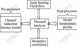
Fig.1 Electromagnetic-thermal field analysis scheme
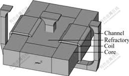
Fig.2 Diagram of 400 kW inductor model
2.2 Input data
The input data required for the electromagnetic- thermal analysis included material properties, such as thermal conductivity, specific heat, density and resistivity, the thermal boundary conditions, input heat rate and mass transport of the molten metal in the channels being required only if the load was given as current density. Material properties were obtained from published data and were assumed to be constant, temperature dependent or temperature difference. In this work, the properties were assumed to be constant. The heat losses to the surroundings include both convection and radiation heat transfer from the outside surface to the surroundings at ambient temperature and from the inner surface of the duck of the coil-iron core assembly to the air provided to cool the coils. The estimation of the input heat and mass transport is more problematic and the approaches used in this work are outlined below.
2.2.1 Mass transport
Only the axial flow speed out of the side channels contributing to mass transport between the inductor and the pot was considered and the vortex flow in the cross-sectional areas of the channels was neglected. Electromagnetic compression forces act mainly in the plane perpendicular to the axes of the channels and seem to have a bearing on the unidirectional flow [10-11] of the melt in the direction of the axes of the channels, which contributes to the pinching and cavitations in the channels. Estimation of the unidirectional flow rate of the melt has been made by mathematical modeling, physical modeling and computer modeling [12]. However, these models were developed mainly for small scale systems with low energy input. The approach used in this work was based on simple first-law analysis of steady state steady flow (SSSF) process in the system and a formula was proposed to estimate unidirectional flow rate of the melt in the direction of the axes of the channels [13].
![]() (1)
(1)
where Ce is the unidirectional flow rate of the melt in the direction of the axes of the side channels, m/s; P is the net energy rate input into the system, kW; ��t is the temperature increase between the inlet to the central channel and exit from the side channels, ��; k is a constant for given system and is dependent on the geometry of the inductor and properties of the melt. Eq.(1) indicates that the mass transport is directly proportional to the input heat and inversely to the temperature difference, and this correlation is generally supported by experiments. Fig.3 shows that for a given ��t, Ce changes linearly with P and a temperature gradient change from 50 to 10 �� at a constant P is accompanied with a fivefold increase in the flow velocity in the side channel. Research in the laboratories of the German industrial group ABB indicates a fourfold velocity increase for the same temperature range in a 1 500 kW double-channel induction furnace for aluminum [14]. Fig.3 shows the previously published data and the represented data published by VIVES and RICOU [6]. These data related to actual measurements of flow rate in a four-tenth stainless steel model of 1 300 kW inductor unit using cold mercury.
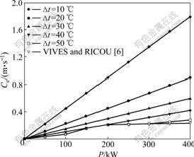
Fig.3 Mass transport as function of input heat P and temperature difference ��t
Table 1 shows the measurements of the unidirectional flow rate in the direction of the axes of the channels in a low load trial for a 400 kW inductor. The inductor for experiment is shown in Fig.4, where A and B are the coils, and C is the iron core. The average transit flow of the melt metal through the channel was measured under different conditions of current density. The metal zinc was heated to 480 �� in a crucible furnace and poured in the inductor. The level of liquid metal was higher than the channel��s inlet and outlet of 50-100 mm. After the inductor being stable with adjusting the input voltage, the temperature difference of liquid metal between inlet and outlet and the output power of the inductor were measured. Under different conditions of the output power, the average transit flow of the melt metal through the channel is expressed by Eq.(1). In Table 1, t1 is the temperature of the molten melt Zn at the inlet of central channel, t2 is the temperature of the molten melt Zn at the outlet of side channels, ��t is the temperature difference between t2 and t1, and I is the alternating current in the coils. It shows reasonable correlation between reported data from Fig.3 and the measurements from low power trial.
Table 1 Average transit flow at different output powers
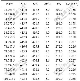
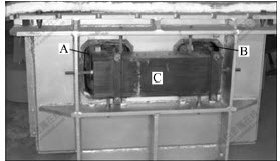
Fig.4 Photo of inductor for experiments
2.2.2 Input heat
The input heat was Joule heating by current induced in the channels. Joule heating can be concluded in an electromagnetic analysis, which was used in a thermal analysis to predict a temperature solution. The coupling between the electromagnetic field and the thermal field was accomplished by load sequential coupling and the Joule heating transfer taking place across volumes. This approach linked different physics environments in a coupled-field analysis and enabled you to read in the Joule heating results from the electromagnetic environment analysis and apply them as loads for the thermal environment��s solution.
In this work, the molten metal was pure zinc and the refractory as alumina. The thermal boundary conditions were taken as constant heat flow rate. The heat efficiency was assumed between 70% and 95%, corresponding to different loads.
3 Results and discussion
3.1 Geometrical convergence
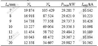
First, the geometrical convergence of the 3D model was tested. For this purpose, the model was recalculated for several different discretizations that differed mainly in meshing of the channel area. Variations of the total heating power and total current through the channel were observed. The dependence of the heating power and current through the channel on the maximum edge size of elements in the subdomains representing the channel is displayed in Table 2.
In Table 2, Le is the maximum element edge size in the area of the channel, Nn is the number of nodes, Ne is the number of elements, PJoule is the heating power, and Ieddy is the inducted current passing through the channels. It can be concluded that the fluctuations of the heating power and current in the inductor are small and can be neglected.
Table 2 Dependence of meshing of channel on heating power and current through inductor
3.2 Temperature distribution
The model was then applied to testing the temperature distribution in the channel. The problem was solved on a mesh consisting of ![]() nodes and 190 538 elements, and the maximum edge in the channel area was set to be 7 mm. The input current of coils was 190 A, and the power frequency was 50 Hz. The temperature of pure zinc at inlet of the channel was 415 ��.
nodes and 190 538 elements, and the maximum edge in the channel area was set to be 7 mm. The input current of coils was 190 A, and the power frequency was 50 Hz. The temperature of pure zinc at inlet of the channel was 415 ��.
The simulated results and the measurements in low load trial for 400 kW inductor are shown in Table 3. In Table 3, I1 is the current of the coils, I2 is the simulated results of eddy, P�� is the simulated result of Joule heating, ![]() is the simulated result of the average temperature of molten zinc at exit of side channel, and
is the simulated result of the average temperature of molten zinc at exit of side channel, and ![]() is the temperature difference between t1 and
is the temperature difference between t1 and ![]() . Table 3 shows that when the boundary conditions and parameters are set correctly, the simulated results agree reasonably with the measurements.
. Table 3 shows that when the boundary conditions and parameters are set correctly, the simulated results agree reasonably with the measurements.
Table 3 Simulated results and measurements in low load trial for 400 kW inductor

Fig.5 shows the temperature contours in the channel. The Joule heating rate is 32.163 7 kW and the current passing through the channel is 11.032 kA. These results show that the molten metal pure zinc is heated continuously as it moves from the central channel to the side channels, reaching the maximum temperature on the interface between the melt and the refractory in the side channels and at the exits of the side channels.
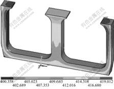
Fig.5 Temperature contour of pure zinc in channel (Unit: ��)
Fig.6 shows Joule heating rate and the temperature contours of pure zinc on the cross-section area of the channel. The cross-section area is located below the inlet of channel 0.30 m. Joule heating rate and the temperature reach the maximum at the corners and the minimum at the centre of the cross-section area. The ratio between the minimum and the maximum of Joule heating rate is 0.736 8 and that of the temperature is 0.996 1. Joule heating rate is not uniform on the cross-section, which is controlled by the distribution of eddy passing through the channel. The temperature distribution is uniform in the cross-section area of the channel due to the flow of molten zinc. This is one of the advantages of the 50 Hz double-loop channel induction furnace, which enhances the life of the inductor.
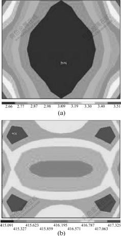
Fig.6 Joule heating rate and temperature contours of pure zinc on cross-section area of channel below inlet 0.30 m: (a) Joule heating rate on cross-section area of channel (Unit: MW/m3); (b) Temperature contour of pure zinc on cross-section area of channel (Unit: ��)
3.3 Relative permeability
The model with rectangular cross-section of the channel was computed for relative permeability ��r of the magnetic core increasing from 5 000 to 10 000. Table 4 shows the simulated results under condition that the eddy loss of iron core was not considered.
In Table 4, PJoule is the Joule heating rate, Ieddy is the current inducted passing through the channel, tcen is the temperature at the centre of the cross-section area, tcon is the temperature at the corner of the cross-section area, and text is the temperature at the central node of the side channels. Slight increases of the temperature at the exit of sides channel and Joule heating rate have been observed. The increases of Joule heating rate and the temperature at the exit of the channel are small in contrast with the improvement of relative permeability. For example, Joule heating rates are 32.163 7 and 32.321 8 kW and the temperatures at the exit of the channel are 421.343 �� and 421.401 �� for the two cases with low (5 000) and high (10 000) relative permeability, respectively.
Table 4 Simulated results while relative permeability changing from 1 000 to 10 000
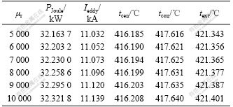
This indicates that the relative permeability is not the main factor influencing the thermal regime of channel in this work. The electromagnetic field is canalized by the high permeable laminated core, the leakage flux and, in turn, the corresponding losses of electrical energy caused by the Joule effect in the surrounding conductors are attenuated. Because the eddy loss of iron core cannot be estimated by the codes used in this work, further research is required to analyze the influence of relative permeability of the magnetic core on inductors.
3.4 Mass transport
The same value of relative permeability (��r=5 000) was used to investigate the influence of mass transport on the temperature in the channel. Fig.7 shows the effect of mass transport on temperature difference between the inlet and outlet of the channel.
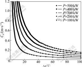
Fig.7 Effect of mass transport on temperature difference between inlet and outlet of channel
From Fig.7, it can be seen that ��t decreases with the increase of Ce when P is constant. For example, when P is 500 kW, ��t is approximately 80, 40 and 25 �� in three mass transport cases: low (0.20 m/s), intermediate (0.40 m/s) and high (0.60 m/s) flow speeds. ��t increases with decreasing Ce as a result of increased residence time. For certain input power of coils P, there is a range of Ce, in which ��t is influenced obviously. For example, when P is 100 kW and Ce varies from 0.06 to 0.60 m/s, ��t decreases respectively from 60 to 6 ��. Fig.7 shows that for a given P, Ce changes hyperbolically with ��t.
These indicate that mass transport plays a critical role in determining the temperature regime of the inductor. High mass transport rate can take the heat from the channel to the pot and reduce the degree of overheating in the channel. Further research will be required to quantify the optimum flow rate for a particular design if durability issues of inductors are to be addressed.
3.5 Power frequency
The model was computed for power frequency f varying from 50 to 500 Hz to investigate the influence of power frequency on the temperature of molten zinc in the channel. The temperature at the inlet was taken as 415 �� and input current of coils as 190 A. Table 5 shows the simulated results.
Table 5 Results of f between 50 and 500 Hz
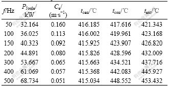
From Table 5, it can be seen that Joule heating rate improves obviously with the increase of power frequency. When frequency increases from 50 to 500 Hz, Joule heating rate rises from 32.164 to 68.734 kW and the increase rate is 114.0%. text rises quickly with the increase of f as a result of increasing PJoule and decreasing of Ce. On the cross-section, tcen changes a little and tcon changes notably with the increase of f as a result of eddy effect of current inducted passing through the channel. For example, when f increases from 50 to 500 Hz, tcen varies from 416.185 to 415.034 �� and tcon from 417.616 to 448.552 ��, respectively.
These indicate that power frequency plays a critical role in determining the temperature regime and Joule heating rate in the channel as a result of phenomenon of electromagnetic induction. Because the increase in power frequency enhances the energy and energy convey of electromagnetic field, more energy reserves are required to convey electromagnetic waves in space. As a result, the impendence and reactive power in the system increase. With the increase of power frequency, the temperature of molten metal at the exit of side channel and at the corner of the cross-section area increases, the axial flow rate decreases obviously, and the temperature at the centre of the cross-section area does not change significantly as a result of the skin effect of eddy in the channel. Further research is required to quantify the optimum power frequency for a particular design if durability and efficiency issues of inductors are to be addressed.
4 Conclusions
(1) Because good electromagnetic coupling of the magnetic core in double-channel induction furnace, increasing relative permeability of the magnetic core is not an efficient approach to enhance Joule heating rate and thermal regime in the channel, when relative permeability of the magnetic core is greater than a certain value, for example, 5 000 in this work.
(2) Mass transport plays a critical role in determining the temperature regime of the channel. For certain input power of coils, high mass transport can reduce the degree of overheating in the channel and, in turn, increases the life of refractory component of the inductor. Optimum flow rate value for a particular design is an important factor influencing the performance of the double-loop channel inductor.
(3) High power frequency is beneficial to Joule heating rate. However, it also aggravates the degree of overheating in the channel. Joule heating rate and the temperature of molten metal at exit of side channel increase obviously with the increase of power frequency. The suitable power frequency is an important element influencing the performance of the double-loop channel inductor.
(4) During the development of the model, only when the boundary conditions and parameters are set correctly, the simulated results show reasonable agreement with the measurements. FEA is an effective approach to study on the induction heating.
(5) Only the flow out of the side channels contributing to mass transport between the inductor and the pot was considered and the vortex flow in the cross-sectional areas of the channels was neglected. In fact, because the vortex flow pattern in the cross-sectional areas of the channels improved the convection heat transfer in the channel, the overheating degree in the channel maybe is lower than the simulated result.
Further work, both experimental and analytical, is required to quantify the flow rate in double-channel inductors and correlate that with input energy and temperature regime in the inductor. The current model can be used by inductor designers to predict the temperature regime of the inductor under different loading regimes and to prevent premature inductor failure.
References
[1] ZHANG Shu-fang. Induction heating manual [M]. Beijing: Defense Industry Press, 1985. (in Chinese)
[2] JIN Xiao-chang. Surface effects in induction heating [J]. Wuhan Institute of Chemical Technology Journal, 1995, 17(4): 65-68. (in Chinese)
[3] ZINN S, SEMIATIN S L. Elements of induction heating: Design, control, and applications [M]. Detroit: American Association of Metal, 1988.
[4] HAN Zhi-cheng. Electromagnetic metallurgy [M]. Beijing: Metallurgical Industry Press, 2001. (in Chinese)
[5] MOROS A, HUNT J C R. Recalculating flows in the cross-section of a channel induction furnace [J]. Heat Mass Transfer, 1988, 31(7): 1497-1515.
[6] VIVES C, RICOU R. Magnetohydrodynamic flows in a channel induction furnace [J]. Metal Trans, 1991, 22B: 193-209.
[7] DREWAK R, MUHLBAUER A. Controlling heat transfer in a channel-induction furnace [C]// Proceedings of Advances in Engineering Heat Transfer. London, 1997.
[8] RAPPAZ J, SWIERKOSZ M. Mathematical modeling and simulation of induction heating processes [J]. Appl Math Comp Sci, 1996, 6(2): 207-222.
[9] BODART O, BOUREAU A V, TOUZANI R. Numerical investigation of optimal control of induction heating process [J]. Appl Math Modeling, 2001, 25: 697-712.
[10] DREWAK R, JAKOVICH A, MUHLBAUER A A, NACKE B. Experimental and numerical investigations of the melt flow in channel-induction furnaces [J]. Magnitnaya Gidrodinamica, 1996, 32(4): 433-443.
[11] ZHAO C, FAUTRELLE Y, SZEKELY J. Turbulent fluid flow in induction furnaces [C]// Proceedings of the 121st TMS Annual Meeting. San Diego, 1991.
[12] SUN Jun-sheng, WU Chuan-song. The electromagnetic force and its influence on the weldpool fluid flow in MIG welding [J]. Acta Phys Sin, 2001, 50: 209-216. (in Chinese)
[13] ZI Bing-tao, YAO Ke-fu. Numerical simulation of liquid alloy flow field during solidification under applied pulsed magnetic field [J]. Acta Phys Sin, 2003, 52: 115-119. (in Chinese)
[14] HEGEWALDT F, WICKER H. Mathematical modelling in electromagnetism [C]// Proceedings of the International Seminar on Optimising Channel Inductors. Leningrad, 1989.
Foundation item: Project(50876116) supported by the National Natural Science Foundation of China; Project(2007CK3077) supported by the Innovative Program of Hunan Science and Technology Agency, China; Project(1343-77225) supported by the Graduate School of Central South University, China
Received date: 2009-03-07; Accepted date: 2009-05-19
Corresponding author: ZHAO Tao, Doctoral candidate; Tel: +86-13054178261; E-mail: csuzhaotao@yahoo.com.cn
(Edited by YANG You-ping)
Abstract: In order to investigate the temperature distribution, a three-dimensional finite element model (FEM) was developed to simulate the temperature regime in the channels of double-loop inductor, and the simulated results were compared with experimental data from low load trials of a 400 kW inductor. The results of numerical simulations, such as the temperature and Joule heating rate, show reasonable correlation with experimental data. The results indicate that Joule heating rate and the temperature reach the maximum at the corners and the minimum at the centre of the cross-section area. The temperature difference between the inlet and outlet is in an inverse proportion to mass transport. Joule heating rate and the temperature are directly proportional to power frequency. It is concluded that mass transport and power frequency play a critical role in determining the temperature regime and Joule heating rate, the relative permeability of the magnetic core shows no significant influence on temperature regime and Joule heating rate, when the relative permeability varies from 5 000 to 10 000.
