

J. Cent. South Univ. (2018) 25: 121-130
DOI: https://doi.org/10.1007/s11771-018-3722-y

Design of novel sliding-mode controller for high-velocity AUV with consideration of residual dead load
JIANG Chun-meng(������), WAN Lei(����), SUN Yu-shan(����ɽ), LI Yue-ming(������)
Science and Technology on Underwater Vehicle Laboratory, Harbin Engineering University,Harbin 150001, China
 Central South University Press and Springer-Verlag GmbH Germany, part of Springer Nature 2018
Abstract:
This work focuses on motion control of high-velocity autonomous underwater vehicle (AUV). Conventional methods are effective solutions to motion control of low-and-medium-velocity AUV. Usually not taken into consideration in the control model, the residual dead load and damping force which vary with the AUV��s velocity tend to result in difficulties in motion control or even failure in convergence in the case of high-velocity movement. With full consideration given to the influence of residual dead load and changing damping force upon AUV motion control, a novel sliding-mode controller (SMC) is proposed in this work. The stability analysis of the proposed controller is carried out on the basis of Lyapunov function. The sea trials results proved the superiority of the sliding-mode controller over sigmoid-function-based controller (SFC). The novel controller demonstrated its effectiveness by achieving admirable control results in the case of high-velocity movement.
Key words:
Cite this article as:
JIANG Chun-meng, WAN Lei, SUN Yu-shan, LI Yue-ming. Design of novel sliding-mode controller for high-velocity AUV with consideration of residual dead load [J]. Journal of Central South University, 2018, 25(1): 121�C130.
DOI:https://dx.doi.org/https://doi.org/10.1007/s11771-018-3722-y1 Introduction
With the advancement of automatic control [1], computer simulation and artificial intelligence [2], significant progresses have been made in AUV technologies. The widespread application has made AUV an important tool for underwater operations.
The AUV system is featured with strong nonlinearity and significant coupling effect among degrees of freedom [3, 4]. How well the AUV completes an operation, to a large extent, depends on the control quality [5]. A number of AUV control algorithms have been put forward for the purpose of successful completion of different operations. LI et al [6] designed fuzzy PD controller that took both overall and local control effects into consideration, and the simulation results showed its superiority over those with fixed parameters. By combining fuzzy logic with sliding-mode control, HOSSEIN et al [7] solved the buffeting problem in AUV sliding-mode control. ISHAQUE et al [8] applied fuzzy technologies to AUV motion control and proved the superiority of fuzzy controller over PID controller. BAGHERI et al [9] put forward neural network-based adaptive output feedback method which effectively overcomes the influence of nonlinear hydrodynamic characteristics on the entire system. HU et al [10] developed dynamic feedback algorithm based on neural network compensator. KIM et al [11] proposed distributed sliding-mode control system whose robustness to external disturbance was verified. JAVADI- MOGHADDAM et al [12] provided sliding-mode control method based on genetic algorithm. The genetic algorithm was adopted for the optimization of controller parameters in order to solve the buffeting problem. Based on fuzzy logic and adaptive control, FANG et al [13] effectively solved AUV motion control. All the methods mentioned above were proved to be effective in AUV motion control in simulation tests and sea trials, but they require multiple control parameters and complicated parameter adjustment process. In accordance with amount of trials and engineering practice, LIU et al [14] referred to PD control structure and theory of fuzzy control and put forward a sigmoid-function-based controller which involves few control parameters. By introducing the adaptive module, SUN et al [15] improved the sigmoid-function-based controller whose superiority was proven in lake and sea trials.
The mentioned methods and sigmoid-function- based controller satisfactorily served low-and- medium-velocity AUV motion control and their feasibility and effectiveness have been verified in simulation tests and sea trials. Without consideration of residual dead load in model construction and damping force that changes with the AUV��s velocity, high-velocity motion control is challenged with difficulties or even failure with convergence. In order to solve this problem, a novel sliding-mode controller is put forward in this work. Taking into consideration of residual dead load and changing damping force, the property of sigmoid- function-based controller, namely the simple structure and few parameters, is reserved in the proposed controller which effectively served for high-velocity AUV motion control and its feasibility and effectiveness were verified in field trials.
The structure design as well as hardware and software system of the research object is introduced in the second section. The frames and six-degree- of-freedom equations of the research object are established in the third section. A novel sliding- mode controller is put forward in the fourth section together with the stability analysis. Sea trial results are provided in the fifth section which verified the effectiveness of the proposed controller.
2 Architecture of high-velocity AUV
2.1 Design of high-velocity AUV
The research object is a multi-functional AUV that can realize motion control, long-distance navigation, submarine topographic mapping, pipeline and dam detection as well as target recognition [16]. In order to realize the functions above, the AUV is designed with streamlined appearance and equipped with stabilizer fins to improve stability.
As shown in Figure 1, approximately 5 m long, the AUV weighs 1.6 t with a maximum diameter of 0.78 m. Its system satisfies operations of autonomous planning, navigation, basic control, target detection and emergency rescue, etc. The autonomous planning system provides target instructions and the navigation system provides position information. The basic control system realizes closed-loop control in accordance with the target instructions. The target detection system provides information of the target or obstacle. The rescue system starts in case of emergency. The AUV is designed with slightly larger buoyancy than gravity to make sure that it can come up to in case of failure of power or computer. For the purpose of improved stability, the stabilizer fins are designed in cross shape at the stern.
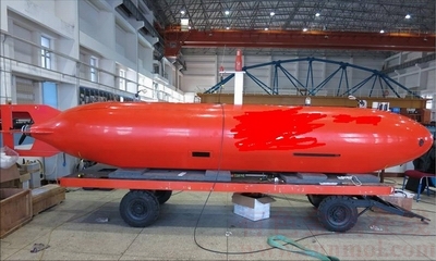
Figure 1 Profile of AUV
The AUV is made up of a pressure hull and a light shell. Made of aluminum alloy, the pressure hull contains the head, tail and main housing [17]. The head and tail are spherical end enclosures and the three parts are connected with waterproof hermetic O-rings. The light shell is designed in streamline shape to reduce resistance in AUV movement. The head and tail of the shell is made of glass steel and the main housing is made of aluminum alloy.
As shown in Figure 2, a unique conduit thruster with cross-shaped rudder, hydroplane and fins is designed at the end to reduce the thrust deduction effect of the thruster and improve the stability of the AUV. The rudder is responsible for heading control and the hydroplane for pitch angle and depth control so that the AUV can realize movement in the horizontal and vertical planes.
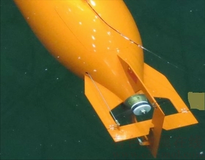
Figure 2 Thruster, rudder and hydroplane at stern
2.2 Hardware architecture of high-velocity AUV
The hardware architecture of the entire control system is shown in Figure 3, including motion control system, navigation system and planning system. All the systems adopt PC/104 and real-time embedded operating system VxWorks [18]. The control system realizes data acquisition and processing, control algorithm, thrust allocation and instruction transmission. The navigation system is connected with INS and GPS. The AUV receives position data from the navigation system via TCP, target instructions from the planning system via UDP, attitude angle from the gyrocompass, velocity from the DVL, depth from the depthometer and altitude from the altimeter via the serial port board, leakage sign from the DIO board, and sends digital rudder angle instructions to the steering engine via the A/D board, analog voltage instruction to the conduit thruster via the D/A board, and switching instruction to SSR via the DIO board.
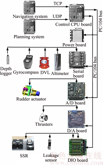
Figure 3 Hardware architecture of motion control system
2.3 Software architecture of high-velocity AUV
VC++ is used for programming for more efficient and transplantable development of the control system [19] and module design is adopted for timely modification and on-line debugging [20]. The software architecture contains modules of sensor data acquisition, data preprocessing and fusion, control algorithm, thrust allocation, thrust instruction sending as well as communication.
As shown in Figure 4, the information flow of the motion control system is composed of four parts. Part I is the module for data processing, which covers data preprocessing and data fusion. Invalid data are eliminated and the target data are linearly smoothened in data preprocessing. Data fusion is conducted after data preprocessing so as to provide the control algorithm with more fault-tolerant and accurate data. Part II is the module for control algorithm. In accordance with the preset objective and data received from the sensors, the AUV is controlled with the desired thrust and rudder force calculated by the control algorithm. Part III is the module for thrust allocation. It implements the thrust allocation algorithm, sends thrust commands to the thrusters and angle instructions to the rudder and hydroplane. Part IV is the hardware module, including the thrusters, rudder actuators and sensors. The thruster provides thrusting force. The rudder actuators change the attitude of the AUV and the sensors acquire motion data of the AUV. Part IV is the most substantial section of the motion control system.
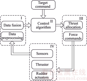
Figure 4 Information flow of motion control system
3 Frames and kinematic equations
3.1 Establishment and transformation of frames
The motion equations of the AUV are established based on the standard symbol system, including the inertial frame and the body frame [21]. The inertial frame describes the attitude angles and the body frame describes the dynamic characteristics of the AUV with the AUV��s center of buoyancy as its origin shown in Figure 5.

Figure 5 Inertial frame and body frame
The transformation between the two frames follows [22]:
 (1)
(1)
 (2)
(2)
where x, y and z are in the body frame while ��, �� and  are in the inertial frame. T stands for the transformation matrix, �� for the heading angle, �� for the pitch angle, f for the rolling angle, c for cos and s for sin.
3.2 Kinematic equations of high-velocity AUV
The kinematic equations of the research object are established as follows [23]:
 (3)
(3)
 (4)
(4)
 (5)
(5)
where X, Y, Z, K, M and N are the forces and moments on the AUV in the body frame. m stands for the mass of the AUV, Ij for the inertia moment projected on each axis of the body frame, and xG, yG and zG for the center of gravity of the AUV. The above equations are simplified as Eqs. (4) and (5), where �� is the vector of linear velocity and angular velocity under the body frame and ���� is the vector of force and moment under the body frame.
The hydrodynamic forces and moments include added mass force, Coriolis force, centripetal force and damping force. When the AUV conducts accelerated moment, added mass force and moment are generated proportionally to the accelerated velocity of the AUV. With a symmetrical profile, most of the added mass and moment coefficients are zero. The matrix of added mass coefficients is described in Eq. (6).
 (6)
(6)
When a rigid body moves in the ideal fluid, the hydrodynamic Coriolis and centripetal force are usually parameterized. The coefficient matrix of hydrodynamic Coriolis is symmetrical as shown in Eq. (7). Highly nonlinear with its moment, the damping force is also the coupling function of linear velocity and angular velocity. Nevertheless, when the AUV is assumed to be symmetrical, items higher than the second order can be ignored. Due to the symmetry, the coefficient matrixes of the linear and nonlinear damping forces are described in Eq. (8).
 (7)
(7)


 (8)
(8)
In addition to the added mass and damping force, the AUV is also subjected to force and moment of gravity and buoyancy. The gravity is defined as W=mg where g is the acceleration of gravity. The buoyancy is defined as B=��gV where �� is the density of water and V is volume of displacement of the AUV. The residual buoyancy and restoring moment are shown in Eq. (9) where  stands for the vector of position and attitude angle under the inertial frame, xB, yB and zB for the center of buoyancy, c for cos and s for sin. The kinematic equations of the AUV can be simplified as Eqs. (10) and (11).
 (9)
(9)
 (10)
(10)
 (11)
(11)
4 Controller design
4.1 Sigmoid-function-based controller
Combining fuzzy control theory with PD control structure, the sigmoid-function-based controller is featured with simple structure and few parameters. It is easy to adjust and use. With improvement and optimization, it has been successfully applied to the motion control of different models of AUV and received admirable control effect. Field trials have proven the feasibility and effectiveness of sigmoid-function- based controller applied to AUV motion control.
The sigmoid-function-based controller operates following the mathematical model [14],
 (12)
(12)
where Oi is the control output (i.e., force or moment) of the ith degree of freedom; ei and  are the control inputs (i.e., deviation and deviation variation rate) of the ith degree of freedom; ki1 and ki2 are the control parameters corresponding to the ith deviation and deviation variation; ��Oi is the external permanent disturbing force adaptively given; fi is the expected force or moment output of the ith degree of freedom; and Ki is the greatest force or moment that can be provided in the ith degree of freedom.
On the basis of the analysis of the mathematical model, the residual buoyancy and restoring moment in Eq. (10) are not taken into consideration as indicated in Eq. (12) which provides only adaptive adjustment. Response lag and even buffeting will be generated in the case of significant residual buoyancy. Also, the damping force that varies with the velocity is very likely to give rise to the difficulty in high-velocity motion control.
4.2 Sliding-mode variable structure controller
Based on the above analysis, a novel sliding-mode controller is put forward with full consideration of the residual dead load and the coupling effect in case of high-velocity movement. The mathematical model of the proposed model is shown in Eq.(13) where F is the output matrix of the controller,  is the estimated residual buoyancy and restoring moment and Ks is the positive diagonal matrix determined by the stability conditions. exp(��u2) takes the varying damping force into consideration, in which �� (��>0) is adjustable and u is the velocity in the surge direction.
 (13)
(13)
where s is defined in Eq. (14).  xd is the target state vector and x is the present state vector.
 (14)
(14)
As indicated in Eq. (15), Lyapunov function is introduced to carry out stability analysis in order to ensure the stability of the proposed control model.
 (15)
(15)
Equation (16) is obtained with the combination of Eqs. (10) and (13), in which  is the difference between the actual residual buoyancy and restoring moment with the estimations.
 (16)
(16)
Equation (17) is justified since D is the positive definite matrix, in which ��{min}D and are the minimum eigenvalues of the corresponding matrix.

 (17)
(17)
If Ks satisfies Eq. (13), then  and Eq.(18) is obtained as follows.
 (18)
(18)
It means that if Ks satisfies Eq. (13), s will converge to zero.
When s=0,  Eq. (19) is obtained with
 <0 (19)
Equation (20) is obtained when Eq. (13) is applied to AUV motion control.
 (i=1, ��, 6) (20)
Velocity control in the surge direction is typically applied in the case of high-velocity movement while position control is applied to the other degrees of freedom. In Eq. (21),  and
and  in which xd is the vector of target state, x is the vector of present state, fi is the force or moment provided in a degree of freedom,
  is the projection of the estimated residual buoyancy or restoring moment on a degree of freedom, ksi is the element at the ith row and ith column in Ks, ��i is the adjustable parameter of degree of freedom i, and
  is the ith element of vector s.
 (21)
(21)
5 Field trials
Sea trials were carried out to verify the analysis in this work. The trial environment is shown in Figure 6. The contrast trials were first carried out to justify the feasibility and superiority of the proposed controller over the original design without consideration of the residual dead load. Then more trials were conducted to verify the effectiveness of the control method. Finally, the stability of the proposed controller and the control system was proven in long-distance navigation trials.
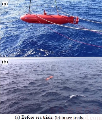
Figure 6 Environment of sea trials:
The contrast trials included velocity control in the surge direction, heading control and depth control. When applied to the foresaid contrast trials, the proposed sliding-mode controller operated with the following parameters: ks1=100, ��11=1.2, ��21=0.6; ks3=100, ��13=3.0, ��23=1.5, ��3=1.0; ks6=500, ��16=0.6, ��26=0.3 and ��6=1.5. It should be noted that sharp depth adjust is not applied in the case of high- velocity (��0.8 m/s) movement, as the result of which, depth control does not take the velocity in the surge direction but the residual buoyancy into consideration.
The contrasts between sigmoid-function-based controller and sliding-mode controller in the case of high-velocity heading control and depth control are shown in Figures 7 and 8, respectively, with the desired heading angle of 90��, desired velocity in the surge direction of 1.0 m/s and desired depth of 3.0 m. The contrasts of heading control results are shown in Figure 7(a) where the black dotted line is the desired heading angle, red solid line the control result with sliding-mode controller and blue solid line the control result with sigmoid- function-based controller. The contrasts of velocity control results are shown in Figure 7(b) where the black dotted line is the desired velocity in the surge direction, red solid line the control result with sliding-mode controller and blue solid line the control result with sigmoid-function-based controller. As suggested in Figure 7, buffeting appeared when the velocity approached 0.8 m/s with the sigmoid-function- based controller. The maximum deviation was approximately 27�� and the controller almost went out of control. The instability in heading control, in turn, gave rise to the difficulty keeping the velocity at the desired state. With the sliding-mode controller, however, the deviation was no more than 3�� and the velocity fluctuated within the allowed range. In Figure 8, the black dotted line is the desired depth, red solid line is the control result with sliding-mode controller and blue solid line is the control result with sigmoid-function-based controller. As shown in Figure 8, the depth was maintained at 2.5 m from 50 s to 100 s because the sigmoid-function-based controller was resisting the residual buoyancy by way of integration during which time the control output was equal with the residual buoyancy. As shown in Figures 7 and 8, with consideration of the residual dead load and the damping force varying with the velocity in case of high-velocity movement, the sliding-mode controller is obviously superior to the sigmoid- function-based controller. The feasibility of the sliding-mode controller was verified.
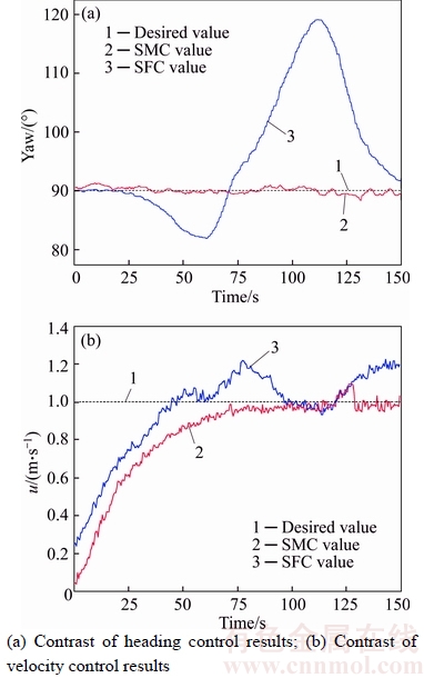
Figure 7 Contrast of heading and velocity control results:
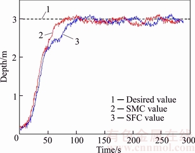
Figure 8 Comparison of depth control results
The control results of velocity in the surge direction and heading angle in the horizontal plane with the sliding-mode controller are shown in Figures 9 and 10 respectively, with the desired velocity ud=1.5 m/s and desired heading angle ��d=30��.In Figure 9, the black dotted line is the desired velocity in the surge direction and the red solid line is the control result of the velocity in the surge direction. There hardly existed overshoot in the velocity output and the error was no more than 0.1 m/s since the steady state. In Figure 10, the black dotted line is the desired heading angle and the red solid line is the control result of the heading angle. The control result is admirable with gentle heading angle output, fast convergence, hardly overshoot, and the error within 2.0�� since the steady state.
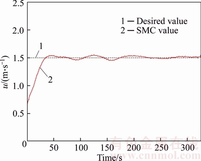
Figure 9 Velocity control in horizontal plane
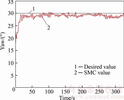
Figure 10 Heading angle control in horizontal plane
The control results of velocity in the surge direction and depth in the vertical plane with the sliding-mode controller are shown in Figures 11 and 12 respectively, with the desired velocity ud=2.0 m/s and desired depth of 20 m. In Figure 11, the black dotted line is the desired velocity in the surge direction and the red solid line is the control result of the velocity in the surge direction. There hardly existed overshoot in the velocity output and the error was no more than 0.15m/s since the steady state. In Figure 12, the black dotted line is the desired depth and the red solid line is the depth control result. The depth output is smooth with fast convergence, hardly overshoot and error within 0.2 m since the steady state. The trial results have proven that the sliding-mode controller can satisfy the requirement on precision in engineering practice.
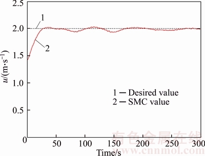
Figure 11 Velocity control result in vertical plane
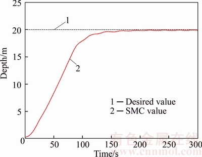
Figure 12 Depth control result in vertical plane
The long-distance navigation result is shown in Figure 13. The priority was given to heading angle and depth control so that the AUV moved in accordance with the preset route. The control results of latitude-longitude, heading angle and depth in the navigation trial are shown in Figures 13(a)�C(c) respectively. The 10-hour route was composed of port-departing, a 15 km��2 km quadrangle and port- entering. For the port-departing and port- entering, the target depth is 0.5 m for clearer observation while for the long-distance navigation the target depth is 2 m. For the safety of the AUV and calibration of underwater navigation data, the AUV came up to the surface on a regular basis. During the sea trials, the harsh environment, changes of seabed terrain and current in the heave direction resulted in failure of some of the sensors, hence the deviation in depth control. The proposed controller, however, can meet the requirement of practical operations in long-distance navigation. The trial results verified the effectiveness and stability of the control system based on the sliding-mode controller.
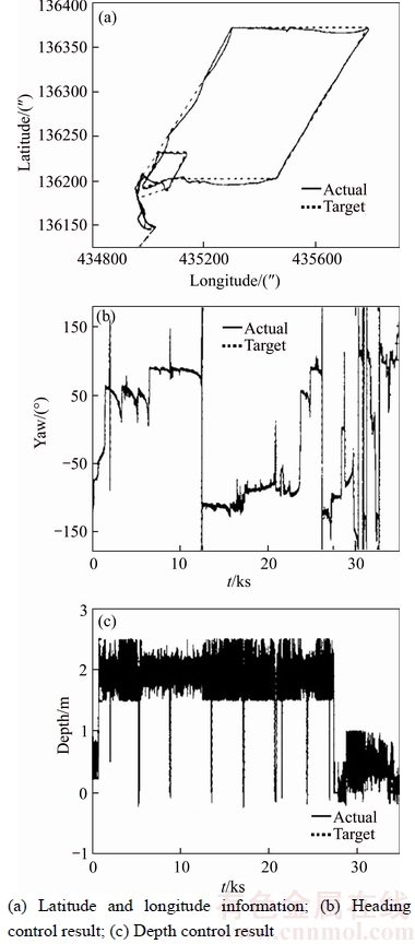
Figure 13 Results of long-distance navigation:
Need to say, in Figure 12, the depth control result is quite smooth and very good. However, in Figure 13, the depth control result is not very smooth. The reason is that the desired depth of the high-velocity AUV is 20 m in Figure 12, and it is stable under the sea; however, in Figure 13, the high-velocity AUV is undertaken long- distance navigation, it should come up to the surface on a regular basis for the safety and calibration of underwater navigation data, therefore, when the high-velocity AUV reached the target depth 2 m, it would keep the condition for a while and then it should go back to the surface usually.
6 Conclusions
1) This work takes into consideration of the residual dead load and the damping force that varies with the velocity in order to solve the difficulty or even failure in convergence in case of high-velocity AUV movement. As indicated by the analysis, the existing control methods can solve the low-and- medium-velocity control problem, but for high- velocity motion control, they fail because the residual dead load and the viscous hydrodynamic force that varies with the velocity are not considered.
2) On the basis of the design, hardware architecture and software architecture of the AUV, two sets of frames are established in accordance with the standard symbol system. The six-degree- of-freedom kinematic equations are also constructed. A novel sliding-mode controller is developed with consideration of the residual dead load and the damping force varying with the velocity, whose stability analysis is then carried out based on Lyapunov function.
3) Field trials were conducted to verify the analysis in this work. The contrast trials proved the superiority of the proposed sliding-mode controller over the sigmoid-function-based controller and justified the feasibility of the sliding-mode controller. The results of high-velocity motion control in the horizontal and vertical planes verified the effectiveness of the proposed sliding-mode controller. The long-distance navigation trial results reflected the stability of the novel controller and the control system. The research object in this work is a 5m-long AUV, but in fact, the research findings are of reference significance to AUVs of different dimensions. The studies and field trials in later stages will emphasize the feasibility and effectiveness of the novel sliding-mode controller applied to AUVs of various dimensions.
References
[1] VU M T, CHIO H S, KANG J, JI D H, JEONG S K. A study on hovering motion of the underwater vehicle with umbilical cable [J]. Ocean Engineering, 2017, 135: 137�C157.
[2] PAN Yun-he. Heading toward artificial intelligence 2.0 [J]. Engineering, 2016, 2: 409�C413.
[3] ALESSANDRO M, GIANLUCA A. Experiments on Sampling/ patrolling with two autonomous underwater vehicles [J]. International Journal of Naval Architecture and Ocean Engineering, 2016, 8(3): 243�C251.
[4] XIANG Xian-bo, LAPIERRE L, JOUVENCEL B. Smooth transition of AUV motion control: From fully-actuated to under-actuated configuration [J]. Robotics and Autonomous Systems, 2015, 67: 14�C22.
[5] JOO M G, QU Z. An autonomous underwater vehicle as an underwater glider and its depth control [J]. International Journal of Control, Automation and Systems, 2015, 13(7): 1212�C1220.
[6] LI Ye, JIANG Yan-qing, WANG Lei-feng, CAO Jian, ZHANG Guo-cheng. Intelligent PID guidance control for AUV path tracking [J]. Journal of Central South University, 2015, 22: 3440�C3449.
[7] HOSSEIN N E, VAHID A, MOHAMMAD D. A time delay controller included terminal sliding mode and fuzzy gain tuning for underwater vehicle-manipulator systems [J]. Ocean Engineering. 2015, 107: 97�C107.
[8] ISHAQUE K, ABDULLAH S S, AYOB S M, SALAM Z. A simplified approach to design fuzzy logic controller for an underwater vehicle [J]. Ocean Engineering, 2011, 38: 271�C284.
[9] BAGHERI A��KARIMI T, AMANIFARD N. Tracking performance control of a cable communicated underwater vehicle [J]. Applied Soft Computing, 2010, 10: 908�C918.
[10] HU Zhong-liang, MA Chao, ZHANG Li-xian, AARNE H, TASAWAR H, BASHIR A. Formation control of impulsive networked autonomous underwater vehicles under fixed and switching topologies [J]. Neurocomputing, 2015, 147: 291�C298.
[11] KIM D, CHOI H S, KIM J Y, PARK J H, TRAN N H. Trajectory generation and sliding-mode controller design of an underwater vehicle-manipulator system with redundancy [J]. International Journal of Precision Engineering and Manufacturing, 2015, 16(7): 1561�C1570.
[12] JAVADI-MOGHADDAM J, BAGHERI A. An adaptive neuro-fuzzy sliding mode based genetic algorithm control system for under water remotely operated vehicle [J]. Expert Systems with Applications, 2010, 137: 647�C660.
[13] FANG Ming-chung, WANG Shun-ming, WU Mu-chen, LIN Yu-Hsien. Applying the self-tuning fuzzy control with the image detection technique on the obstacle-avoidance for autonomous underwater vehicles [J]. Ocean Engineering, 2015, 93: 11�C24.
[14] LIU Xue-min, XU Yu-ru. S control of automatic underwater vehicles [J]. Ocean Engineering, 2001, 19(3): 81�C84.
[15] SUN Yu-shan, WAN Lei, GAN Yong, JIANG Chun-meng. Design of motion control of dam safety inspection underwater vehicle [J]. Journal of Central South University, 2012, 19(6): 1522�C1529.
[16] JIANG Chun-meng, WAN Lei, SUN Yu-shan. Design of motion control system of pipeline detection AUV [J]. Journal of Central South University, 2017, 24(3): 637�C646.
[17] TRAN N H, CHOI H S, BAE J H, OH J Y, CHO J R. Design, control, and implementation of a new auv platform with a mass shifter mechanism [J]. International Journal of Precision Engineering and Manufacturing, 2015, 16(7): 1599�C1608.
[18] REZAZADEGAN F��SHOJAE K I. A novel approach to 6-DOF adaptive trajectory tracking control of an auv in the presence of parameter uncertainties [J]. Ocean Engineering, 2015, 107: 246�C258.
[19] HE Bin, WAN Lei, JIANG Da-peng, ZHANG Guo-cheng. Fuzzy parameter self-optimized s-surface controller based on the prediction model [J]. Journal of Harbin Engineering University, 2014(3): 267�C273. (in Chinese)
[20] JIAN Xin-xu, CHEN Li, CHANG Chieh-Hang. Tuning of fuzzy PI controllers based on gain/phase margin specifications and ITAE index [J]. ISA Transactions, 1996, 35(1): 79�C91.
[21] LI Ye, ZHANG Lei, WAN Lei, LIANG Xiao. Optimization of S-surface controller for autonomous underwater vehicle with immune-genetic algorithm [J]. Journal of Harbin Institute of Technology, 2008, 15(3): 404�C410.
[22] PETRICH J, STILWELL D J. Robust control for an autonomous underwater vehicle that suppresses pitch and yaw coupling [J]. Ocean Engineering, 2011, 38: 197�C204.
[23] LI Jing, GAO Han, ZHANG Shu-jing, CHANG Shu-ai, CHEN Jia-xing, LIU Zhi-hua. Self-localization of autonomous underwater vehicles with accurate sound travel time solution [J]. Computers & Electrical Engineering, 2016, 50: 26�C38.
(Edited by HE Yun-bin)
���ĵ���
����ʣ�ྲ�صĸ���AUV���ͻ�ģ���������
ժҪ����Ը���AUV�˶���������չ���о���һ����Ʒ�������Ч���AUV�еͺ����˶��������⣬�������ڿ���ģ�ͽ���������û�п���ʣ�ྲ���Լ����ˮ�����溽�ٱ仯��Ӱ�죬���¸��ٺ���ʱ�������Կ����������Ʋ����������⣬���ij�ֿ���ʣ�ྲ���Լ����ˮ�����溽�ٱ仯��AUV�˶����Ƶ�Ӱ�죬�����һ�����ͻ�ģ������������������ŵ��������˿��������ȶ��Է�������չ���ⳡ���飬��������֤�����ͻ�ģ���������S������������ƣ�����Ч���AUV���ٺ��е��˶��������⣬�������õĿ���Ʒ�ʡ�
�ؼ��ʣ�����ˮ�»����ˣ���ģ���ƣ��ȶ��Է�����ʣ�ྲ�أ�S�����
Foundation item: Project(2011AA09A106) supported by the Hi-tech Research and Development Program of China; Projects(51179035, 51779057) supported by the National Natural Science Foundation of China; Project(2015ZX01041101) supported by Major National Science and Technology of China
Received date: 2017-05-22; Accepted date: 2017-11-10
Corresponding author: SUN Yu-shan, PhD, Professor; Tel: +86-451-82519733; E-mail: 642932605@qq.com; ORCID: 0000-0002- 5633-5606
Abstract: This work focuses on motion control of high-velocity autonomous underwater vehicle (AUV). Conventional methods are effective solutions to motion control of low-and-medium-velocity AUV. Usually not taken into consideration in the control model, the residual dead load and damping force which vary with the AUV��s velocity tend to result in difficulties in motion control or even failure in convergence in the case of high-velocity movement. With full consideration given to the influence of residual dead load and changing damping force upon AUV motion control, a novel sliding-mode controller (SMC) is proposed in this work. The stability analysis of the proposed controller is carried out on the basis of Lyapunov function. The sea trials results proved the superiority of the sliding-mode controller over sigmoid-function-based controller (SFC). The novel controller demonstrated its effectiveness by achieving admirable control results in the case of high-velocity movement.
