
Trans. Nonferrous Met. Soc. China 28(2018) 2075-2081
Experimental determination of threshold pressure and permeability based on equation-solving method for liquid metal infiltration processes
Ji-ming ZHOU, Le-hua QI
School of Mechanical Engineering, Northwestern Polytechnical University, Xi��an 710072, China
Received 8 June 2017; accepted 11 December 2017
Abstract:
A new method for determining two key parameters (threshold pressure and permeability) for fabricating metal matrix composites was proposed based on the equation-solving method. An infiltration experimental device was devised to measure the infiltration behavior precisely with controllable infiltration velocity. Two experiments with alloy Pb-Sn infiltrating into Al2O3 preform were conducted independently under two different pressures so as to get two different infiltration curves. Two sets of coefficients which are functions of threshold pressure and permeability can be obtained through curve fitting method. By solving the two-variable equation set, two unknown variables were determined. It is shown that the determined threshold pressure and permeability are very close to the calculated ones and are also verified by another independent infiltration experiment. The proposed method is also feasible to determine the key infiltration parameters for other metal matrix composite systems.
Key words:
metal matrix composites; permeability; threshold pressure; infiltration process; Darcy��s law;
1 Introduction
Metal matrix composites (MMCs) have unique combination of properties which are very useful for high resilience and high-temperature applications [1]. Liquid metal infiltration processes are recognized to be the most advantageous ones for fabricating metal matrix composites for their high productivity, formability, and low cost [2-5]. But reinforcements are usually not wetted by melt alloys. So, the external pressure is often applied during the infiltration process so as to obtain the better infiltration result which is the prerequisite condition for sound metal matrix composite products fabrication [6,7].
Two important factors influence the infiltration performance, i.e. threshold pressure and permeability. These two parameters were determined or predicted by experiments or theoretical calculation in the past decades [8-10], but usually involved complex experiment devices or complex models. Sometimes, the model is simple but the parameters related with the model are difficult to be determined experimentally. For example, the threshold pressure (also called capillary
pressure [11]) can be calculated with the Young-Laplace equation:
 (1)
(1)
where Pc is the threshold pressure, �� is the liquid-vapor surface tension, Rc is the equivalent capillary radius of reinforcement fibers, and �� is the contact angle between the melt alloy and fibers. Accurate modeling and prediction of threshold pressure by use of Eq. (1) can be accomplished only through the precise measurements of the contact angle, surface tension and the equivalent capillary radius [12]. Unfortunately, they are very difficult to be measured accurately, especially in metal-ceramic composite systems [13].
Fortunately, threshold pressure and permeability are quite related with the infiltration behavior of melt alloy into the porous preform. So, they can be determined by measuring the infiltration behavior of melt alloy into preform which is focused on the infiltration depth evolution with time. The infiltration depth can be measured with a precise gauge in transparent quartz crucible [14] or determined by sectioning the specimen after infiltration [9,11]. Sometimes, thermal couples were used as the sensor to record the infiltration depth of melt alloy by inserting them into the preform [15].
No matter which method is, it is hard to control the infiltration speed. For the very fast infiltration process usually completed in less than 1 s [15], it is almost impossible to obtain the accurate evolution process of infiltration depth with time with the reported methods.
Based on the difficulties of determining threshold pressure or permeability for liquid metal infiltrating processes, the newly proposed equation-solving method to determine the threshold pressure and permeability was introduced in this work. And then, a speed-controlled infiltration experimental device was devised to conduct infiltration experiments to verify the proposed method. At last, a series of infiltration experiments for Pb-Sn in Al2O3 short fiber preform were conducted for verifying the validity of the proposed method.
2 Experimental
2.1 Experimental principles
Figure 1 shows the illustration of the melt alloy infiltrating into the porous preform. The preform height is H. The height of melt alloy during infiltration is h�� which will generate gravity pressure. The melt alloy has infiltrated into the preform with the depth of h under the external applied pressure Pa and melt alloy gravity pressure ��gh��. The capillary pressure in the preform is Pc. The velocity of infiltration front into the preform is v. Usually, the gravity pressure ��gh�� from melt alloy is neglected in the literature [5]. But, it is comparable with the applied pressure and capillary pressure in our experiments. So, it is considered in our model.
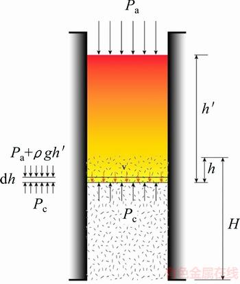
Fig. 1 Scheme of liquid metal infiltration process under slug flow hypothesis (SFH)
Many experiments on liquid metals infiltrating into porous solid preforms indicate that there is a linear relationship between the square of the infiltrated depth and the applied pressure above the threshold pressure [11,16,17]. Such relationship can be analytically derived from Darcy��s law provided that the slug flow hypothesis (SFH) is assumed which implies a constant permeability and a homogeneous filling of the empty space. Also, we assumed that the melt metal stayed in the liquid state throughout the infiltration process. Darcy��s law was used to model the melt alloy infiltration behavior in porous reinforcement preform during the fabrication of metal matrix composites by use of liquid metal infiltration process. It relates the infiltration velocity with the pressure gradient in the infiltration front, viscosity of melt alloy and the permeability of the porous preform as
 (2)
(2)
where v, h, Pa and Pc are parameters as shown in Fig. 1; ��P is the net pressure applied on the infiltration front of the porous preform which is equal to the difference between the sum of applied pressure Pa with gravity pressure ��gh�� from melt alloy and the threshold pressure Pc; �� is the dynamic viscosity of melt alloy which can be valued by experiments; k�� is the permeability of porous preform. It is worthy to mention that the height of melt alloy h�� changes with the infiltration going on because the porous preform can occupy some volume which will cause h�� increasing a little bit. But h�� is considered to be constant for the low volume fraction (10%) of preform in this work.
Integrating Eq. (2) as Eq. (3),
 (3)
(3)
So,
 (4)
(4)
From Eq. (2), we know that Pa and h�� (the amount of melt alloy poured into the mold can be set by us) are given and Pc is unknown in the equation ��P=Pa+��gh��-Pc. Therefore, there are two important unknown variables in Eq. (4), i.e., the threshold pressure Pc and the permeability k��. Unfortunately, they are not easy to be determined directly through experiments [18]. These two unknown parameters can be incorporated into a new parameter ��.
The equation-solving method is proposed in this work to determine the threshold pressure and the permeability based on the relationship between the new parameter �� and these two unknown parameters in Eq. (4). Given the infiltration system, when all the experimental conditions were kept the same, there must be the specific threshold pressure for given preform which has specific permeability. They will not change no matter what the applied pressure is. Based on this assumption, the following equation can be obtained from Eq. (4) which can be successfully solved to get the two unknown variables Pc and k�� only with two independent experiments by applying two different pressure Pa.
 =��
=��
Figure 2 shows the principle of parameters determination by use of two curves obtained experimentally with applying two different pressure Pa. Experimental points can be curve-fitted in the form of Eq. (4). Two coefficients ��1 and ��2 can be obtained which correspond to two coefficients

and
 .
.
Pc and k�� can be solved from the constituted equation set because Pa1 and Pa2 are known.
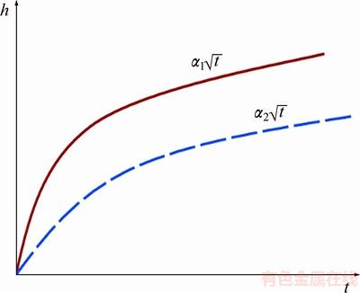
Fig. 2 Illustration of two infiltration curves at two different applied pressures
2.2 Materials
The porous preform was fabricated with Al2O3 short fibers by use of sol-gel method and the volume fraction was kept at 10% [19,20]. The dimensions of preform were 60 mm in height and 40 mm in diameter. The diameter of Al2O3 short fibers was 5-7 ��m, and the length is larger than 50 ��m.
Sn60Pb40 alloy was used as the infiltrating liquid metal with melting point of 183 ��C. Its density is 8.474 g/cm3, the viscosity is 1.68 mPa��s at 350 ��C, and the surface tension is 490 mN/m [21].
2.3 Experimental set-up and methods
Figure 3 shows the principle of the speed-controlled infiltration device. The experimental device included the upper mold and bottom container mainly. The upper mold and bottom container were assembled together. The steel pipe line was connected to the container for vacuuming purpose. The Al2O3 short fiber preform was placed in the upper mold and high temperature glue was used so as to avoid infiltration from the gap formed between preform and mold. Nine K-type thermal couples spaced 6 mm in vertical position were used to monitor the temperature changes of melt alloy in different depth during infiltration (numbered 0-8 from the top to bottom). Nine K-type thermal couples were connected to the thermal couple hub and thermal couple hub was connected to the data collecting system. The tuning valve was opened totally before pouring melting alloy so that the vacuum pressure can be increased from 0 to the set value. After the preparation of all set-up, melting alloy was poured into the upper mold and thermal couples were dipped into the melting alloy. Temperatures from nine thermal couples would increase to the temperature of melting alloy. After 50 s, vacuum pump was turned on and adjusted by use of the tuning valve to the set vacuum pressure. The melting alloy would infiltrate into the preform under vacuum pressure. The thermal couples dipped into the melting alloy left alloy with the infiltration process going on. So, the sharp initial temperature decrease is clearly observed, which is associated with the departure of the melt alloy surface at the position of the recording thermocouple, due to the higher temperature of the melt alloy compared with the surrounding temperature, as illustrated in Fig. 4.
The infiltration front position and time for melt alloy arriving at that position can be obtained from Fig. 4. Different vacuum pressure can cause different infiltration velocities. Two groups of experiments were conducted under two different vacuum pressures which can be used to form an equation set for solving the threshold pressure and permeability as described in the earlier Section 2.1.
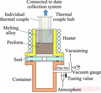
Fig. 3 Illustration of controllable infiltration experiments
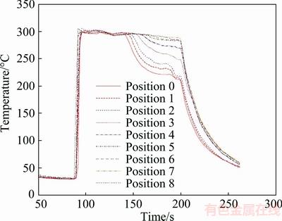
Fig. 4 Temperature variation curves during infiltration at vacuum pressure of 10 kPa
3 Results and discussion
3.1 Temperature variation curves and determination of infiltration front
Figure 4 shows the temperature variation curves of nine thermal couples dipped into the melt tin-lead alloy during the infiltration at the vacuum pressure of 10 kPa. Before the thermal couples were dipped into the melt alloy, temperatures of them were almost the same as the room temperature, i.e., 25 ��C or so. When they were dipped into the melt alloy, the temperature increased suddenly to 300 ��C or so. At this temperature, the melt alloy stayed steadily for about 50 s. Then, the bottom container was vacuumed slowly by tuning the valve gradually. When the vacuum gage said 10 kPa, the melt alloy began to infiltrate into the preform. With the infiltration processing, the thermal couple 0 left the melt alloy, so its temperature began to drop down. We could easily get the time at which the temperature began dropping down. By the same method, we can also get the corresponded time of temperature dropping down for thermal couple 1-8. Figure 4 also shows that the temperature change for thermal couples 0-5 is obvious and that for the other three thermal couples 6-8 is not very obvious. This is caused by the following reason. Thermal couples 0-5 are close to the open mouth of the mold and heat can be easily transferred by air convection which will cause the temperature dropping down obviously. While the thermal couples 6-8 are located at half bottom of the mold, the heat cannot easily carried off by air convection from them. So, their temperature changes were not obvious.
Before dipping into the melt alloy, the relative position between thermal couples was recorded which was 6 mm between thermal couples as stated before. Also, the depth for thermal couple 0 away from the surface of melt alloy was also fixed at 6 mm by pouring fixed amount of melt alloy in the height of 54 mm in every experiment. The infiltration depth and the corresponding infiltration time can be retrieved from Fig. 4, as listed in Table 1 for the experiment with applied pressure of 10 kPa.
Table 1 Infiltration time and corresponding infiltration depth
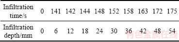
Infiltration must take place from time 0. We took the assumption as shown in Eq. (3), and we fitted the data by using equation  We got two variables ��=8.5 and t0=140 s. It is worth mentioning that thermal couple 0 is 6 mm away from the surface of the melt alloy. So, the time liquid metal reaching the thermal couple 0 is longer than 140 s, as shown in Fig. 4. We plotted the fitting curve and the data listed in Table 1 by shifting the curve to the original point with t0 subtracted from the original infiltration time, as illustrated in Fig. 5.
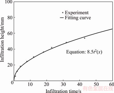
Fig. 5 Relationship between infiltration height and infiltration time obtained from temperature variation curve as shown in Fig. 4 (applied pressure of 10 kPa)
3.2 Determination of permeability and threshold pressure
By using the method introduced in Section 3.1, infiltration curve for pressure of 17 kPa was also obtained which was plotted in the same figure with the curve for pressure of 10 kPa. Fitting curves were also plotted together with experimental points, as shown in Fig. 6. It was shown that pressure increasing can cause high infiltration speed.
From Fig. 6, discrete experimental points can be clearly recorded because the infiltration process has been elongated with controlled vacuum pressure, which means that the infiltration velocity has been slowed down. Data from two experiments were fitted and the two coefficients were obtained, i.e., 11.7 for pressure of 17 kPa and 8.5 for pressure of 10 kPa. From the fitted coefficients, we can get the following equation set:
 (5)
(5)

Fig. 6 Effect of applied pressure on infiltration behavior by experiments
The initial height of melt alloy in the upper mold was 54 mm which would generate 4.5 kPa additional gravity pressure which corresponded to the parameter ��gh��. By solving equation set (5), the threshold pressure and permeability can be obtained to be 6.68 kPa and 7.77��10-22 m2, respectively.
Equations (6) and (7) were used to calculate the theoretical permeability of continuous fiber preform for flow parallel to the fiber axes and for flow perpendicular to the axes extensively [22]:
 (6)
(6)
 (7)
(7)
As for the Al2O3 short fibers preform, introducing the fiber radius of 3 ��m and volume fraction of 0.1 into Eqs. (6) and (7), k// and k��can be obtained to be 28��10-22 and 9.38��10-22 m2, respectively. As for the Al2O3 short fiber preform prepared from the wet pressing method, more fibers distributed in plane and almost there was no parallel fiber with the infiltration direction. So, Eq. (7) is more suitable to the short fiber reinforcement preform.
Now, we can see the permeability for 10% (volume fraction) Al2O3 short fiber preform obtained by the proposed method in this work is close to that calculated by theoretical model, i.e., 7.77��10-22 and 9.38��10-22 m2, respectively. So, the method proposed in the work is reasonable.
3.3 Experimental verification of determined permeability and threshold pressure
The experimentally-determined permeability and threshold pressure in Section 3.2 with the referenced melt alloy viscosity from literature together were introduced into Eq. (3). The final theoretical model for infiltration is
 (8)
(8)
where P��a is the sum of applied pressure and melt alloy gravity pressure, kPa.
By conducting another experiment with applied pressure of 6 kPa and the initial height of 54 mm of melt alloy in the upper mold (corresponding to the gravity pressure of 4.5 kPa), we get the relationship between infiltration height and time as  .
.
The predicted result and experimental result are plotted together in Fig. 7. It is shown that they are matched very well, which indicates that calculated permeability and threshold pressure by use of equation-solving method are reliable.
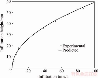
Fig. 7 Verification of proposed model by use of additional experiment
3.4 Prediction of infiltration behavior by determined permeability and threshold pressure
As discussed above, we have obtained the final model for predicting the infiltration behavior of melt Pb-Sn alloy in the 10% Al2O3 preform as Eq. (8).
The relationship between infiltration height and infiltration time is plotted in Fig. 8 for different applied pressures. It is shown that pressure of 90 kPa can make melt Pb-Sn alloy infiltrate into the preform more than 25 mm within only 1 s. In reality, we usually apply far more than 90 kPa for reducing the porosity in the final composite. So, the infiltration speed is very fast at high pressure.
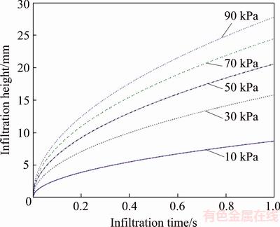
Fig. 8 Prediction for relationship between infiltration height and infiltration time by use of proposed model
The relationship between infiltration height and infiltration time is plotted in Fig. 9 for pressures of 10, 50 and 500 kPa. It is shown that infiltration height can be more than 60 mm within 1 s for pressure of 500 kPa. What��s more, the influence from the threshold pressure is almost vanished for applied pressure of 500 kPa because it is far more than threshold pressure. There is significant difference for predicted curves with or without considering the threshold pressure at low applied pressure.
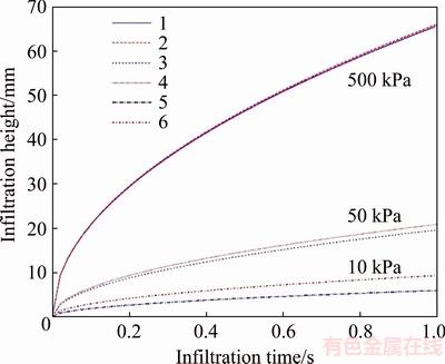
Fig. 9 Comparison between infiltration behavior with (1, 3, 5) and without (2, 4, 6) considering threshold pressure at different applied pressures
4 Conclusions
1) Equation-solving method proposed in this work was successfully used to determine the threshold pressure and permeability for melting alloy infiltration and verified by use of infiltration experiment of Sn60Pb40 alloy in 10% (volume fraction) Al2O3 short fiber preform. The threshold pressure and permeability are determined to be 6.68 kPa and 7.77��10-22 m2, respectively, at last.
2) The infiltration velocity is very fast in the Sn-Pb/Al2O3 composite system. The prediction conducted by use of the determined model shows that pressure of 50 kPa can cause Sn60Pb40 alloy melt to infiltrate into the height of 20 mm or so within 1 s in the preform of 10% (volume fraction) Al2O3 short fiber.
3) The influence from the threshold pressure on the infiltration behavior was investigated and it is found that increasing applied pressure can reduce the effect from threshold pressure. The influence can be ignored when applied pressure reaches 500 kPa.
References
[1] SREE MANU K M, AJAY RAAG L, RAJAN T P D, CHANDRASEKHAR B P. Liquid metal infiltration processing of metallic composites: A critical review [J]. Metallurgical and Materials Transactions B, 2016, 47(5): 2799-2819.
[2] GUAN J T, QI L H, LIU J, ZHOU J M, WEI X L. Threshold pressure and infiltration behavior of liquid metal into fibrous preform [J]. Transactions of Nonferrous Metals Society of China, 2013, 23(11): 3173-3179.
[3] QI L H, SU L Z, ZHOU J M, GUAN J T, HOU X H, LI H J. Infiltration characteristics of liquid AZ91D alloy into short carbon fiber perform [J]. Journal of Alloys and Compounds, 2012, 527: 10-15.
[4] TROJANOVA Z, MATHIS K, LUKAC P, JANECEK M, FARKAS G. Plastic properties of a Mg-Al-Ca alloy reinforced with short Saffil fibers [J]. Metallurgical and Materials Transactions A-Physical Metallurgy and Materials Science A, 2014, 45(1): 29-35.
[5] ZHANG S, ZHU M J, ZHAO X, XIONG D G, WAN H, BAI S X, WANG X D. A pore-scale, two-phase numerical model for describing the infiltration behaviour of SiCp/Al composites [J]. Composites Part A-Applied Science and Manufacturing, 2016, 90: 71-81.
[6] LACOSTE E, MANTAUX O, DANIS M. Numerical simulation of metal matrix composites and polymer matrix composites processing by infiltration: A review [J]. Composites Part A-Applied Science and Manufacturing, 2002, 33: 1605-1614.
[7] YAO Y, CHEN L. Processing of B4C Particulate-reinforced magnesium-matrix composites by metal-assisted melt infiltration technique [J]. Journal of Materials Science & Technology, 2014, 30(7): 661-665.
[8] BAHRAINI M, MOLINA J M, KIDA M, WEBER L, NARCISO J, MORTENSEN A. Measuring and tailoring capillary forces during liquid metal infiltration [J]. Current Opinion in Solid State & Materials Science, 2005, 9(4-5): 196-201.
[9] YAO Y T, JIANG L, FU G F, CHEN L Q. Wear behavior and mechanism of B4C reinforced Mg-matrix composites fabricated by metal-assisted pressureless infiltration technique [J]. Transactions of Nonferrous Metals Society of China, 2015, 25(8): 2543-2548.
[10] KAPTAY G. The threshold pressure of infiltration into fibrous preforms normal to the fibers�� axes [J]. Composites Science and Technology, 2008, 68(1): 228-237.
[11] RODRIGUEZ-GUERRERO A, SANCHEZ S A, NARCISO J, LOUIS E, RODRIGUEZ-REINOSO F. Pressure infiltration of Al- 12 wt.% Si-X (X=Cu, Ti, Mg) alloys into graphite particle performs [J]. Acta Materialia, 2006, 54(7): 1821-1831.
[12] RAVI S, DHARMARAJAN R, MOGHADDAM S. Measurement of capillary radius and contact angle within porous media [J]. Langmuir, 2015, 31(47): 12954-12959.
[13] RICCI E, NOVAKOVIC R. Wetting and surface tension measurements on gold alloys [J]. Gold Bulletin, 2001, 34(2): 41-49.
[14] RODRIGUEZ-GUERRERO A, NARCISO J, LOUIS E, RODRIGUEZ-REINOSO F. Decreasing the infiltration threshold pressure of Al-12 wt% Si into alumina particle compacts by Sn or Pb layers [J]. Composites Science and Technology, 2008, 68(1): 75-79.
[15] EARDLEY E S, FLOWER H M. Infiltration and solidification of commercial purity aluminium matrix composites [J]. Materials Science and Engineering A-Structural Materials Properties Microstructure and Processing, 2003, 359(1-2): 303-312.
[16] LOUIS E, MIRALLES J A, MOLINA J M. High temperature infiltration at low overpressures: Darcys law, the slug-flow hypothesis and percolation [J]. Journal of Materials Science, 2015, 50(4): 1655-1665.
[17] MOLINA J M, TIAN J, NARCISO J, LOUIS E. Fabrication of Al/TiB2 composites through gas pressure infiltration [J]. Journal of Materials Science, 2010, 45(10): 2816-2821.
[18] ZHOU J M, GU X H, YANG F, QI L H. Measuring threshold pressure of melt magnesium infiltrating into Al2O3sf porous preform with fast method [J]. Materials Science Forum, 2014, 783-786: 1609-1614.
[19] ZHANG B F��YANG F��ZHOU J M, QI L H. Preparation of alumina short fiber preform using mold pressing technique in vacuum and its quality [J]. Journal of Shanghai University (Natural Science Edition), 2014, 20(1): 59-67. (in Chinese)
[20] QI Le-hua, XU Rui, SU Li-zheng, ZHOU Ji-ming, GUAN Jun-tao. Dynamic measurement on infiltration process and formation mechanism of infiltration front [J]. Transactions of Nonferrous Metals Society of China, 2010, 20(6): 980-986.
[21] KABAN I, MHIAOUI S, HOYER W, GASSER J G. Surface tension and density of binary lead and lead-free Sn-based solders [J]. Journal of Physics-Condensed Matter, 2005, 17(50): 7867-7873.
[22] MORTENSEN A, MASUR L J, CORNIE J A, FLEMINGS M C. Infiltration of fiberous preforms by a pure metal. 1. Theory [J]. Metallurgical Transactions A-Physical Metallurgy and Materials Science, 1989, 20(11): 2535-2547.
���ڷ�����ⷨȷ��Һ̬�����������յ��ٽ����ѹ��������
�ܼ��������ֻ�
������ҵ��ѧ ����ѧԺ������ 710072
ժ Ҫ�����ڷ�������ԭ�����ȷ�����������ϲ����Ʊ�������2���ؼ�����(�ٽ����ѹ��������)���·�������ƽ����ٶȿɿصĽ���ʵ��װ�ã�����ȷ�����Ͻ�Һ�ڶ��Ԥ�����еĽ�����Ϊ������Pb-Sn�Ͻ���Al2O3Ԥ�����еĽ���Ϊ������2�鲻ͬѹ���½��н���ʵ����ԣ����2�������������ʱ��Ĺ�ϵ���ߣ�ͨ��������Ϸ�ʽ�õ�2����ϲ��������ݴ����������õ�δ֪������������������÷�����ⷽ����õ��ٽ����ѹ�������Բ��������۱���ֵ�dz���������⣬���û�õIJ���Ԥ������ѹ��������Pb-Sn�Ͻ���Al2O3Ԥ�����е�������Ϊ����ʵ�����Ǻ����ã��ɴ���֤�÷����Ŀ����ԡ��÷���Ҳ�������������������ϲ���ϵͳ�ٽ����ѹ�������Բ����IJⶨ��
�ؼ��ʣ����������ϲ��ϣ����ԣ��ٽ����ѹ�����������գ���������
(Edited by Bing YANG)
Foundation item: Project (51575447) supported by the National Natural Science Foundation of China; Project supported by Top University around World Visiting Plan for Young Teacher��s Cultivating in NWPU, China
Corresponding author: Ji-ming ZHOU; Tel: +86-29-88488017; Fax: +86-29-88491982; E-mail: zhoujm@nwpu.edu.cn
DOI: 10.1016/S1003-6326(18)64851-4
Abstract: A new method for determining two key parameters (threshold pressure and permeability) for fabricating metal matrix composites was proposed based on the equation-solving method. An infiltration experimental device was devised to measure the infiltration behavior precisely with controllable infiltration velocity. Two experiments with alloy Pb-Sn infiltrating into Al2O3 preform were conducted independently under two different pressures so as to get two different infiltration curves. Two sets of coefficients which are functions of threshold pressure and permeability can be obtained through curve fitting method. By solving the two-variable equation set, two unknown variables were determined. It is shown that the determined threshold pressure and permeability are very close to the calculated ones and are also verified by another independent infiltration experiment. The proposed method is also feasible to determine the key infiltration parameters for other metal matrix composite systems.
