

J. Cent. South Univ. (2020) 27: 2614-2627
DOI: https://doi.org/10.1007/s11771-020-4486-8

Multi-UAV surveillance implementation under hierarchical dynamic task scheduling architecture
WU Wen-di(���ĵ�)1, WU Yun-long(������)2, 3, LI Jing-hua(���)3,
REN Xiao-guang(��С��)2, 3, SHI Dian-xi(ʷ��ϰ)2, 3, TANG Yu-hua(����)1
1. State Key Laboratory of High Performance Computing (HPCL), College of Computer,
National University of Defense Technology, Changsha 410073, China;
2. Artificial Intelligence Research Center (AIRC), National Innovation Institute of Defense Technology (NIIDT), Beijing 100071, China;
3. Tianjin Artificial Intelligence Innovation Center (TAIIC), Tianjin 300457, China
 Central South University Press and Springer-Verlag GmbH Germany, part of Springer Nature 2020
Abstract:
In this paper, we consider a multi-UAV surveillance scenario where a team of unmanned aerial vehicles (UAVs) synchronously covers an area for monitoring the ground conditions. In this scenario, we adopt the leader-follower control mode and propose a modified Lyapunov guidance vector field (LGVF) approach for improving the precision of surveillance trajectory tracking. Then, in order to adopt to poor communication conditions, we propose a prediction-based synchronization method for keeping the formation consistently. Moreover, in order to adapt the multi-UAV system to dynamic and uncertain environment, this paper proposes a hierarchical dynamic task scheduling architecture. In this architecture, we firstly classify all the algorithms that perform tasks according to their functions, and then modularize the algorithms based on plugin technology. Afterwards, integrating the behavior model and plugin technique, this paper designs a three-layer control flow, which can efficiently achieve dynamic task scheduling. In order to verify the effectiveness of our architecture, we consider a multi-UAV traffic monitoring scenario and design several cases to demonstrate the online adjustment from three levels, respectively.
Key words:
prediction-based synchronization; dynamic task scheduling; hierarchical software architecture��
Cite this article as:
WU Wen-di, WU Yun-long, LI Jing-hua, REN Xiao-guang, SHI Dian-xi, TANG Yu-hua. Multi-UAV surveillance implementation under hierarchical dynamic task scheduling architecture [J]. Journal of Central South University, 2020, 27(9): 2614-2627.
DOI:https://dx.doi.org/https://doi.org/10.1007/s11771-020-4486-81 Introduction
With the rapid development of artificial intelligence and automation technologies, numerous research contributions have been made to the evolution of robotics. Nowadays, various kinds of robots are also playing important roles in our social lives, e.g., data collection [1], field exploration [2]. Compared with the single-robot system, a system consisting of multiple robots can largely improve the task performance by coordination, which is more suitable for challenging tasks and complex environment [3, 4]. In recent years, considerable research contributions have been made to the evolution of multi-robot systems (MRS), and this trend will continue in the coming decades [5]. Among various applications of MRS, surveillance is a typical kind of task which often appears in office floor patrolling [6], outdoor monitoring [7],etc. Compared with other types of robots, unmanned aerial vehicles (UAV) have higher surveillance speed and broader vision, which is more suitable for some outdoor tasks.
In multi-UAV surveillance task, a typical implementation is to keep the motion of all robots consistent [8], which makes the system achieve a better performance. In this condition, the multi- UAV system requires a relatively ideal communication connectivity. However, in realistic communication environment, the wireless channel often experiences path loss, shadowing and multipath fading [9], which largely decreases the channel reliability and makes the communication link unstable. In order to solve this problem, one kind of method is to integrate the communication connectivity optimization into the process of task planning. However, this method may restrict the motion of robots, which degrades the performance of task execution [10]. The other methods may allow a temporary communication interruption. When the communication connectivity is broken, the robots can adopt predefined rules to make the robots rendezvous near enough to communicate with each other [11]. In some situations, there may be no predefined rules, where the robot losing connectivity will use target searching method to actively approach the robot [12] or predict the motion of other robots [13]. In multi-UAV surveillance scenario, each UAV needs to prioritize the task execution and is not allowed to move to other places for maintaining communication connectivity, so the prediction-based method may be more suitable.
In practical surveillance scenario, the environment is dynamic and full of uncertainty, which makes a single algorithm cannot cope with all possible situations in the environment. In addition, an algorithm that can handle all situations tends to be more complex. Therefore, a feasible solution is to specialize the function of each algorithm and design a software architecture that can support dynamical task scheduling for improving the robustness of the system in surveillance tasks.
BRUNO et al [14] recommended that robot architecture design should meet the features of modularity and hierarchy. For the modularity, it firstly needs to classify the related algorithms according to their functions. The classic robot architectures decompose the functions of robots into three stages: sensing, planning, and executing, which is also called the ��sense-plan-act�� (SPA) paradigm [14, 15]. Although the SPA paradigm is currently widely used in robotics research, the paradigm still faces problems. Firstly, if the plan stage consumes too much time, it will block the execution of the act stage, which will make the control process unstable. Secondly, in some cases, the act stage requires the sensing information which is blocked by the plan stage. The above two problems show that the three stages should not be sequenced and coupled together, which needs to be considered in architecture design. For the techniques to modularize the algorithms, plugin is an effective way to encapsulate algorithms [16]. With well-defined interfaces, the plugins can be developed independently from specific applications. Currently, plugin techniques are widely used in the development of robot functions [17, 18], and some plugin-based architectures are produced, e.g., OpenRAVE [19], OpenMRH [20].
For the hierarchy, the decomposition of robotic systems can be decomposed from the dimensions of time, space, task, etc., but which dimension is better does not form a consistent view [14]. In this paper, we prefer a hierarchical mechanism based on task dimensions. In terms of implementation, the plugins can be used as dynamically loaded modules to support dynamic scheduling. However, the plugin itself cannot be hierarchically decomposed based on task abstraction, which needs to be combined with other structures. A series of methods supporting dynamic scheduling are widely used in robot control, such as finite state machine, decision tree [21], subsumption architecture [22], behavior tree [23]. The behavior tree model has a universal representation ability and can accommodate the above three models, which are currently widely used in robot motion control [21]. According to the above discussion, integrating plugin technology and behavior tree model is a feasible solution for implementing hierarchical dynamic task scheduling. And, as far as we know, there is no research detailedly discussing this mechanism.
Against the above background, this paper considers solving a multi-UAV surveillance scenario where a leader UAV and multiple follower UAVs cover a ground area in dynamical and uncertain environment. All follower UAVs need to keep the consistent phase angles with the leader UAV. In order to adapt to practical surveillance environment, we propose a hierarchical dynamic task scheduling architecture for responding to changes in environmental conditions. The main contributions of this paper are summarized as follows:
1) We propose a modified Lyapunov guidance vector field (LGVF) approach which uses a polynomial correction to improve the surveillance trajectory tracking precision for the leader and follower UAVs.
2) In order to improve the robustness of the system in poor communication environment, we propose a prediction-based synchronization method which can tolerate the intermittent communication.
3) We propose a hierarchical dynamic task scheduling architecture for making the multi-UAV system adapt to dynamical and uncertain surveillance environment. The architecture modularizes the classified algorithms based on the plugin technology, and integrates the behavior tree model to realize the dynamic scheduling of the modularized algorithms.
4) In order to verify the effectiveness of the algorithms and software architecture proposed in this paper, we implement the surveillance scenario in ROS and Gazebo environment [24]. The simulation results demonstrate that the techniques proposed in this paper can give a useful reference for deploying UAVs to execute the surveillance task.
The rest of this paper is organized as follows. Firstly, the details of the surveillance algorithms are introduced in Section 2. Section 3 demonstrates the software architecture including structure design, algorithm interface abstraction, control flow, etc. Furthermore, in Section 4, we consider a traffic monitoring scenario and verify the effectiveness of the architecture with several specific cases.
2 Multi-UAV surveillance algorithms
Motivated by Ref. [8], we consider a similar scenario where a team of UAVs is responsible for covering a ground area, as shown in Figure 1. In this scenario, each UAV is allocated a virtual point which it flies around. For the way of formation control, we adopt the leader-follower control mode where the UAVs acting as followers need to be consistent with the leader UAV. In this scenario, the follower UAVs may subscribe the state of the leader UAV and keep the same phase angle.
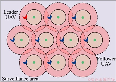
Figure 1 Multi-UAV surveillance scenario
2.1 Area coverage
In the surveillance task, the first thing to do is to deploy virtual points, which determines the number of UAVs to be deployed. Differing from Ref. [8], the virtual points are preplanned and may not change during the whole surveillance process, unless there are other tasks that need to be performed, such as target tracking. Therefore, the above problem can be translated into how to deploy virtual points according to the sensing capabilities of the UAVs and the surveillance area to minimize the number of UAVs to be deployed. For this problem, the solutions to calculate the optimal sensor deployment in mobile wireless sensor networks (WSNs) can provide a reference. As shown in Figure 2, the virtual point is seen as the sensor, and the desired flight radius rd of the UAV is half of the sensing radius rs, i.e., rs=2rd. In this paper, the area coverage may adopt the deployment schemes in Ref.[25].
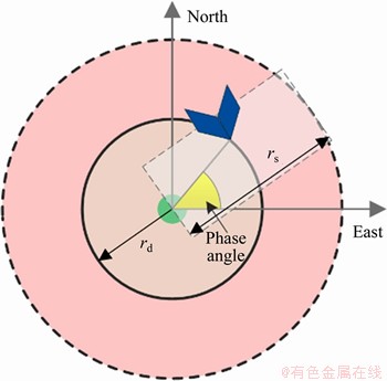
Figure 2 Relationship between flight radius and sensing radius
2.2 Trajectory tracking
In order to make the UAV can fly around the preplanned virtual point, an effective way is to use a velocity potential field to guide the motion of UAV [8]. The Lyapunov guidance vector field (LGVF) approach is a widely used method that can provide a global stability for the guidance of unmanned aircraft [26]. However, in our scenario, we need to make the UAVs track the trajectory with the desired radius precisely. The original LGVF approach needs to be modified to fit for our requirements.
Let p=[pn, pe, h]T denote the position vector of the UAV in north, east and height directions. As shown in Ref. [8], we assume the flight height of the UAV is fixed and the wind speed is zero. The kinematics of the UAV can be modeled as Eq. (1):
 (1)
(1)
where v and �� denote the airspeed and heading of the UAV, respectively. The position vector can be simplified as p=[pn, pe]T.
In the absence of wind, the course angle �� is equal to ��. In the LGVF approach, the desired course angle ��d can be calculated with Eq. (2):
 (2)
(2)
The function atan2 returns the arctangent in the range of (-��, ��]. and
and  denote the desired airspeed in the east and north directions, respectively.
 is the position vector relative to its corresponding virtual point. If the virtual point locates at
 then pr=p-pv.
 is the distance between the UAV and the virtual point.
In order to make the UAV precisely track the orbit trajectory, in this paper, we integrate the commanded airspeed vc into the adjustment of ��d, as shown in Eq. (3). ��c denotes the commanded course angle to the controller of the UAV; km,i represents the fitting parameter; ���� is the course angle correction; M is the fitting precision.
 (3)
(3)
Furthermore, we need to adjust ��c to ensure 
2.3 Phase angle synchronization
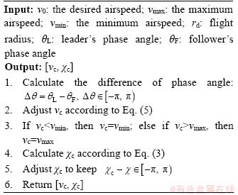
When performing the surveillance task, each UAV will circle around the assigned virtual point. In order to make the follower UAVs and leader UAV have the same phase angles, adjusting the linear velocity is a straightforward method. When the phase angle of the follower UAV is behind the leader UAV, the follower UAV increases its airspeed to maintain the desired phase angle while maintaining the desired flight radius. On the contrary, it will reduce its airspeed. In order to quantify the degree of synchronization between the follower UAV and the leader UAV, this paper defines the phase angle difference ����, as shown in Eq. (4):
 (4)
(4)
where ��L and ��F denote the phase angles of the leader UAV and follower UAV, respectively. When ���ȡ�0, the follower UAV will catch up at a higher airspeed. If ����>0, the follower UAV will wait at a lower airspeed. The command vc is calculated according to Eq. (5), where v0 is the expected linear velocity, vmax and vmin are the maximum and minimum velocity of the UAV, respectively. k is a constant that controls the magnitude according to ����.
 (5)
(5)
Considering the velocity limitation, we may restrict vc according to Eq. (6):
 (6)
(6)
The above process can be described by Algorithm 1.
Algorithm 1
2.4 Phase angle prediction
In practical surveillance environment, the communication link may be not continuously connected, which makes the state of the leader UAV not always be received in time. Therefore, we propose a prediction-based synchronization method to try to make the follower UAVs predict the phase angle of the leader UAV. Considering that all UAVs fly around their virtual points and maintain a uniform airspeed after synchronization, the follower UAVs can predict the phase angle of the leader UAV by using the its state data at the previous moment.
The specific process can be represented by Algorithm 2.  is the cached position vector of the leader UAV. When a new state message from the leader UAV is received, will be updated.
  is the latest updated phase angle of the leader UAV, and
  is the corresponding update time. ��L denotes the predicted angular velocity of the leader UAV. The output of the algorithm is the predicted phase angle ��L of the leader UAV.
Algorithm 2
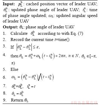
In the beginning of the algorithm, a temporary phase angle  is calculated according to the state of the UAV
  with Eq. (7):
 (7)
(7)
If  (�� is a small positive value), it can be determined that the state of the leader UAV is not currently received and the phase angle of the leader UAV needs to be predicted (line 3). Otherwise, ��L,and will be updated.
3 Architecture design
In practical surveillance environment, there are many situations that are unpredictable, which requires the UAVs to respond to unexpected situations. Against this requirement, this paper designs the hierarchical software framework and the details are introduced in this section.
3.1 General structure
This architecture organizes all functional modules into three layers. The top layer of the architecture is used to manage the plugins for achieving specific tasks. Each task corresponds to a specific application and contains a complete behavior chain which includes a sense plugin, a plan plugin, and an act plugin. All plugins are attached to a bus and dynamically scheduled by a module named task scheduler. In order to overcome the drawbacks of the SPA diagram, the three kinds of plugins can communicate with each other arbitrarily. The task scheduler loads and unloads plugins according to the commands from the control center or its intelligent judgement. The structure of this layer is shown in Figure 3.
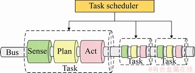
Figure 3 Structure of top layer
The middle layer refers to the implementation of plugins. The interior structure of a plan plugin is shown in Figure 4, which contains six kinds of modules: plugin base, behavior tree, plugin example, performance evaluation, and interfaces. Plugin base is the base class inherited by plugin example, which may provide the basic functions including algorithm dynamic management, general operations, etc. Plugin example is responsible for integrating all the functional modules into the plugin. Its implementation is based on the data structure of the behavior tree model and creates a behavior tree instance for managing and scheduling functional modules. In behavior tree, the control nodes (sequence, fallback, and parallel nodes) are responsible for controlling the calling process of execution nodes (action and condition nodes), which implement specific algorithm functions. In the action and condition nodes, the algorithms for achieving specific tasks are dynamically loaded from the corresponding action or condition algorithm libraries. All algorithms follow a predefined interface specification which will be detailedly discussed in Section 3.2. A well-defined interface may help to decouple the dependency between plugin example and a specific algorithm. In addition to the action and condition algorithms, it can also include tool algorithm libraries that can be utilized by all plugins, e.g., performance analysis, data processing, scientific calculation, communication, etc. Performance evaluation module will judge the situation of the environment in real time, and trigger the algorithm switching.
3.2 Algorithm interface
In order to make the algorithm easily be used by users and designed by developers, it is necessary to abstract unified algorithm interface for each stage of the SPA diagram, i.e., the metadata standard for each algorithm library. For each algorithm interface, it may include two main parts: the function name and the arguments. An easy way to define the function name is to follow their stage names, e.g., sense(), plan(), and act(). Compared with the function name, the arguments of each interface function are more difficult to be unified. There is a big difference in the structure of the input and output between different algorithms, especially in different stages. For example, the algorithms in the sense stage mainly focus on processing the input data from the sensors equipped on UAVs, e.g., cameras, lidars, GPS, IMU, etc. However, the output data of the sensors have various types, which makes it is difficult to use a unified argument to describe them. Moreover, compared with the functions in the sense stage, the arguments of the algorithms in the plan and act stages may be in a low dimension. In order to maximize the flexibility and generalizability of the argument design, we use a structure of unified_message to express the structure of the arguments for each stage of the SPA diagram, as shown in Figure 5.
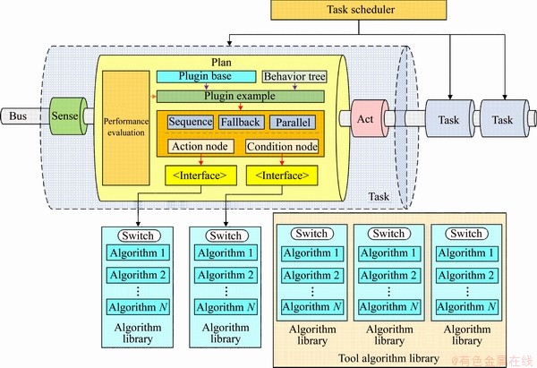
Figure 4 Interior structure of specific plugin
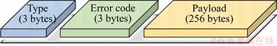
Figure 5 Structure of unified_message
The unified_message includes three segments: type, error code, and payload. The type is a 3-byte segment that can be customized by users according to specific tasks. The allowed types of messages are up to more than 16 million. The segment of error code indicates the abnormal conditions which may trigger the process of algorithm dynamically switching. The detailed algorithm switching process will be discussed in detail in the next section. The payload contains the details of the message whose structure is specified by the type segment. Based on the above analysis, we may define the algorithm interface with a unified form. Figure 6 demonstrates an algorithm interface example for the sense stage. For each algorithm interface, it contains two arguments whose types are unified_message, and the input argument of the interface is decorated by the key word ��const��.
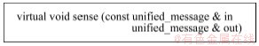
Figure 6 Algorithm interface example for sense stage
Furthermore, for each algorithm, there are also some parameters that should be initialized before the running of the algorithm. Meanwhile, different algorithms often have different structural parameters. In order to facilitate the unified interface design for the process of parameter setting, we may reuse the unified_message to define the interface. As shown in Figure 7, the interface function init() is used to define the way to set parameters for each algorithm. The argument of param contains the parameters to be used, which is capsulated into the unified_message and adopt the type segment to distinguish the function of its following payload segment. In general, the unified_message can define two main kinds of messages, one is the runtime input of the algorithm, and the other is the parameter configuration of the algorithm.

Figure 7 Definition of parameter configuration interface
3.3 Control flow design
In order to ensure that the task can be executed successfully, we also need to design a flexible and efficient control flow to meet the dynamic situations in environment. In order to cope with the dynamic changes in external conditions, we design a three-level control flow. According to the focus of each level, we define the levels as task level, behavior level, and function level, respectively. In Figure 8, we give a control flow diagram that follows the definition above. In the first step of the control flow, it needs to load appropriate plugins to fulfill the task requirements. Then, we can build the behavior model and select the initial algorithms for each action (condition) node in the behavior tree.
The following parts of the control flow in Figure 8 are the main loop which is managed according to the three levels. In order to adapt to the dynamic requirements in environment, all the three levels of the control flow can support the online adjustment. In the task level, the main job is adopting the task scheduler to dynamically select appropriate plugins according to the task requirements. This procedure is only performed when the mission of the UAV is changed. The remaining two levels are both happen inside plugins. In the behavior level, it needs to judge if the behavior model in the plugin should be adjusted. When a more serious situation occurs, e.g., a major adjustment for the task, the behavior tree model may be reconstructed. In the function level, it mainly refers to the algorithm switching process. Compared with the behavior level, the operations in this level are used to handle the slighter changes happen inside UAVs or caused by the environment. In the whole loop, only the procedure of the main control flow with the behavior tree is necessary, the other operations are optionally executed according to the conditions of the UAV and environment.
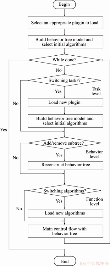
Figure 8 General block diagram of control flow
In the control flow, the behavior tree model is the main part which manages the resources of the SPA diagram and ensures its evolution. In Figure 9, we give a behavior tree example to demonstrate the support for dynamical task scheduling. In Figure 9, Node 1 denotes a sequence node attached to the whole behavior tree. Nodes 2, 3 and 4 are responsible for managing the subtrees.
In the behavior level, the plugin can adjust the control flow by adding or removing subtrees. As shown in Figure 9, the subtrees with the root Node 15 can be dynamically added. This operation may involve a relatively large change of the whole behavior tree, which often corresponds to the hardware error or a major adjustment for the task. On the other hand, it can also directly make use of the condition nodes of the behavior tree to support the online adjustment. If the current status of the UAV cannot fulfill the condition node, it may change to execute the candidate action nodes. An example is shown with Nodes 6 and 11 in Figure 9. If the condition Node 10 returns success, Node 11 that contains two action nodes will be executed; otherwise, action in Node 6 is to be executed. In the behavior level, the condition nodes are mainly used to denote the hardware status of the UAV, e.g., battery level. When the battery level is lower than a certain value, it performs a subtree; otherwise, it executes another subtree.
In dynamic environment, a key capability that a task UAV should own is dynamically selecting the MRS-related algorithms according to its surroundings. Therefore, in the function level, when the performance evaluation module finds that the equipped algorithm does not fit for the current situations, a new algorithm in the libraries will be selected immediately to replace the current algorithm. Moreover, the algorithm switching can also be triggered by other action nodes, especially when they are under the same sequence node. Therefore, we involve two global buffers (input and output) whose types are unified_message, as shown in Figure 10. The input buffer is used to store the required data of the algorithm, and the calculated results are saved in the output buffer. In the next time step (t=T+1), the data in the input buffer will be filled with the output buffer. In this process, both previous action node (Node 13) and the performance evaluation node can write the error code in the updated input buffer, and the later action node (Node 14) may switch algorithms according to the error code.
4 Experiment results
This section presents our experiments to verify the effectiveness of the methods and the software architecture proposed in Sections 2 and 3, respectively.
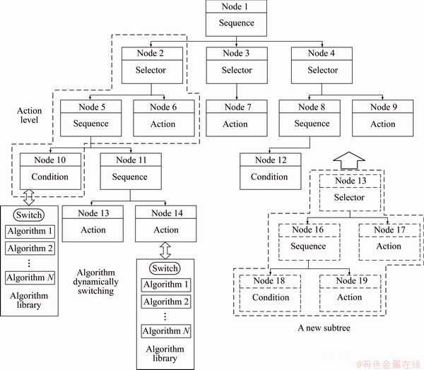
Figure 9 Part of behavior tree used to demonstrate algorithm dynamically switching and subtree adding process
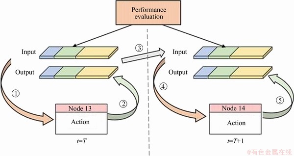
Figure 10 Data sharing between action nodes
4.1 Parameter fitting and verifying
In this subsection, we will verify the usability of our proposed modified LGVF approach. Before the testing, we need to firstly fit the parameters of ���� in Eq. (3). In order to obtain the sample data, in each sampling period, we may fix rd and rc, then modify ���� to achieve r=rd. We assume M=2 and fit the parameters with the sample data, the fitting curve is shown in Figure 11. The fitted parameters are k0,0=-0.1569, k1,0=-0.006063, k1,1=0.0862, k2,0=0.0001031, k2,1=-0.0009796, k2,2=0.0009796 and the corresponding root mean squared error is 0.0137.
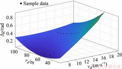
Figure 11 Fitting curve with sample data
The sample data are just a small part of the whole domain. In order to test the accuracy of the fitted model for the unsampled settings, we calculate the flight radius difference ��r=r-rd by sampling vc in [7, 20] every 1 m/s and rd in [30, 70] every 5 m. The error ratio ��r/rd of the original and the modified LGVF approaches is shown in Figures 12(a) and (b), respectively. From Figure 12, we can apparently see that modified LGVF approach can make the UAV more precisely follow the desired flight radius rd than the origin LGVF approach.
4.2 Phase angle synchronization in poor communication conditions
In order to test the effectiveness of our proposed prediction-based synchronization method, we consider a scenario where five UAVs execute the surveillance task. In this scenario, UAV 4 is the leader UAV and other UAVs are followers. For simulating the communication environment, we adopt the packet error rate (PER) model proposed in Ref. [27], where the per-hop PER �� in the transmission mode n between UAV i and UAV j is calculated by Eq. (8):
 (8)
(8)
In Eq. (8), ��i,j denotes the received signal-to- noise ratio (SNR) which is expressed as 
 The channel coefficient hi,j
captures the effect of the small-scale fading, and di,j is the distance between UAVi and UAVj. �� and B represent the pathloss exponent and channel bandwidth, respectively, as well as the power spectral density N0 of the additive white Gaussian noise (AWGN). an, gn, ��pn are transmission-mode- dependent parameters with respect to mode n, respectively. In this simulation, we adopt the settings in mode n=2 and compare the phase angle difference between the leader UAV (UAV 4) and each follower UAV in the non-prediction method (Figures 13(a) and (d)) and the prediction-based method (Figures 13(e) and (h)), respectively. As time goes on, the prediction-based method can make the final phase angle of the follower UAVs and leader UAV basically the same. However, due to the impact of packet loss, the non-prediction method cannot achieve phase angle synchronization, especially for the UAV 1 and UAV 3.
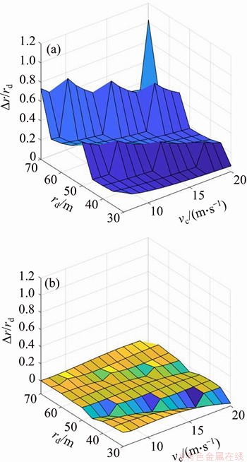
Figure 12 Flight radius error comparison between original and modified LGVF approaches
4.3 Dynamic task scheduling with hierarchical software architecture
This section may verify the functionality of the control flow against to the dynamic situations in surveillance environment. In this subsection, we consider a complete multi-UAV traffic monitoring scenario in Gazebo and involve the communication environment simulation as shown in Section 4.2. In the beginning, five UAVs take off and execute the surveillance task in the specific area. Due to the poor communication environment, the follower UAVs cannot receive the state information of the leader UAV (UAV 4) in time, making the entire UAV formation unable to synchronize, as shown in Figure 14(a). In this condition, the performance evaluation module will find this abnormal condition in function level, and suggest the control flow to switch to a new prediction-based sense algorithm proposed in Section 2.4. Figure 14(b) demonstrates the scenario where the sense algorithm is switched. We may see that the switched algorithm can work well and make the follower UAVs and the leader UAV synchronized.
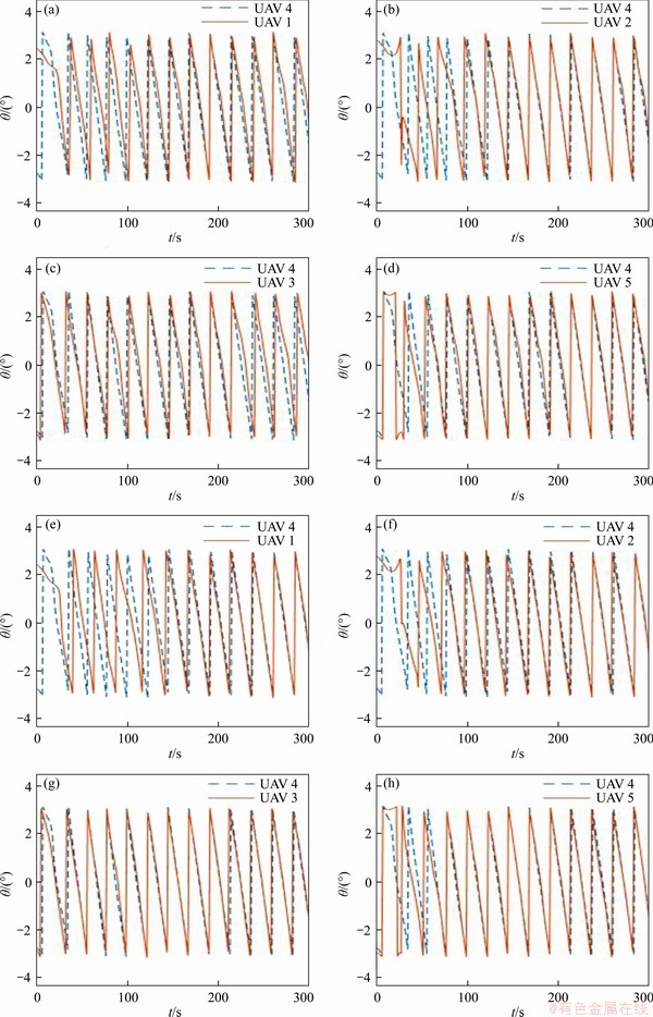
Figure 13 Phase angle difference with non-prediction method between UAV 4 versus UAV 1 (a), UAV 2 (b), UAV 3 (c), UAV 5 (d); Phase angle difference with prediction-based method between UAV 4 versus UAV 1 (e), UAV 2 (f), UAV 3 (g), UAV 5 (h)
Considering that the battery resource loaded in each UAV is limited, we need to ensure that the UAVs can safely return to the landing area before the power is exhausted. By adopting the behavior tree model, we can set a backup action node which loads the return algorithm, and its triggering is controlled by a condition node. When the remaining battery energy is larger than a predefined threshold value, the UAV may perform the surveillance task as usual. However, as soon as the remaining battery energy of the UAV is less than the predefined value, the condition node will activate the action node that loads the return algorithm and terminate the current action. Figure 14(c) demonstrates the above situation, and UAV 3 that has low battery energy will leave the surveillance area and return to the landing area.
Moreover, when traffic conditions are abnormal, the task scheduler will autonomously select a UAV (UAV 5) to investigate the situation, meanwhile other UAVs are still executing the surveillance task. In order to fulfill the requirements for the above task settings, firstly the task scheduler will load new task for UAV 5 for executing investigating tasks instead of surveillance, as shown in Figure 14(d).
5 Conclusions
In order to make the UAV precisely track the surveillance trajectory, we integrated the commanded airspeed into the course angle adjustment of the UAV and proposed a modified LGVF approach which can largely decrease the difference between the desired flight radius and actual radius. Then, for coping with the poor communication conditions, we involved a prediction-based synchronization method where each follower UAV predicts the phase angle of the leader UAV with a uniform angular velocity assumption. Furthermore, in order to support dynamic task scheduling for multi-UAV system, we proposed a hierarchical architecture and introduced its structure design, algorithm interface and control flow. The simulation results showed that our methods can effectively help the UAVs to implement the precisely trajectory tracking and tackle the poor communication conditions. Finally, we implemented the surveillance task in Gazebo simulation environment, and the results demonstrated that the software architecture can support for coping with the dynamic changes during the task execution.
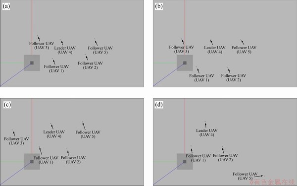
Figure 14 Surveillance task simulated in Gazebo environment
Contributors
The overarching research goals were developed by WU Wen-di, WU Yun-long, REN Xiao-guang and TANG Yu-hua. WU Wen-di and WU Yun-long conducted the literature review and wrote the first draft of the manuscript. LI Jing-hua analyzed the calculated results. SHI Dian-xi edited the draft of manuscript.
Conflict of interest
WU Wen-di, WU Yun-long, LI Jing-hua, REN Xiao-guang, SHI Dian-xi, and TANG Yu-hua declare that they have no conflict of interest.
References
[1] YUAN Yan, YASAMIN M. To go or not to go: on energy-aware and communication-aware robotic operation [J]. IEEE Transactions on Control of Network Systems, 2014, 1(3): 218-231. DOI: 10.1109/TCNS.2014.2337971.
[2] KYLE C, RYAN S, SOO-HYUN Y, ZHANG Ya-wei, GEOFFREY H. Multi-UAV exploration with limited communication and battery [C]// IEEE International Conference on Robotics and Automation. IEEE, 2015: 2230-2235. DOI: 10.1109/ICRA.2015.7139494.
[3] HUANG Wan-rong, WANG Yan-zhen, YI Xiao-dong, YANG Xue-jun. Distributed coordination with connectivity maintenance for nonholonomic robots [J]. Computer Animation and Virtual Worlds, 2018, 29(3, 4): e1833. DOI: 10.1002/cav.1833.
[4] CAI Zhong-xuan, CHANG Xue-feng, WANG Yan-zhen, YI Xiao-dong, YANG Xue-jun. Distributed control for flocking and group maneuvering of nonholonomic agents [J]. Computer Animation and Virtual Worlds, 2017, 28(3, 4): e1777. DOI: 10.1002/cav.1777.
[5] YANG Guang-zhong, JIM B, PIERRE E, PEER F, LUCIANO F, ROBERT F, NEIL J, VIJAY K, MARCIA M, ROBERT M, BRADLEY J, BRIAN S, MARIAROSARIA T, RUSSELL T, MANUELA V, WANG Zhong-lin, ROBERT W. The grand challenges of science robotics [J]. Science Robotics, 2018, 3(14): eaar7650. DOI: 10.1126/scirobotics. aar7650.
[6] MAGNUS L, KARL H. Using robot mobility to exploit multipath fading [J]. IEEE Wireless Communications, 2009, 16(1): 30-37. DOI: 10.1109/MWC.2009.4804366.
[7] WU Yun-long, ZHANG Bo, YANG Shao-shi, YI Xiao-dong, YANG Xue-jun. Energy-efficient joint communication- motion planning for relay-assisted wireless robot surveillance [C]// IEEE Conference on Computer Communications. IEEE, 2017. DOI: 10.1109/INFOCOM. 2017.8057072.
[8] MAJA V, MEYSAM B, GREGOIRE H, DARIO F. Distributed formation control of fixed wing micro aerial vehicles for area coverage [C]// IEEE/RSJ International Conference on Intelligent Robots and Systems. IEEE, 2015. DOI: 10.1109/IROS.2015.7353444.
[9] MEHRZAD M, YASAMIN M. On the spatial predictability of communication channels [J]. IEEE Transactions on Wireless Communications, 2012, 11(3): 964-978. DOI: 10.1109/TWC.2012.012712.101835.
[10] YIANNIS K, MICHAEL M. Distributed intermittent communication control of mobile robot networks under time-critical dynamic tasks [C]// IEEE International Conference on Robotics and Automation. IEEE, 2018. DOI: 10.1109/ICRA.2018.8460570.
[11] BRIANA L, SHAMEKA D, JULIAN D, MONICA A. Using rendezvous to overcome communication limitations in multirobot exploration [C]// IEEE International Conference on Systems, Man, and Cybernetics. IEEE, 2011. DOI: 10.1109/ ICSMC.2011.6084037.
[12] ISAAC V, RODERICH G, ANDREAS K. Re-establishing communication in teams of mobile robots [C]// IEEE/RSJ International Conference on Intelligent Robots and Systems. IEEE, 2018. DOI: 10.1109/IROS.2018.8594460.
[13] GRADTY W, BRIAN G, PAUL D, JAMES M R, EVANGELOS A T. Best response model predictive control for agile interactions between autonomous ground vehicles [C]// IEEE International Conference on Robotics and Automation. IEEE, 2018. DOI: 10.1109/ICRA.2018.846 2831.
[14] BRUNO S, OUSSAMA K. Springer handbook of robotics [M]. Springer, 2016. DOI: 10.1007/978-3-540-30301-5.
[15] JUAN R, LUO Shuang-qi, ZHU Ding-qiao, DU Yun-long, LIN Hong-bin, HUANG Zheng-jie, KUANG Wen-wei, KENSUKE H. Online robot introspection via wrench-based action grammars [C]// IEEE/RSJ International Conference on Intelligent Robots and Systems. IEEE, 2017: 5429-5436. DOI: 10.1109/IROS.2017.8206438.
[16] YANG Xue-jun, DAI Hua-dong, YI Xiao-dong, WANG Yan-zhen, YANG Shao-wu, ZHANG Bo, WANG Zhi-yuan, ZHOU Yun, PENG Xue-feng. micros: A morphable, intelligent and collective robot operating system [J]. Robotics and Biomimetics, 2016, 3(1): 21. DOI: 10.1186/ s40638-016-0054-y.
[17] ANIS K, HACHEMI B, IMEN C, SAHAR T, ADEL A, MOHAMED S, MARAM M, OMAR C, YASIR J. Integration of global path planners in ROS [J]. Robot Path Planning and Cooperation, 2018: 83-102. DOI: 10.1007/ 978-3-319-77042-0_4.
[18] KENTA T, TOSHINNORI A, VALERI K, FLORENTIN S. Simulation environment for mobile robots testing using ros and gazebo [C]// 20th International Conference on System Theory, Control and Computing. 2016: 96-101. DOI: 10.1109/ICSTCC.2016.7790647.
[19] ROSEN D, JAMES K. OpenRAVE: A planning architecture for autonomous robotics [R]. Rep. CMU-RI-TR-08-34, 2008.
[20] FILIPPO S, KRISTIN Y P. OpenMRH: A modular robotic hand generator plugin for OpenRAVE [C]// IEEE International Conference on Robotics and Biomimetics. IEEE, 2015: 1-6. DOI: 10.1109/ROBIO.2015.7407010.
[21] KERSTIN D, CHRYSTOPHER L N. Imitation in animals and artifacts [M]. MIT Press, 2002. DOI: 10.1108/ k.2003.06732gae.004.
[22] RODNEY A B. A robust layered control system for a mobile robot [J]. IEEE Journal on Robotics and Automation, 1986, 2(1): 14-23. DOI: 10.1109/JRA.1986.1087032.
[23] MICHELEC, PETTERO. How behavior trees modularize hybrid control systems and generalize sequential behavior compositions, the subsumption architecture, and decision trees [J]. IEEE Transactions on Robotics, 2016: 33(2): 372-389. DOI: 10.1109/TRO.2016.2633567.
[24] MORGAN Q, KEN C, BRIAN G, JOSH F, TULLY F, JEREMY L, ROB W, ANDREW N. ROS: An open-source robot operating system [C]// ICRA Workshop on Open Source Software, 2009.
[25] WANG Y C, TSENG Y C. Distributed deployment schemes for mobile wireless sensor networks to ensure multilevel coverage [J]. IEEE Transactions on Parallel and Distributed Systems, 2008, 19(9): 1280-1294. DOI: 10.1109/TPDS.2007.70808.
[26] ERIC W F, DALE A L, CORY D, JACK E, WILLIAM J P. Lyapunov guidance vector fields for unmanned aircraft applications [C]// American Control Conference. IEEE, 2007. DOI: 10.1109/ACC.2007.4282974.
[27] LIU Qing-wen, ZHOU Sheng-li, GEORGIOS B. Cross-layer combining of adaptive modulation and coding with truncated ARQ over wireless links [J]. IEEE Transactions on Wireless Communications, 2004, 3(5): 1746-1755. DOI: 10.1109/ TWC.2004.833474.
(Edited by ZHENG Yu-tong)
���ĵ���
���ڲ��ʽ��̬������ȼܹ��µĶ����˻�Ѳ��ʵ��
ժҪ�����Ŀ�����һ�������˻�Ѳ�ߵij������ڸó����У�һ�����˻�ͬ����һƬ����������и���Ѳ�ߡ������캽��-�����߿���ģʽ���������һ�ָĽ���������ŵ����������������߹켣���ٵľ��ȡ�Ϊ����Ӧͨ�������������������һ�ֻ���Ԥ���ͬ�����������ֱ�ӵ�һ���ԡ����⣬Ϊ��ʹ�����˻�ϵͳ�ܹ���Ӧ��̬�Ͳ�ȷ�������������һ�ֲ��ʽ��̬������ȼܹ����ڸüܹ��У����ȶ�����ִ��������㷨���书�ܽ��з��࣬Ȼ����ڲ���������㷨����ģ�黯��ͨ�������Ϊģ�ͺͲ����������������������������Чʵ������Ķ�̬���ȡ�Ϊ����֤������ܹ�����Ч�ԣ�������һ�������˻���ͨ���ӳ����������ʵ����������������չʾ��̬������ȵ�Ч����
�ؼ��ʣ�����Ԥ���ͬ����������̬������ȣ����ʽ�����ܹ�
Foundation item: Project(2017YFB1301104) supported by the National Key Research and Development Program of China; Projects(61906212, 61802426) supported by the National Natural Science Foundation of China
Received date: 2019-12-10; Accepted date: 2020-05-27
Corresponding author: WU Yun-long, PhD, Assistant Professor; E-mail: ylwu1988@nudt.edu.cn; ORCID: https://orcid.org/0000-0002- 6911-954X; REN Xiao-guang, PhD, Associate Professor; E-mail: rxg_nudt@126.com; ORCID: https://orcid. org/0000-0002-8048-6762
Abstract: In this paper, we consider a multi-UAV surveillance scenario where a team of unmanned aerial vehicles (UAVs) synchronously covers an area for monitoring the ground conditions. In this scenario, we adopt the leader-follower control mode and propose a modified Lyapunov guidance vector field (LGVF) approach for improving the precision of surveillance trajectory tracking. Then, in order to adopt to poor communication conditions, we propose a prediction-based synchronization method for keeping the formation consistently. Moreover, in order to adapt the multi-UAV system to dynamic and uncertain environment, this paper proposes a hierarchical dynamic task scheduling architecture. In this architecture, we firstly classify all the algorithms that perform tasks according to their functions, and then modularize the algorithms based on plugin technology. Afterwards, integrating the behavior model and plugin technique, this paper designs a three-layer control flow, which can efficiently achieve dynamic task scheduling. In order to verify the effectiveness of our architecture, we consider a multi-UAV traffic monitoring scenario and design several cases to demonstrate the online adjustment from three levels, respectively.
