
Article ID: 1003-6326(2005)05-1014-07
Preparation of composite electroheat carbon film
XIA Jin-tong(�Ľ�ͯ), TU Chuan-jun(Ϳ����),
LI Yan(�� ��), HU Li-min(������), DENG Jiu-hua(�˾û�)
(College of Materials Science and Engineering, Hunan University, Changsha 410082, China)
Abstract:
A kind of conductive and heating unit, which can reach a high surface electroheat temperature at a low voltage, was developed in view of the traditional electroheat coating which has a low surface electroheat temperature and an insufficient heat resistance of its binder. The coating molded electroheat carbon film(CMECF) was prepared by carbonizing the coating which was prepared by adding modified resin into flake graphite and carbon fiber, coating molded onto the surface of the heat resisting matrix after dried, while the hot pressing molded electroheat thick carbon film(HPMETCF) was prepared by carbonizing the bodies whose powders were hot pressing molded directly. The surface and inner microstructure of the carbon film was characterized and analyzed by SEM and DSC/TG, while electroheat property was tested by voltage-current volume resistivity tester and electrical parameter tester. The results show that, close-packed carbon network configuration is formed within the composite electroheat carbon film which yields a volume resistivity of 0.5��10-2-10.0��10-2����cm at room temperature. The electroheat carbon film after anti-oxidizable treatment reaches a higher surface electroheat temperature than that of the existing electroheat coatings at a low voltage, and has excellent electroheat property, high thermal efficiency as well as stable physicochemical property. It is found that, at room temperature(19��2��) and 22V for 5min, the surface electroheat temperature of the self-produced CMECF (mfiller/mresin=1.8/1) reaches 112�� while HPMETCF (mfiller/mresin=3.6/1) reaches 265��.
Key words:
electroheat carbon film; electroheat property; modified resin; preparation process CLC number: TB34;
Document code: A
1 INTRODUCTION
The electroheat carbon film is a new functional electroheat film developed based on the electroheat coating. Due to its good electroheat property and equivalent volume resistivity as nickel at room temperature, it can be widely used in electroheat or relevant advanced technological fields such as portable low-voltage electric food warmer, rice cooker and heater, as a kind of low voltage electroheat material[1-5]. The existing electroheat coating developed by Acme chemicals & Insulating of America, RDF Shielding LT(RFS) of Britain and ZHAO He Electrical Appliances Co Ltd of Japan, all of which have made progresses in the electroheat field, can only reach a low surface electroheat temperature and may easily flake off or crack. In addition, its conductive filler is easily oxidized, all of these might cause a quality degradation of the coating[5-8]. The practical application of the internal electroheat coatings which prepared by mechanical blend of noble metal filler, synthetic resin and other assistants, has been limited owing to its high price and insufficient performances[8, 9]. Besides, the electroheat coating developed by the Silicate Research Institute in Tianjin is not popularized either owing to its poor adhesion or complicated film forming process[9].
Conventional electroheat materials consist of resistance wire, electrical bar and common electroheat film. Resistance wire has low thermal efficiency, electrical bar may be easily oxidized and aged during heating, common electroheat film can only reach a low surface electroheat temperature and has a short life due to embrittlement or crack over time.
The electroheat carbon film prepared by carbonization of carbon filler and carbonaceous matter after solidification and polycondensation, formed a close-packed carbon network configuration. Its resistivity can be controlled within a certain range. It has good electroheat property, homogeneous heat dispersion as well as high thermal efficiency. In addition, it can reach a higher surface electroheat temperature than those of the traditional electroheat coatings, and solve the problems of insufficient heat resistance and easily flaking off of the coatings, which exist in most electroheat coatings. The anti-oxidizable treated electroheat carbon film can reach a high surface electroheat temperature of 2000��[10] above theoretically in a reducing atmosphere at a low voltage. Besides, HPMETCF can be divided into single planes or curved electroheat units so as to greatly extend its application fields. The composite electroheat carbon film has a good combination property and high operating efficiency which make it become a kind of widely popularized material. CMECF was prepared by carbonizing the coating obtained by adding modified resin into flake graphite and carbon fiber, coating molded onto the surface of the heat resisting matrix after dried, while HPMETCF was prepared by carbonizing the powder which was hot pressing molded directly.
2 EXPERIMENTAL
2.1 Index and specification of main raw materials
Index and specification of the main raw materials of the composite electroheat carbon film are shown in Table 1.
2.2 Preparation of composite electroheat carbon film
The preparation procedure of CMECF and HPMETCF are shown in Fig.1 and Fig.2.
Table 1 Index and specification of raw materials of composite electroheat carbon film
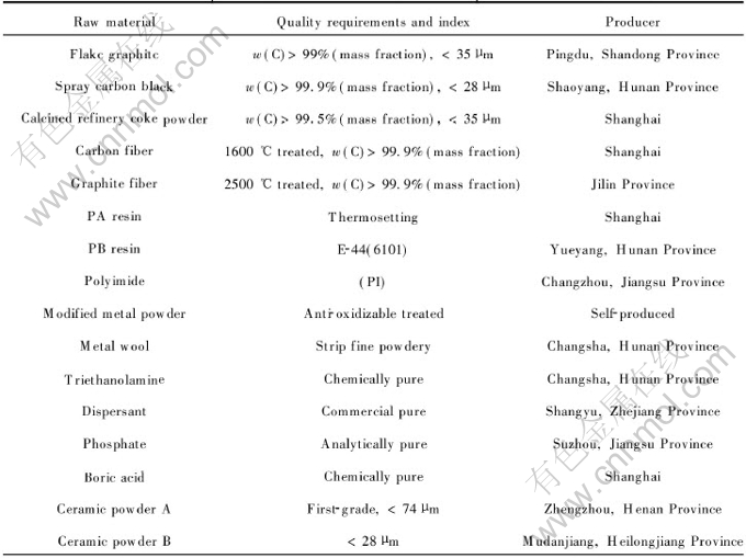
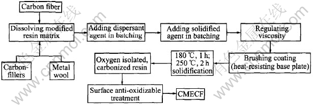
Fig.1 Preparation process flowsheet of CMECF
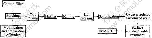
Fig.2 Preparation process flowsheet of HPMETCF
2.3 Performance testing of composite electroheat carbon film
The microstructure and particle dispersion status of the composite electroheat carbon film were observed by JSM-5610LV SEM, the surface electroheat temperature was measured by 6801A hygronom, the performance variation during electroheat process was tested by STA449C (Germany) DSC/TG thermal analyzer , while the volume resistivity and adhesion were tested according to GB1994.2��88 and GB/T9286��1998, respectively.
3 ANALYSIS AND DISCUSSION
3.1 Temperature dependence of volume resistivity of electroheat carbon film
The electrical conductivity of the electroheat carbon film is not only highly related to the heat treatment temperature and the constant temperature time during carbonization, but also affected by the electroheat temperature of the carbon film. The volume resistivities of the electroheat carbon film at different electroheat temperatures are shown in Fig.3.
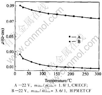
Fig.3 Volume resistivities(��) of electroheat carbon film at different electroheat temperatures
As can be seen in Fig.3 that within the range of this experiment, the volume resistivities of both CMECF and HPMETCF decrease as the electroheat temperature increases, but with different speeds. The volume resistivity of CMECF below a surface electroheat temperature of 120�� has a higher decreasing speed which gradually decreases as the electroheat temperature increases. The volume resistivity of HPMETCF below a surface electroheat temperature of 90�� has a higher decreasing speed which gradually decreases as electroheat temperature increases till 210-300�� at which it finally slows down. The fact that the volume resistivities of both CMECF and HPMETCF decrease as the electroheat temperature increases. This indicates that both of them have negative temperature-coefficient characteristic called NTC characteristic[11, 12]. For different electroheat carbon films at the same electroheat temperature, there is a rather large difference in the volume resistivity, owing to the differences of conductive filler content of the material, film thickness and amorphous carbon structure of resin binder formed during the solidification, polycondensation and carbonization. The characteristic that the volume resistivity of electroheat carbon film decreases as electroheat temperature increases, is advantageous to the quick warming-up process.
3.2 Microstructure analysis of electroheat carbon film by SEM
The effect of composition, component, microstructure and conducting particle of different materials on the electrical conductivity and electroheat property was studied by observations on both CMECF and HPMETCF by SEM. The SEM morphologies of CMECF and HPMETCF are shown in Fig.4 and Fig.5 respectively.
As shown in Figs.4(a) and (b), the surface structure of CMECF is similar and compact, and has good isotropy which can be seen from the aperture size, conducting particle dispersion and contact status. Figs.4(c) and (d) show the SEM morphologies of the carbon fiber added CMECF. The conducting bridging structure which is formed by carbon fiber and carbon powder and at the same time enriching the carbon conducting network configuration, can easily be seen.
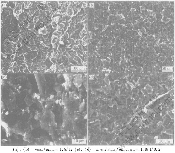
Fig.4 SEM morphologies of CMECF

Fig.5 SEM morphologies of HPMETCF
The surface microstructure of HPMETCF is shown in Figs.5(a) and (b) while the cross-section microstructure shown in Figs.5(c) and (d). As can be seen in the SEM morphologies of HPMETCF, the surface microstructure appears to be structurally integrated and compact with small voids between the conducting fillers and good contact between conducting particles. The cross-section SEM morphologies show that the conducting materials of HPMETCF are also compactly arranged with small voids between the conducting fillers. It is due to the flaking treatment which makes the fillers homogeneously dispersed over the matrix material and their binding power reinforced, so as to yield a smaller volume resistivity at room temperature and better electroheat property of HPMETCF.
3.3 Electroheat property analysis of electroheat carbon film
The electrical conductivity of electroheat carbon film is the inherent property of carbon materials. The electroheat principle is the Joule-Lenz��s law Q=I2Rt, where Q is the quantity of heat(Joule), I is the current, R is the resistance and t is the time. That is to say, the principle of heating-up object by resistance heating during electrification to make object warm-up, give off and transfer heat. The electric-thermal conversion mode of the electroheat carbon film is resistance heating. The electroheat carbon film and HPMETCF were prepared following their own preparation process flow, and the dimensions were 100mm��25mm by 0.08mm in thickness and 60mm��30mm by 0.35mm in thickness, respectively. The surface electroheat temperatures at various low voltages was tested (experiment condition: at room temperature of 19��2��,the insulated proof box volume of 200mm��200mm��200mm) , and the results are illustrated in Fig.6.
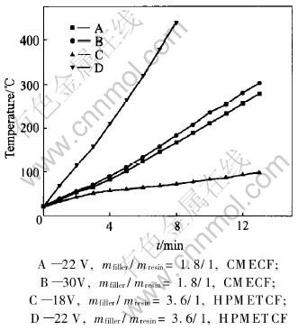
Fig.6 Heating curves of composite electroheat carbon film at various low voltages
Comparing the heating-up curves in Fig.6, it can be found that, the surface electroheat temperatures of the CMECF and HPMETCF under the same conditions are correspondingly lower at lower external voltages, whereas higher at higher external voltages. For instance, CMECF, at a voltage of 30V for 5min, reaches a surface electroheat temperature of 112�� and 236�� for 10min, at a voltage of 22V for 5min, reaches 103�� and 212�� for 10min, the hot pressing electroheat thick carbon film, at a voltage of 22V for 5min, reaches a surface electroheat temperature of 265�� and 440�� for 8min, at a voltage of 18V for 5min, reaches 60�� and 82�� for 10min. As can be seen in Fig.6, under the same conditions and a voltage of 22V, the surface electroheat temperature of HPMETCF whose volume resistivity is 0.026����cm at room temperature is higher than that of CMECF whose volume resistivity is 0.091����cm at room temperature. Both CMECF and HPMETCF show an apparent electroheat property in a short time, and have a large heat transfer area through which the quantity of heat can swiftly transfer to the warmed-up object.
3.4 Therm-alanalysis of electroheat carbon film
After electrified for a period of time, physico-chemical reactions would take place at a definite temperature within CMECF and the hot pressing electroheat thick carbon film, accompanied with the calorific effect and variations of some physical parameters. In order to test the heat-resisting property of CMECF and the hot pressing electroheat thick carbon film, DSC/TG thermal analyzer was used to study the changes of CMECF and HPMETCF during the heating-up process. The therm-alanalysis results of CMECF without anti-oxidizable treatment and HPMETCF in hot air are shown in Fig.7 and Fig.8, respectively.
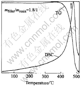
Fig.7 DSC/TG patterns of CMECF at 500��
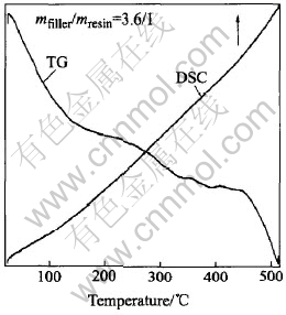
Fig.8 DSC/TG patterns of HPMETCF at 500��
As can be seen in Fig.7, from room temperature to 400��, the mass of CMECF is basically the same, and there is no peak in the DSC curve, above 450��, a severe mass loss takes place, CMECF begins to burn and a severe absorption peak appears close to the temperature of 450�� in the DSC curve. All of these indicate that CMECF is heat stabilized in hot air below 400��, and begins to lose mass near 450��. As can be seen in Fig.8 that, from room temperature to 450��, there is only 1.0%(mass fraction) of mass loss of the hot pressing electroheat thick carbon film, above 450��, an obvious mass loss takes place but there is no absorption peak formed in the DSC curve from room temperature up to 500��.
The results indicate that, in the oxidizing environment, mass loss caused by oxidization basically doesn��t take place in CMECF below 400�� while in HPMETCF below 450��, it takes place near 450��. Thus, the use value of electroheating at high temperatures can only be achieved when the electroheat carbon film anti-oxidizable treated or working in the definite reducing and inert atmosphere.
3.5 Effect of surface anti-oxidizable treatment on electroheat carbon film
Carbon materials have many excellent properties such as excellent electroheat property and chemical stability, unique high-temperature stability as well as mechanical intensity[10, 13-15]. Reactions in which amorphous carbon is formed, have taken place within the resin matrix of the carbonized CMECF and HPMETCF during solidification, polycondensation and carbonization[16-18], and a close-packed carbon network configuration has been formed for the amorphous carbon would wrap around the graphite particles during the reactions. Thus, CMECF and HPMETCF have similar properties, such as excellent electroheat property and chemical stability, to those of the carbon materials. However, at the temperature near 450�� and in an oxidizing environment, it can be easily oxidized, which may cause damages to the coating as well as to its structure, and finally a degradation of the combination properties. In view of the oxidation loss taking place not only on the surface of the carbon film but also internally, we consider using ceramic powder A, ceramic powder B, a small quantity of phosphate and soluble glass to prepare the anti-oxidizable coating used in the anti-oxidizable treatment of CMECF. The process was as below: first, the electroheat carbon film was infiltrated with boric compound solution, in a second step, the anti-oxidizable coating was brushed on the dry electroheat carbon film, which was then, in a third step, treated at a high temperature. The performance parameters of CMECF with and without anti-oxidizable treatment are shown in Table 2.
Table 2 Performance parameter of CMECF
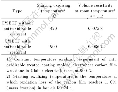
As can be seen in Table 2, CMECF without anti-oxidizable treatment, whose starting oxidizing temperature in air is only about 450��, can��t reach a high temperature, owing to the short circuit that may possibly occur because of the partial oxidization caused by the cracks on the surface of the carbon film. While the anti-oxidizable treated CMECF with good anti-oxidizability keeps a proper electro-physical parameter in hot air at 900�� for 24h.
3.6 Effect of different resins on performances of electroheat carbon film prepared by carbonization
The resin matrix is a significant component of the coating ingots, which highly relates to the fundamental properties, such as adhesion and heat resistance of the electroheat coating. In addition, it forms amorphous carbon which may greatly affect the electroheat property of the electroheat carbon film after thermolysis and carbonization, during which a close-packed carbon network configuration joined by carbon powder and carbon fiber is formed. The performances of the electroheat carbon film coatings carbonized from three different resin coatings are shown in Table 3.
Table 3 Performance comparison of electroheat carbon film after thermolysis and carbonization
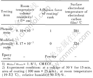
Phenolic resin which has a high carbon residue content of 76.6%(mass fraction)[10] theoretically after carbonization, is an excellent matrix for preparing resinous composites. And the modified phenolic resin has a higher carbon content and carbon residue content. But epoxide resin is easily smashed during carbonization owing to its structure. Therefore, under the same conditions, the volume resistivity (at room temperature) of the eletroheat carbon film prepared by carbonizing the modified phenolic resin coating, is lower than that prepared by carbonizing the pure phenolic resin,whereas the surface electroheat temperature of the electroheat carbon film prepared by carbonizing the modified phenolic resin coating is higher than that prepared by carbonizing the pure phenolic resin.
REFERENCES
[1]Januszkiewicz K T. Numerical model of the heating-up system with heating rods [J]. Advances in Engineering Software, 1999, 30 (2): 141-145.
[2]Flandin L, Bidan G, Brechet Y, et al. New nanocomposite materials made of an insulating matrix conducting fillers process and properties [J]. Polymer Composites, 2000, 21(2): 165-174.
[3]TU Chuan-jun, XIA Jin-tong, ZHANG Wen-hao. Current study and development of carbon-filled conductive coating [J]. Carbon Techniques, 2004, 23(3): 31-36.
[4]Ogawao Y H,Koboy A S. Influence of grinding on the graphitaiztion and densification of coke powder [J].J Mater Sci,1981, 16(8): 1281-2187.
[5]DENG An-ping, DU Heng-qing, CHEN Shi-shan, et al.Study on conductive paints [J]. Journal of Ocean University of Qingdao,1999, 29(S1): 226-228.
[6]Kulkarni V G. Tuned conductive coatings from polyaniline [J]. Synthetic Metals, 1995, 71: 2129-2131.
[7]LI Bing-huan, CAO Wen-hua, JIA Jing-xian. Preparation of new electrothermal film [J]. China Ceramics, 2001, 37(4): 29-30.
[8]Yang L L, McGhie A R. Ionic conductivity in complexes of poly(ethylene oxide) and MgCl2 [J]. J Electrohem Soc, 1986, 133: 1380.
[9]TU Chuan-jun, XIA Jin-tong, LU Xue-feng. Study on the conductive and heating coating with compound carbon-fillers [J]. J Cent South Univ (Science and Technology),2005, 36(1): 25-29.
[10]QING Zhan-fang. Carbon Technics [M]. Beijing: Metallurgical Industry Press, 2001. 176-177.
[11]LI You-fen, SUN Gen-sheng, WU Shi-min, et al. Measurement and study of resistivity of conductive ceramics based on La2O3 [J]. The Chinese Journal of Nonferrous Metals, 1997, 7(1): 159-161.
[12]LI Cheng-yi. Improvement of film layer TCR of carbon resistors having high resistivity [J]. Electron Compon Mater, 1995, 14(5): 28-30.
[13]ZHAO Geng-xiang. Carbon film [J]. New carbon Materials, 2003, 18(3): 237-238.
[14]Okpalugo T I T, Maguire P D, Ogwu A A, et al. The effect of silicon doping and thermal annealing on the electrical and structural properties of hydrogenated amorphous carbon thin films [J]. Diamond and Related Materials, 2004, 13: 1549-1552.
[15]Lukaszewicz J P. Controlling of surface and humidity detecting properties of carbon films-selection of a precursor for carbonization [J]. Thin Solid Films, 2001, 391(2): 270-274.
[16]Zhong D H, Sano H, Kobayashi K, et al. A study of film thickness dependence of the graphitizability of PMDA-ODA polyimide-derived carbon film [J]. Carbon, 2000, 38(15): 2161-2165.
[17]Tsou H T, Kowbel W. A hybrid PACVD SiC/CVD Si3N4/SiC multiplayer coating for oxidation protection of composites [J]. Carbon,1995, 33(9): 1279-1288.
[18]Koning R I, Oostergetel G T. Preparation of flat carbon support films [J]. Ultramicroscopy, 2003, 94(3): 183-191.
Foundation item: Project(59972009) supported by the National Natural Science Foundation of China
Received date: 2005-03-18; Accepted date:2005-07-08
Correspondence: XIA Jin-tong, Professor, PhD; Tel: +86-13975105152; E-mail: xjt8821059@163.com
