

Effect of frictions on cross section quality of thin-walled tube NC bending
YANG He(�� ��), GU Rui-jie(�����), ZHAN Mei(ղ ÷), LI Heng(�� ��)
College of Materials Science and Engineering, Northwest Polytechnic University, Xi��an 710072, China
Received 21 September 2005; accepted 16 March 2006
Abstract:
The effect of frictions between dies and tube on the cross section quality of thin-walled tube numerical controlled(NC) bending was studied by numerical simulation method, combined with theoretical analysis and experiment. The results show that the frictions between mandrel, wiper, pressure die, bending die and tube have a significant and complicate effect on the section quality of thin-walled tube NC bending. To improve the section quality, frictions between mandrel, wiper and tube should be decreased, but the frictions between the pressure die, bending die and tube increase. The effect on the section distortion is more significant from mandrel, wiper, pressure die to bending die and the effect on the wall thinning more significant from mandrel, pressure die, wiper, to bending die. The effects of frictions between all dies and tube on wall thinning are smaller than their effects on section distortion. Mandrel and wiper should be lubricated well and drawing oil is used to lubricate them in actual production. The frictions between pressure die, bending die and tube should be increased and the dry friction is used between pressure die, bending die and tube in actual production.
Key words:
thin-walled tube; tube NC bending; friction; cross section quality;
1 IntroductionThin-walled tube bending parts have been increasingly used in many industry fields such as aviation, aerospace and automobile for their easy satisfaction in light weight, high strength and low consuming. The numerical controlled(NC) rotary-draw tube bending technology not only enables the forming process high technicalization, but also can satisfy the requirements of high precision, high efficiency, digitalization and intellectualization. So in aviation, aerospace and automobile industries, the cold NC tube bending process has been developed as one of the most important tube bending technologies[1].
In the forming process, cracking and wrinkling can be avoided, but the cross section distortion and the wall thinning are inevitable. Cracking and wrinkling should be avoided firstly, then that the cross section distortion and the wall thinning should be decreased as far as possible in the forming process. The frictions between several dies and tube have a significant effect on the section quality of thin-walled tube NC bending. And the effect is very complicate because there are so many interfaces. However, up till now, much research put emphasis on tube bending[2-18], but the reported literature about the effect of friction on the section quality has not been reported. The effect of the frictions between dies and tube on the cross section quality of thin-walled tube NC bending is studied by numerical simulation method, combined with theoretical analysis and experiment. The achievements of this study are useful to determining reasonable friction conditions in the process, and the method of numerical simulation can be used to study other parameters�� effect on the forming quality of NC tube bending.
2 Principle of thin-walled tube NC bending and its cross section quality
Fig.1 shows the sketch of tube NC bending process. The bending die is fixed on the major axes of the machine tool and revolves together with the major axes. The leading end of tube is pressed tightly on the bending die by the clamp die. The pressure die is set on outer part, the wiper die set on inner part of tube bending and the mandrel set in the tube on the tangency point between the tube and the bending die. When the bending die revolves, the tube is bent and formed gradually into the desired bending shape under the cooperation of the clamp die, the pressure die and the bending die.
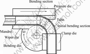
Fig.1 Sketch of tube NC bending
Fig.2 shows the state of stress and strain during NC tube bending process. In the process, the outer material of bending tube will be elongated under tensile stress in the tangential direction, which leads to the wall thinning, and the inner material of bending tube be shortened under compressive stress in the tangential direction, which leads to the wall thickening. Meanwhile both the composite force of tangential stress of inner part and that of outer part point to the center of the cross section of tube, which causes the cross section distorting (Fig.3).
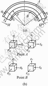
Fig.2 State of stress and strain during tube bending
The change ratio of vertical axes (��D) may be used to describe the degree of the cross section distortion of thin-wall tube NC bending and the thinning ratio of outermost wall of the section (��t) is used to describe the degree of the wall thinning of thin-wall tube NC bending [18].
![]() (1)
(1)
where D is the length of cross section��s vertical axes before bending, D�� is the length of cross section��s vertical axes after bending.
![]() (2)
(2)
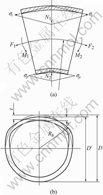
Fig.3 Cross sections distorting and wall thinning of tube bending
where t is the wall thickness on the outermost part before bending, t�� is the wall thickness on the outermost part after bending.
3 Finite element model of thin-walled tube NC bending
According to the principle of NC tube bending (Fig.1), the 3D finite element model of thin-walled tube NC bending (shown in Fig.4) based on the DYNAFORM platform was established. The establishing and verifying process of the model was similar to that in Ref.[18].
3.1 Finite element model of thin-walled tube NC bending and its key technologies
3.1.1 Determination of loading way
Tube NC bending is loaded through displacement. The bending die revolves around its own center and the pressure die translates along X direction (Fig.4) in DY-
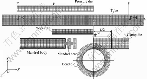
Fig.4 Finite element model of thin-walled tube NC bending
NAFORM. The upper clamp die and the down clamp die are simplified as one clamp die and its movement is divided into three movements in different directions including the translation along the X direction, the translation along the Y direction and the revolution around the Z axes across the gravity center of the clamp die.
3.1.2 Selection of element
Because not only the precision but also the efficiency of computing are high to simulate thin-walled parts forming with the shell element, so shell element is used to dispose the tube when thin-walled tube NC bending is simulated.
3.1.3 Selection of material model
Because tube NC bending is a kind of cold bending technology and the material will get hardened during bending, the model of index hardening material is chosen to simulate the forming of thin-walled tube NC bending. The relation of stress and strain can be expressed as
![]() (3)
(3)
where K is stiffness factor, n is hardening index.
3.1.4 Determination of finite element computing algorithm
Dynamic explicit algorithm is based on the central difference algorithm, which causes nonlinear equations explicit and the iteration avoided. Not only the precision but also the efficiency of computing are high with the dynamic explicit algorithm, so set of equations are resolved with the dynamic explicit algorithm in the simulation.
3.1.5 Treatment of contact boundary
Penalty function method is to introduce contact condition into set of equations as penalty, which doesn��t increases system��s degrees of freedom, so the computing efficiency is high. The penalty function method suits to explicit computing, so it is used to deal with the contact constraint in the research.
3.1.6 Determination of friction model
The friction has an important influence on the process of tube NC bending, so it is necessary to introduce a proper friction model into the finite element simulation. The process of tube NC bending is under- gone under cold condition, so cohere should be ignored. Here, Coulomb friction model is used to compute the friction in which friction is proportional to normal pressure. The mathematical expression of Coulomb friction model is
![]() (4)
(4)
where �� is equivalent shear stress, �� is friction coefficient, ��n is equivalent normal stress, and ��min is ultimate shear stress.
3.2 Experimental verification of finite element model
The equipment of experiment is W27YPC��63 full- automatic tube bender controlled with hydraulic pressure by programmable logic controller(PLC). Parameters of dies are as follows: the length of clamp die is 116 mm, the length of pressure die is 260 mm, the length of wiper is 140 mm, the diameter of mandrel is 35.7 mm and its length is 150 mm. The material used in experiment is LF2M aluminum alloy tube, whose parameters are as follows: stiffness coefficient is 237 MPa, hardening index 0.263 4 and elastic modulus 55.67 GPa. Para- meters of the bending tube are as follows: the diameter of tube is 38 mm, the wall thickness 1mm and the radius of bending 57 mm. In the experiment, bending angle is set as 90?, angular speed as 30(?)/s and the mandrel includes one head. All dies except the clamp die are well lubricated with hydraulic oil (friction coefficient is 0.1). The clearance and pressure between the clamp die and the tube are adjusted to ensure that the tube is clamped tightly but has no clamp mark, and the clearance between the pressure die and the tube is adjusted to 0.5 mm.
Fig.5 compares the result of simulation with that of experiment, where abscissa is the angle between certain section and the initial bending section and ordinate is the change ratio of vertical axes length. From Fig.5, it is discovered that the result of simulation and that of experiment agree with each other. The error ratio doesn��t exceed 10% at sections whose distortion is large and doesn��t exceed 20% at sections whose distortion is small. The finite element simulation model is verified to be credible.

Fig.5 Comparison of vertical axes length change ratio of simulation with that of experiment
4 Results and discussion
Parameters of dies, tube material, tube geometry and process in simulation are the same as those in experiment. According to Ref.[18], the mandrel can take two heads or three heads. Friction coefficient between the mandrel, the wiper, the pressure die, the bending die and the tube can be set as 0.05, 0.1, 0.2, 0.3, 0.4 or 0.5 in the simulation. Cracking and wrinkling are not found in the simulation, which provides the basis for the further research on the cross section distortion and wall thinning.
According to Ref.[18], it can be gained that when the mandrel takes two heads, the section, located at the angle of 20? with the initial bending section, distorts most seriously, and when the mandrel takes three heads, the initial bending section distorts most seriously. The maximum of outermost wall thinning lies in a large range of angle between the middle section and the initial bending section of bending tube. The major factors used to evaluate section quality of bending tube are the maximal section distortion and the maximal wall thinning, so only these sections between the initial bending section and the section located at the angle of 50? with the initial bending section will be considered in the following research.
4.1 Effect of friction between mandrel and tube on cross section quality during thin-walled tube NC bending
The friction between mandrel and tube has a large effect on the section quality of thin-walled tube NC bending. When the friction coefficient is larger than 0.2 (?��0.2), although the friction between clamp die and tube is very large, there is still slip between them, which causes section quality out of control. In order to express clearly the effect of the friction between mandrel and tube on the section quality, another friction coefficient (?=0.15) is used to simulate the process of thin-walled tube NC bending. So there are three friction coefficient values (0.05, 0.1 and 0.15) shown in Figs.6 and 7.
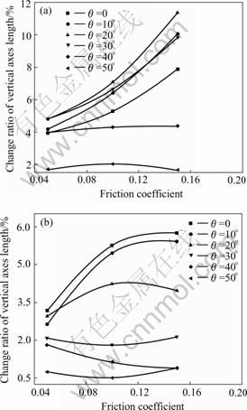
Fig.6 Effect of friction between mandrel and tube on change ratio of vertical axes length: (a) n=2; (b) n=3
The effect of the friction between mandrel and tube on the vertical axes length change ratio of different cross sections is shown in Fig.6. When the mandrel takes two heads (n=2), the section, located at the angle of 20? with the initial bending section, distorts most seriously, the maximum of section distortion increases from 4.80% to 11.38% with the friction coefficient increasing from 0.05 to 0.15, and the amplitude reaches 137.08%. When the mandrel takes three heads (n=3), the initial bending section distorts most seriously, the maximum of section distortion increases from 3.17% to 6.25% with the friction coefficient increasing from 0.05 to 0.15, and the amplitude of increasing reaches 97.16%. It is because that the increase of friction between mandrel and tubeincreases the resistance of tube bending, which causes tangential stress increasing.
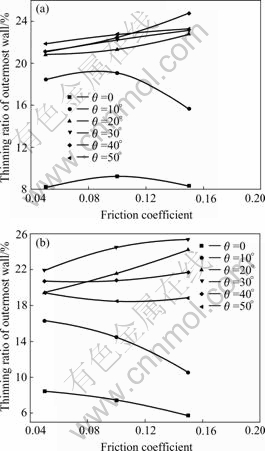
Fig.7 Effect of friction between mandrel and tube on thinning ratio of outermost wall: (a) n=2; (b) n=3
The effect of the friction between mandrel and tube on the outermost wall thinning of different cross sections is shown in Fig.7. When the mandrel takes two heads (n=2) and the friction coefficient between the wiper and tube is smaller than 0.1 (�̡�0.1), the section, located at the angle of 50? with the initial bending section, thins down most seriously; when the mandrel takes two heads (n=2) and the friction coefficient between wiper and tube is 0.15 (��=0.15), the section, located at the angle of 40? with the initial bending section, thins down most seriously. The maximum of section wall thinning increases from 21.86% to 24.79% with the friction coefficient increasing from 0.05 to 0.15, and the amplitude reaches 13.40%. When the mandrel takes three heads (n=3), the section, located at the angle of 30? with the initial bending section, thins down most seriously. The maximum of section distortion increases from 21.96% to 25.36% with the increasing of friction from 0.05 to 0.15, and the amplitude of increasing reaches 15.48%. It is because that the increase of friction between mandrel and tube increases the resistance of tube bending, which causes tangential stress and normal strain increasing.
4.2 Effect of friction between wiper and tube on cross section quality during thin-walled tube NC bending
The effect of the friction between wiper and tube on the vertical axes length change ratio of different cross sections is shown in Fig.8. When the mandrel takes two heads (n=2), the section, located at the angle of 20? with the initial bending section, distorts most seriously. The maximum of section distortion increases from 6.89% to 11.19% with the friction coefficient increasing from 0.05 to 0.5, and the amplitude reaches 62.41%. When the mandrel takes three heads (n=3) and the friction coefficient between wiper and tube is smaller than 0.2 (�̡�0.2), the initial bending section distorts most seriously;
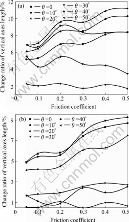
Fig.8 Effect of friction between wiper and tube on change ratio of vertical axes length: (a) n=2; (b) n=3
when the mandrel takes three heads (n=3) and the friction coefficient between wiper and tube is bigger than 0.3 (�̡�0.3), the section, located at the angle of 10? with the initial bending section, distorts most seriously. The maximum of section distortion increases from 4.92% to 9.26% with the coefficient friction increasing from 0.05 to 0.5, and the amplitude of increasing reaches 88.21%. It is because that the increase of friction between wiper and tube increases the resistance of tube bending, which causes tangential stress increasing.
The effect of the friction between wiper and tube on the outermost wall thinning of different cross sections is shown in Fig.9. When the mandrel takes two heads (n=2) and the friction coefficient between wiper and tube is smaller than 0.1 (�̡�0.1), the section, located at the angle of 50? with the initial bending section, thins down most seriously; when the mandrel takes two heads (n=2) and the friction coefficient between wiper and tube is bigger than 0.2 and smaller than 0.4 (0.2�ܦ̡�0.4), the section, located at the angle of 40? with the initial bending section, thins down most seriously; when the mandrel takes two heads (n=2) and the friction coefficient between wiper and tube is 0.5 (��=0.5), the section, located at the angle of 30? with the initial bending section, thins down most seriously. The maxi-
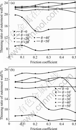
Fig.9 Effect of friction between wiper and tube on thinning ratio of outermost wall: (a) n=2; (b) n=3
mum of section wall thinning increases from 22.47% to 24.28% with friction coefficient increasing from 0.05 to 0.5, and the amplitude reaches 8.06%. When the mandrel takes three heads (n=3), the section, located at the angle of 30? with the initial bending section, thins down most seriously. The maximum of section distortion increases from 23.55% to 26.40% with the friction coefficient increasing from 0.05 to 0.5, and the amplitude reaches 12.10%. It is because that the increase of friction between wiper and tube increases the resistance of tube bending, which causes tangential stress and normal strain increasing.
4.3 Effect of friction between pressure die and tube on cross section quality during thin-walled tube NC bending
The effect of the friction between pressure die and tube on the vertical axes length change ratio of different cross sections is shown in Fig.10. When the mandrel takes two heads (n=2) and the friction coefficient between pressure die and tube is smaller than 0.2 (�̡�0.2), the section, located at the angle of 20? with the initial bending section, distorts most seriously. When the mandrel takes two heads (n=2) and the friction coefficient between pressure die and tube is bigger than
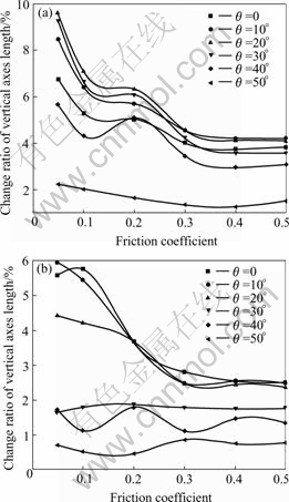
Fig.10 Effect of friction between pressure die and tube on change ratio of vertical axes length: (a) n=2; (b) n=3
0.3 (�̡�0.3), the section, located at the angle of 10? with the initial bending section, distorts most seriously. The maximum of section distortion decreases from 9.62% to 4.21% with the friction coefficient increasing from 0.05 to 0.5, and the amplitude reaching 56.24%. When the mandrel takes three heads (n=3) and the friction coefficient between pressure die and tube is 0.05 (��=0.05), the section, located at the angle of 10? with the initial bending section, distorts most seriously; when the mandrel takes three heads (n=3) and the friction coefficient between pressure die and tube is bigger than 0.1 (�̡�0.1), the initial bending section distorts most seriously. The maximum of section distortion decreases from 5.95% to 2.50% with the friction coefficient from 0.05 to 0.5, and the amplitude reaches 63.95%. It is because that the increase of friction between pressure die and tube decreases the resistance of tube bending, which causes tangential stress decreasing.
The effect of the friction between pressure die and tube on the outermost wall thinning of different cross sections is shown in Fig.11. When the mandrel takes two heads (n=2) and the friction coefficient between wiper and tube is smaller than 0.1 (�̡�0.1), the section, located at the angle of 40? with the initial bending section, thins down most seriously; when the mandrel takes two heads
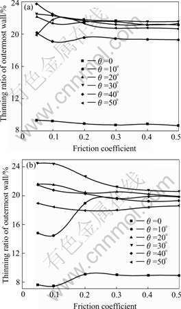
Fig.11 Effect of friction between pressure die and tube on thinning ratio of outermost wall: (a) n=2; (b) n=3
(n=2) and the friction coefficient between wiper and tube is bigger than 0.2 (�̡�0.2), the section, located at the angle of 30? with the initial bending section, thins down most seriously. The maximum of section wall thinning decreases from 23.74% to 21.54% with the friction coefficient increasing from 0.05 to 0.5, and the amplitude reaches 9.27%. When the mandrel takes three heads (n=3), the section, located at the angle of 30? with the initial bending section, thins down most seriously, the maximum of section distortion increases from 24.49% to 20.55% with the friction coefficient increasing from 0.05 to 0.5, and the amplitude reaches 16.09%. It is because that the increase of friction between pressure die and tube decreases the resistance of tube bending, which causes tangential stress and normal strain decreasing.
4.4 Effect of friction between bending die and tube on cross section quality during thin-walled tube NC bending
The effect of the friction between bending die and tube on the vertical axes length change ratio of different cross sections is shown in Fig.12. When the mandrel takes two heads (n=2) and the friction coefficient between bending die and tube is smaller than 0.3 (?��0.3), the section, located at the angle of 20? with the
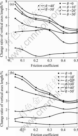
Fig.12 Effect of friction between bending die and tube on change ratio of vertical axes length: (a) n=2; (b) n=3
initial bending section, distorts most seriously. When the mandrel takes two heads (n=2) and the friction coefficient between pressure die and tube is larger than 0.4 (�̡�0.4), the section, located at the angle of 10? with the initial bending section, distorts most seriously. The maximum of section distortion decreases from 7.96% to 4.55% with the friction coefficient increasing from 0.05 to 0.5, and the amplitude reaches 42.84%. When the mandrel takes three heads (n=3) and the friction coefficient between pressure die and tube is smaller than 0.3 (�̡�0.3), the initial bending section distorts most seriously; when the mandrel takes three heads (n=3) and the friction coefficient between bending die and tube is bigger than (�̡�0.4), the section, located at the angle of 10? with the initial bending section, distorts most seriously. The maximum of section distortion decreases from 6.04% to 3.09% with the friction coefficient increasing from 0.05 to 0.5, and the amplitude reaches 48.84%. It is because that the increase of friction between bending die and tube decreases the resistance of tube bending, which causes tangential stress decreasing.
The effect of the friction between bending die and tube on the outermost wall thinning of different cross sections is shown in Fig.13. When the mandrel takes two heads (n=2) and the friction coefficient between bending
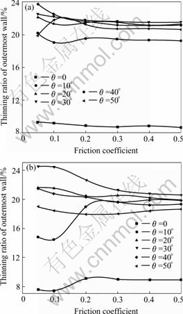
Fig.13 Effect of friction between bending die and tube on thinning ratio of outermost wall: (a) n=2; (b) n=3
die and tube is smaller than 0.1 (�̡�0.1), the section, located at the angle of 40? with the initial bending section, thins down most seriously. When the mandrel takes two heads (n=2) and the friction coefficient between wiper and tube is bigger than 0.2 (�̡�0.2), the section, located at the angle of 30? with the initial bending section, thins down most seriously. The maximum of section wall thinning increases from 23.20% to 22.04% with the friction coefficient increasing from 0.05 to 0.5, and the amplitude reaches 5.00%. When the mandrel takes three heads (n=3), the section, located at the angle of 30? with the initial bending section, thins down most seriously, the maximum of section distortion decreases from 24.46% to 21.80% with the friction coefficient increasing from 0.05 to 0.5, and the amplitude reaches 10.87%. It is because that the increase of friction between bending die and tube decreases the resistance of tube bending, which causes tangential stress and normal strain decreasing.
4.5 Selection of reasonable friction condition during thin-walled tube NC bending
The frictions between mandrel, wiper, pressure die, bending die and tube have a significant and complicate effect on the section quality of thin-walled tube NC bending. Decreasing the frictions between mandrel, wiper and tube is helpful to improve the section quality, but increasing the frictions between the pressure die, bending die and tube is helpful to improve the section quality. In these four frictions, the effect on section distortion is more significant from mandrel, wiper, pressure die to bending die and the effect on wall thinning are more significant from mandrel, pressure die, wiper, to bending die. The effect of the friction between all dies and tube on the wall thinning is smaller than its effect on the section distortion because its effect on stress is bigger than its effect on strain and the section distortion mainly depends on the tangential stress and wall thinning mainly depend on normal strain.
According to the different usage of the bending tube, the requirements on the section quality are different. In production, except that the cross section distortion and the wall thinning must satisfy the requirements, surface quality should be improving and the abrasion of dies decreased as far as possible. According to the above results and discussion: mandrel and wiper should be lubricated well to ensure the frictions between them and tube small enough. In actual product, drawing oil may be used to lubricate the mandrel and wiper. In theory, the frictions between the pressure die and bending die and tube should be increased. But if they are large, pressure die and bending die may scuff the tube and be abraded seriously, so dry friction is used among the pressure die, bending die and tube in actual product. The friction condition has been verified to be a good friction state with the experiment.
5 Conclusions
1) The frictions between mandrel, wiper, pressure die, bending die and tube have a significant and complicate effect on the section quality of thin-walled tube NC bending. Decreasing the frictions between mandrel, wiper and tube, but increasing the frictions between pressure die, bending die and tube is helpful to improving the section quality.
2) The effect on the section distortion is more significant from the mandrel, wiper, pressure die to the bending die and the effect on the wall thinning is more significant from the mandrel, pressure die, wiper, to the bending die.
3) The effects of the frictions between all dies and tube on wall thinning is smaller than their effects on section distortion.
4) Mandrel and wiper should be lubricated well to ensure the frictions between them and tube are small enough. In actual product, drawing oil may be used to lubricate them. In theory, the frictions among the pressure die, bending die and tube should be increased. But if they are large, pressure die and bending die may scuff the tube and be abraded seriously, so dry friction is used among the pressure die, bending die and tube in actual product.
References[1] YANG He, LIN Yan, SUN Zhi-chao. Review of advanced plastic processing technology and tube forming facing 21st century [A]. Symposium of 2nd China Science Association Annual Conference [C]. Beijing: Science and Technology Press, 2000. 745-746. (in Chinese)
[2] YANG H, ZHAN M, LIU Y L. Some advanced plastic processing technologies and their numerical simulation [J]. Journal of Materials Processing Technology, 2004, 151: 63-69.
[3] YANG He, LIN Yan. Wrinkling analysis for forming limit of tube bending processes [J]. Journal of Materials Processing Technology, 2004, 152: 363-369.
[4] ZHAN M, YANG H, JIANG Z Q. A study on a 3D FE simulation method of the NC bending process of thin-walled tube [J]. Journal of Materials Processing Technology, 2002, 129: 273-276.
[5] LI H, YANG H, ZHAN M, GUO L G, GU R J. Wrinkling limit based on FEM virtual experiment during NC bending process of thin-walled tube [J]. Materials Science Forum, 2004, 471-472: 498-502.
[6] AL-QURESHI H A. Elastic-plastic analysis of tube bending [J]. Journal of Machine Tools & Manufacture, 1999, 39: 87-104.
[7] LI H Z, FAGERSON R. A method of adaptive control of rotary-draw thin-walled tube bending with springback compensation [J]. Transaction NAMRI/SME, 1994, XXII: 25-28.
[8] KIM A S. The deformation of shape [J]. Journal of Engineering Materials and Technology, 2000, 121: 320-326.
[9] TANG N C. Plastic-deformation analysis in tube bending [J]. International Journal of Pressure Vessels and Piping, 2000, 77: 751-759.
[10] KRISTOFFER TRANA. Finite element simulation of the tube hydroforming process��bending, preforming and hydroforming [J]. Journal of Materials Processing Technology, 2002, 127: 401-408.
[11] JIN Z, LUO S, DANIEL FANG X. KBS-aided design of tube bending processes [J]. Engineering Applications of Artificial Intelligence, 2001, 14: 599-606.
[12] KYRIAKIDES S, CORONA E, MILLER J E. Effect of yield surface evolution on bending induced cross sectional deformation of thin-walled sections [J]. International Journal of Plasticity, 2004, 20: 607-618.
[13] MILLER J E, KYRIAKIDES S. Three-dimensional effect of the bend-stretch forming of aluminum tubes [J]. International Journal of Mechanical Sciences, 2003, 45: 115-140.
[14] MILLER J E, KYRIAKIDES S, BASTARD A H. On bend-stretch forming of aluminum extruded tubes��I: experiments [J]. Interna- tional Journal of Mechanical Sciences, 2001, 43: 1283-1317.
[15] MILLER J E, KYRIAKIDES S, CORONA E. On bend-stretch forming of aluminum extruded tubes��II: analysis [J]. International Journal of Mechanical Sciences, 2001, 43: 1319-1338.
[16] ZHAN Mei, YANG He, LI Zhen. Finite element analysis of influence of mandrel on thinning ratio of wall in NC tube bending [J]. Mechanical Science and Technology, 2004, 23(6): 669-670. (in Chinese)
[17] WANG Guang-xiang, YANG He, LI Heng, ZHAN Mei, GU Rui-jie. Experimental study of the influence of processing parameters on forming quality of thin-walled NC bending tube [J]. Mechanical Science and Technology, 2005, 24(8): 995-998. (in Chinese)
[18] GU Rui-jie, YANG He, ZHAN Mei. Effect of mandrel on the cross section quality of thin-walled tube NC bending [J]. Trans Nonferrous Met Soc China, 2005, 15(6): 995-998.
(Edited by LONG Huai-zhong)
Foundation item: Project(50225518) supported by the National Science Foundation of China for Distinguished Young Scholars; Projects(50175092; 59975076) supported by the National Natural Science Foundation of China; Project supported by the Teaching and Research Award Program for Outstanding Young Teachers in Higher Education Institutions of MOE, China; Project(04H53057) supported by the Aeronautical Science Foundation of China; Project(20020699002) supported by the Specialized Research Fund for the Doctoral Program of Higher Education, China; Project(Z200518) supported by the Graduate Starting Seed Fund of Northwestern Polytechnical University, China
Corresponding author: YANG He; Tel: +86-29-88495632; E-mail: yanghe@nwpu.edu.cn
