
J. Cent. South Univ. (2017) 24: 2198-2208
DOI: https://doi.org/10.1007/s11771-017-3628-0

A comparative crashworthiness analysis of multi-cell polygonal tubes under axial and oblique loads
ZOU Xiang(����), GAO Guang-jun(�߹��), ZHANG Jie(�Ž�),
ZHOU Xi-sai(��ϸ��), CHEN Wei(����), GUAN Wei-yuan(��άԪ)
Key Laboratory of Traffic Safety on Track of Ministry of Education,
School of Traffic and Transportation Engineering, Central South University, Changsha 410075, China
 Central South University Press and Springer-Verlag GmbH Germany 2017
Abstract:
In order to investigate the energy absorption characteristics of multi-cell polygonal tubes with different cross-sectional configurations, firstly, the theoretical formulae of the mean crushing force under axial load for four multi-cell polygonal tubes were derived by combining the Super Folding Element theory with Zhang��s research results. These formulae can be used to validate the numerical model and quickly evaluate the energy absorption ability of multi-cell polygonal tubes. Furthermore, a comparative study on the energy absorption performance of eight multi-cell polygonal tubes under axial and oblique loads was conducted. The results show that all tubes have a stable mixed deformation mode under axial load. The multi-cell decagon tube has better energy-absorption ability compared with other tubes. When �� is less than 10��, all the tubes maintain a stable deformation mode, and the multi-cell decagon tube also has the biggest crushing force efficiency and specific energy absorption among these eight tubes; meanwhile compared with the results at ��=0��, the specific energy absorption of all tubes decreases by about 8%-21%, while the crushing force efficiency increases by 20%-56%. However, at large angles 20�� and 30��, all of the tubes collapse in bending modes and lose their effectiveness at energy absorption.
Key words:
1 Introduction
Thin-walled structures are widely applied as energy absorbers in automotive engineering, military engineering and other industries. In order to improve their energy absorption characteristics, extensive studies including experiments, theoretical analysis and numerical simulations, have been carried out. ALEXANDER [1] firstly developed the collapse model of circular tube and derived an approximate theoretical expression to predict the mean crushing force. Both static and dynamic studies for the circular and square tubes under axial load were done using experimental and numerical methods by ABRAMOWICZ et al [2] and WIERZBICKI et al [3]. Based on the super folding element (SFE) method proposed by CHEN et al [4], ZHANG et al [5] investigated the mean crushing force of multi-cell square tubes. And then, ZHANG also used this method to analyze the corner angle element, 3-panel angle element, and 4-panel element.
Previous studies [6�C11] have shown that dividing single-cell tubes into multi-cell tubes can improve their energy absorption characteristics effectively. The results taken from CHEN et al [4] showed that the double cell and triple cell tubes have the specific energy absorption (SEA) 15% higher than that of the single tube. ZHANG et al [12] proved that the SEA of multi-cell columns is about 50%-100% higher than that of foam-filled columns, which means the ��multi-cell�� is a better way to improve the tube��s energy absorption characteristics. NAJAFI et al [13] studied the crash behaviors of thin-walled aluminum tubes with different multi-cell, multi-corner configurations and presented a theoretical formula of mean crushing force. JUSUF et al [14] conducted a numerical and experimental study of four multi-cell tubes, including the middle ribs (MR) multi-cell tube, the corner ribs (CR) multi-cell tube, the double-walled (DW) tube and the single-walled (SW) tube. Their results showed that the MR has the highest mean crushing force, the next is the CR, the DW and the SW, respectively. QIU et al [15] studied the crashworthiness of different multi-cell hexagonal cross-sectional tubes under axial and oblique loads. He found that the multi-cell tube S4 with middle ribs connecting the outer and inner walls was the best among these seven alternative sections in energy absorption.
Because energy absorbers are usually subjected to oblique loads in practice, some works have been down on the crashworthiness of energy absorbers under oblique loads. HAN et al [16] analyzed the energy absorption characteristics of a square tube subjected to oblique loads. They found that the mean crushing force under the critical loading angle, at which a transition took place from the axial collapse mode to the bending collapse mode, drops to about 40% of the axial loads. SONG et al [17] showed a comparative analysis on the energy absorption performance of windowed and multi-cell square tubes. Their results showed that the multi-cell and windowed tubes may have worse performance than the conventional tube when the former deformed in global bending and the conventional tube deform in an axial mode. A group of multi-cell tubes with different cell numbers under both axial and oblique loads were comprehensively investigated by FANG et al [18]. GOEL [19] analyzed the energy absorption characteristics of single, double and multi-wall square and circular tubes with and without aluminum foam core. ZHANG et al [20] analyzed the crashworthiness performance and energy absorption of different polygonal section tubes and found that the mean crushing force and energy absorption will be improved when the number of polygonal section vertex increases, but there is no improvement after octagon.
Overall there appears to be relatively few researches conducted on the crashworthiness analysis of multi-cell polygonal tubes under axial and oblique loads, so we will focus on this. In this work, first the theoretical formulae of the mean crushing force under axial loads for four multi-cell polygonal tubes were developed by using the super folding element theory and ZHANG��s research results [21]. The theoretical formulae can be used to validate the numerical model and quickly evaluate the energy absorption ability of these tubes. Next, in order to analyze the crashworthiness of multi-cell polygonal tubes under axial and oblique loads, a group of multi-cell polygonal tubes were analyzed.
2 Theoretical analysis under axial load
2.1 Constituent elements of multi-cell polygonal tubes
Four multi-cell polygonal tubes, each of which contains three parts: outer tube, ribs and inner tube, are studied analytically, including the multi-cell quadrilateral tube (M4), multi-cell hexagonal tube (M6), multi-cell octagonal tube (M8), and multi-cell decagonal tube (M10), as shown in Fig. 1(a). In the derivation of theoretical formulae of the mean crushing force, each of the multi-cell polygonal tubes is divided into four parts of angle elements, which are the �� element C-1,�� element C-2, T element T-1, and T element T-2. The numbers of these elements in each multi-cell polygonal tube are listed in Table 1. It can be seen clearly in Table 1, the numbers of four kinds of elements are identical in the same tube.
Table 1 Number of each element
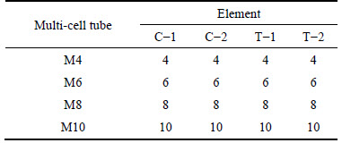
For C-1 and C-2, T-1 and T-2 in the same tube, the difference between the two are just the length of the flanges, which are half of the widths of outer tube and inner tube, respectively.
Therefore, it also can be seen that each multi-cell tube consists of two kinds of basic elements: �� element and T-shape element, as shown in Fig. 1(b). Different multi-cell polygonal tubes have different sizes of L, B and D.
2.2 Theoretical formulae of mean crushing force under axial load
During the external loading, the work done by external load is equal to the internal energy dissipation of tubes. So, the mean crushing force in the collapse of a fold is calculated by
 (1)
(1)
where H is the half wavelength of a fold; Wbending and Wmembrane are, respectively, the total bending dissipation energy and the total membrane deformation energy; �� is the coefficient of the effective crushing distance that is used to consider that the wavelength of a fold is smaller than 2H in practice. According to the research results from WIERZBICKI et al [3], the effective crush distance is about 70%-75% of the wavelength. In this work, the value of coefficient �� is firstly taken as 72%.
According to the theory of CHEN et al [4], the bending energy can be evaluated by summing up the energy dissipation at stationary hinge lines. There are 3 horizontal stationary hinge lines:
 (2)
(2)
where ��1, ��2 and ��3 are the rotation angles at the hinge line, which are ��/2, �� and ��/2, respectively; Lc is the total length of the flanges; M0 is the fully plastic moment,which can be calculated as follows:
 (3)
(3)
where ��0 is the flow stress of the structural material, and t is the wall thickness. So, the bending energy is:
 (4)
(4)
There are two main ways to calculate the value of the flow stress: one way is:
 (5)
(5)
and the other way is:
 (6)
(6)
where ��y is the yield strength; ��u is the ultimate strength; and n is the strain hardening exponent for a strain hardening material.
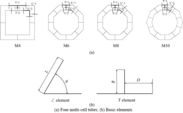
Fig. 1 Constituent elements of multi-cell polygonal tubes:
Based on the analysis of ZHANG et al [21], the membrane energy of �� element and T element can be expressed as

 (7)
(7)
 (8)
(8)
where �� is the central angle of �� element. Equation (7) just can be used in the �� element deforming in an inextensional mode. In this work, through finite element analysis below, we can know that all of the �� elements of four multi-cell polygonal tubes deform in an inextensional mode, so Eq. (7) can be used to calculate the mean crushing force.
Therefore, the total energy dissipated by membrane deformation is expressed as

 (9)
(9)
where NC-1, NC-2, NT-1 and NT-2 are the number of �� element C-1, �� element C-2, T element T-1 and T element T-2, respectively. Because NC-1, NC-2, NT-1 and NT-2 are equal to each other in one multi-cell tube, the total energy dissipated by membrane deformation also can be expressed as
 (10)
(10)
where  which are 4, 6, 8 and 10 for the M4, M6, M8 and M10, respectively.
Substituting Eqs. (7) and (8) to Eq. (10), the membrane energy is:


 (11)
(11)
where L1, L2, D1 and D2 are the length of the flanges in four kinds of angle elements, respectively; S1 and S2 are introduced as the side lengths of the outer tube and inner tube in one multi-cell tube, so it can be obtained that:
 (12)
(12)
Substituting Eq. (12) to Eq, (11), the membrane energy is:

 (13)
(13)
Substituting Eqs. (4) and (13) to Eq. (1), the mean crushing force is obtained:

 (14)
(14)
Parameter H is determined by the stationary condition of the mean crushing force:
 (15)
(15)

 (16)
(16)
Combining Eqs. (12) and (14), the mean crushing force is obtained:

 (17)
(17)
 (18)
(18)
In order to reduce the calculating work, a coefficient defined as following is used for an updated formula of the mean crushing force:
 (19)
(19)
And Eq. (17) is written in the form:


 (20)
(20)
According to Eq. (20), the theoretical formulae of the mean crushing force under axial loads of the M4, M6, M8 and M10 are:

 (21)
(21)

 (22)
(22)

 (23)
(23)

 (24)
(24)
3 Finite element analysis under axial and oblique loads
3.1 Configuration of multi-cell polygonal tubes
Finite element analysis for the crashworthiness of the M4, M6, M8 and M10 is carried out. Besides, the multi-cell triangular tube (M3), multi-cell pentagonal tube (M5), multi-cell heptagonal tube (M7), and multi-cell enneagonal tube (M9) are also analyzed for the comparative study. Table 2 lists the cross-sectional configurations of eight multi-cell polygonal tubes. For all the multi-cell polygonal tubes, the axial length L is 300 mm. Meanwhile, they have equal perimeters of 420 mm and 300 mm for outer tubes and inner tubes, respectively. The thicknesses of outer tube, ribs, and inner tube for a multi-cell tube are identical. However, because of the difference in the ribs, the thicknesses of these multi-cell polygonal tubes are different to ensure the same weight.
The indention triggers are introduced alternately in side panels of outer and inner tubes in all of the multi-cell polygonal tubes to reduce the initial peak force and trigger a stable deformation mode. For tubes with N edges, when N is even, the number of triggers is equal to N/2; when N is odd, the number of triggers is equal to (N-1)/2. For instance, Figs. 2(a) and 2(b) show the top view of outer tubes in the M3 and M4, respectively. It can be obtained that the outer tube of the M3 has one trigger, and the outer tube of the M4 has two triggers. The shape of triggers is ��V�� groove. The dimensions of triggers are shown in Fig. 2(c), and they have a depth of 0.5 mm with an angle of 120��. They are introduced at 6 mm below the top end of the tubes.
Table 2 Cross-sectional configurations of eight multi-cell polygonal tubes
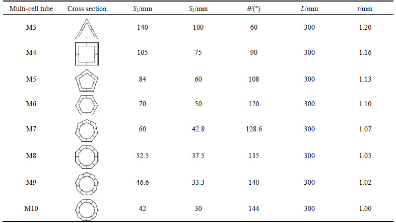
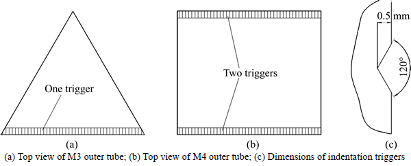
Fig. 2 Indentation triggers:
3.2 Finite element modeling
The explicit nonlinear finite element code LS-DYNA was used for the crushing simulations. The schematic diagram of the loading arrangement is shown in Fig. 3. The bottom end of the tube was fully clamped on a rigid plate. Meanwhile the free upper end is compressed by a rigid plate, which had a constant velocity and is inclining at an angle of �� to the tube��s axis. The velocity is 10m/s and the �� was varied from 0�� to 30�� in an increment of 10��. The multi-cell tube is modeled with Belytchko-Tsay 4-node shell element, with five Gauss integration points through the thickness. In the numerical analysis, two types of contacts are adopted, an automatic node-to-surface contact is used between the tube and the rigid plate; an automatic-single-surface contact is used to account for the contact of the tube itself. The static and dynamic friction coefficients are set as 0.15 for the surface contact [4].
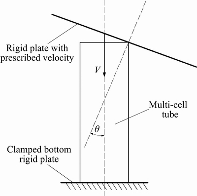
Fig. 3 Schematic of loading arrangement
The material of the tubes is aluminum alloy AA6060 T4 [4] with material properties of density ��=2700 kg/m3, elastic modulus E=68.2 GPa, Poisson ratio ��=0.3, initial yield stress ��y=80 MPa, ultimate stress ��u=173 MPa and power exponent n=0.23. Figure 4 shows the tensile stress-strain data of this material. Because the aluminum alloy is insensitive to the strain rate, the strain rate effect is not considered in the finite element modeling. In LS-DYNA, modified piecewise linear plasticity material model is selected to describe the material behavior of tubes. The rigid plate is modeled as a rigid body.
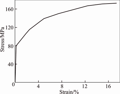
Fig. 4 Tensile stress-strain curve of AA6060 T4 [4]
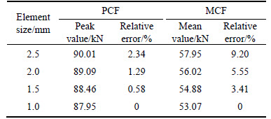
In order to calculate accurately and save computing time, a mesh convergence analysis is performed to find the optimum mesh size. Four element sizes (2.5 mm,2.0 mm, 1.5 mm and 1.0 mm) for the M10 are chosen in this analysis. Table 3 shows the peak crushing force (PCF, Fp) and mean crushing force (MCF, Fm) of four element sizes and their relative error with respect to the results of element size 1.0 mm. It is observed that there is a big difference between the results of 2.5 mm, 2.0 mm and 1.5 mm element sizes. Meanwhile, the results of 1.0 are similar and have an identical trend. To save computing time, further analysis is carried out using 1.5 mm mesh size.
Table 3 Results of mesh convergence analysis
3.3 Validation of numerical model
Because there is not yet enough reported experimental data, the numerical results of these tubes under axial loads can be validated using the theoretical formulae of mean crushing force we derived. The aluminum alloy AA6060 T4 is a material with power law hardening, so its flow stress can be calculated by Eq.(6). The value of the flow stress is 106 MPa. In order to consider the inertia and strain rate effects, a dynamic enhancing coefficient is adopted. Because AA6060 T4 is insensitive to the strain rate, the inertia is the main consideration in the identification of this coefficient. In this work, there are many triggers in each multi-cell tube, so the value of this coefficient is taken as 1.0. Table 4 lists the theoretical and numerical results of the mean crushing force under axial load.
It can be seen from Table 4 that when the coefficient of effective crushing distance is 0.72, the theoretical results are not in good agreement with the numerical results except for the M6. By adopting the effective crushing distance obtained from numerical results, modified theoretical results are obtained. The modified theoretical results are in good agreement with the numerical results, for M6, its theoretical result is underestimated, while others are overestimated. The differences are between -4.57% and 0.20%.
To further validate the finite element model in this work, the numerical results of AA6061 O multi-cell tube model is compared with the experimental results in Ref. [21]. The difference between these two finite element models is just the material. The size, material, loading and boundary conditions of tubes come from Ref. [21].
Figure 5 shows the comparison of crushing versus displacement. It can be seen that the numerical results are in good agreement with the experimental results. The key features of the experimental curves are captured by the numerical results. The differences of experimental and numerical results in both the peak crushing force and mean crushing force is less than 5%. The comparisons of deformed shapes are presented in Fig. 6, and the deformed shapes of simulation are almost completely the same as the experimental results.
Table 4 Theoretical and numerical results of crushing
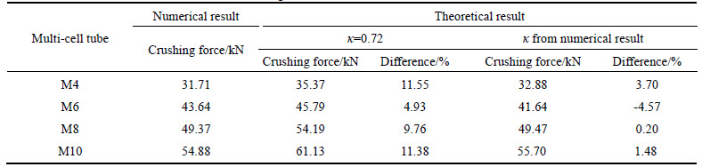
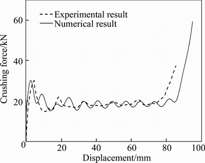
Fig. 5 Comparison of crushing force versus displacement
The comparison of experimental and numerical results shows that they are in good correlation. Therefore, the numerical model in this work is sufficiently accurate for numerical analysis.
4 Results and discussion
4.1 Crashworthiness indicators
To evaluate the crashworthiness of the multi-cell polygonal tubes properly, it is essential to predefine the crashworthiness indicators. In this work, mean crushing force (Fm) and peak crushing force (Fp) are chosen as the indicators.
 (25)
(25)
where Eint represents the total absorbed energy of multi-cell tube during the compression, and d is the crushing displacement.
By calculating the Fm, Fp, d and m, other indicators can be obtained, such as the crushing force efficiency (CFE, Ecf) and specific energy absorption (SEA, Ase).
 (26)
(26)
 (27)
(27)
In this section, the crashworthiness indicators are calculated at the crushing displacement d of 200 mm and the mass m of 0.734 kg.
4.2 Axial loading (��=0��)
Figure 7 shows the peak crushing force Fp and mean crushing force Fm of all of the multi-cell polygonal tubes at ��=0��. To better understand the crushing performances of these tubes, the deformation modes of four multi-cell polygonal tubes are shown in Fig. 10.
As we know, the M10 has the highest mean crushing force, while M3 has the lowest mean crushing force. Under the same mass, the mean crushing force increases with the number of the polygon edges from 3 to 10, but the increasing value has a decreasing trend. Meanwhile, when the number of the polygon edges increases from 3 to 10, the peak crushing force also increases, but the increasing range is less than the corresponding mean crushing force, which means that the more the edges, the larger the CLE. Thus, we can conclude that at ��=0�� the mean crushing force is more sensitive to the number of the polygon edges than the peak crushing force. The detailed numerical results of multi-cell polygonal tubes at ��=0�� are listed in Table 5.
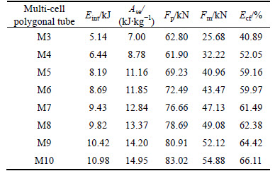
As shown in Table 5, compared with the M3, the SEA of multi-cell polygonal tubes from the M4 to M10 increases by 25.47%, 59.50%, 69.29%, 83.55%, 91.14%, 102.97% and 113.72%, respectively. At the same time, the CFE of multi-cell polygonal tubes from the M4 to M10 are 1.27, 1.45, 1.47, 1.50, 1.53, 1.58 and 1.62 times as much as that of the M3.
The deformation modes of four multi-cell polygonal tubes at ��=0�� are shown in Fig 10. All the multi-cell polygonal tubes have a stable mixed deformation mode. To be specific, for multi-cell polygonal tubes with odd number of edges, one corner angle element deforms in extensional mode and others develop in inextensional mode, and the T-shape angle elements deform in the type II mode, as defined in Ref. [7]. For multi-cell polygonal tubes with even number of edges, the corner angle elements deform in inextensional mode and the T-shape angle elements also deform in the type II mode. For these multi-cell polygonal tubes, the first folds form at the free upper end and the subsequent folds turn up at the upper end for the rest of the crushing process. As the number of polygon edges increases, the deformation modes of multi-cell tube become more stable and the number of the folding lobes also increases.
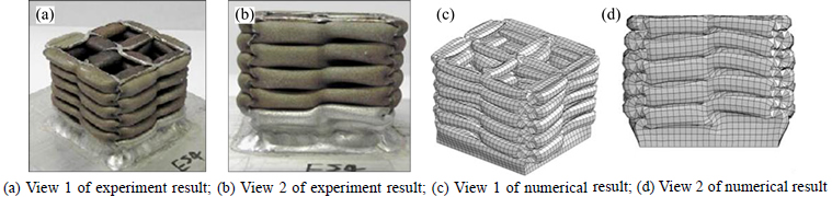
Fig. 6 Comparison of deformed shapes:
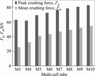
Fig. 7 Fp and Fm of multi-cell polygonal tubes at ��=0��
Table 5 Numerical results of multi-cell polygonal tubes at ��=0��
4.3 Oblique loading at small load angle (��=10��)
The peak crushing force Fp and mean crushing force Fm of all of the multi-cell polygonal tubes at ��=10�� are illustrated in Fig. 8. The deformation modes of multi-cell polygonal tubes are also shown in Fig.10.
The M10 has the highest mean crushing force, meanwhile, the peak crushing force of M10 is higher than these of other multi-cell polygonal tubes except for the M9. The M3 has the lowest mean crushing force and the peak crushing force. The mean crushing force increases with the number of the polygon edges increase. The peak crushing force increases with the number of the polygon edges varying from 3 to 9, but decreases when the number of the polygon edges changes from 9 to 10. The detailed numerical results of multi-cell polygonal tubes at ��=10��are listed in Table 6.
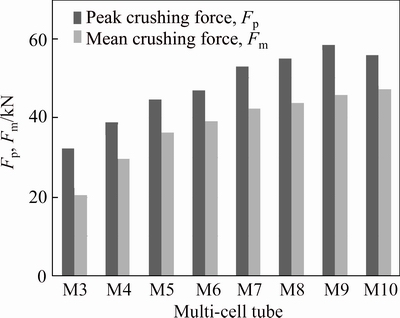
Fig. 8 Fp and Fm of multi-cell polygonal tubes at ��=10��
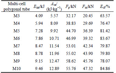
As it is shown in Table 6, the SEA of all multi-cell polygonal tubes decreases compared with ��=0��. That is mainly because under the same crushing displacement, the material participated in the plastic deformation at ��=10�� is less than ��=0��. The SEA of the M3 ranks the first in terms of 20.37% decreasing rate, the M4 has the least decreasing rate, 7.84%. The decreasing rates of other multi-cell polygonal tubes are between 10% and 15%. Because the contact region at the beginning is smaller than ��=0��, the peak crushing force also decreases, but its decreasing rate is larger than SEA. Therefore, the CFE increases by 20%-56%. The M10 has the biggest CFE of 84.86%, which is 1.34, 1.11, 1.04, 1.01, 1.06, 1.06 and 1.09 times of multi-cell polygonal tubes from M3 to M9. What is more, the SEA of the M10 is also the biggest SEA among these multi-cell polygonal tubes.
Table 6 Numerical results of multi-cell polygonal tubes at ��=10��
The deformation modes of four multi-cell polygonal tubes at ��=10�� are also shown in Fig. 10. We can see from this figure that all of the multi-cell polygonal tubes maintain a stable deformation mode, however, their deformation modes change greatly compared with their deformation modes at ��=0��. For each of the multi-cell polygonal tubes, the whole structure is tilted to the oblique loading direction during the compression.
4.4 Oblique loading at large load angle (��=20�� and 30��)
Figures 9(a) and (b) show the peak crushing force Fp and mean crushing force Fm of all of the multi-cell polygonal tubes at ��=20��and ��=30��,respectively. The deformation modes of multi-cell polygonal tubes at ��=20�� are also listed in Table 7. For the deformation modes of these tubes at ��=30�� are also global bending, which is the same as the deformation modes at ��=20��, the deformation modes at ��=30�� are not presented.
It can be observed from Fig. 9(a) that at ��=20�� the M8 has the highest peak crushing force, the M9 has the highest mean crushing force and the M4 has the lowest mean crushing force. From Fig. 9(b) at ��=30��, the M7 has the highest peak crushing force, the M9 has the highest mean crushing force and the M3 has the lowest mean crushing force. In both cases, the M3 has the lowest peak crushing force and compared with ��=0��, the peak crushing force and mean crushing force decrease for all of the multi-cell polygonal tubes. From Fig. 9, we can see that the difference in the mean crushing force of these multi-cell polygonal tubes is small, which means the energy absorption ability of these tubes is almost the same under oblique loading with a big load angle. The detailed numerical results of multi-cell polygonal tubes are listed in Table 8.
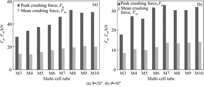
Fig. 9 Fp and Fm of multi-cell polygonal tubes:
Table 7 Deformation modes of multi-cell polygonal tubes
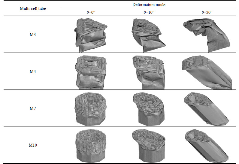
Table 8 Numerical results of multi-cell polygonal tubes at ��=20�� and 30��
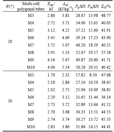
As shown in Table 8, there is a sharp decrease of the SEAs in all multi-cell polygonal tubes compared with ��=0��. At ��=20�� the SEAs are decreased by 45%-63%. At ��=30��, the SEAs are increased by 66%-85%. Except for M3, the CFEs of other multi-cell polygonal tubes are decreased by 23%-40% at ��=20�� and 25%-40% at ��=30��. Because the sharp decrease of the peak crushing force in M3, the CFE of M3 is increased by 19.28% at ��=20�� and 16.60% at ��=30��.
When ��=20�� and 30��, all of the multi-cell polygonal tubes collapse in global bending mode. Under oblique loading with large load angle, the crushing process of these multi-cell polygonal tubes can be divided into three stages. Using M8 as an example in Fig. 10, first, there is a plastic deformation area at the upper end (L=51 mm), which is close to the rigid plate; second, a plastic hinge close to the clamped end develops with the development of the compression (L=87 mm); last, the whole multi-cell tube bends around this hinge as almost a rigid body motion (L=160 mm).
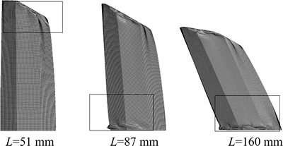
Fig. 10 Crushing process of M8
5 Conclusions
1) The mean crushing force obtained by theoretical method can be used to validate the numerical model and quickly evaluate the energy absorption ability of these tubes.
2) The numerical results under axial loading show that: all the multi-cell polygonal tubes have a stable mixed deformation mode; multi-cell tube M10 has good energy-absorption ability at ��=0��, compared with other multi-cell polygonal tubes.
3) The numerical results under oblique loading at small angle 10�� show that except for M3, other multi-cell polygonal tubes are also good at the energy absorption characteristic; under oblique loading with small load angle, all of the multi-cell polygonal tubes maintain a stable deformation mode; the multi-cell tube M10 has the biggest CFE and SEA among these eight multi-cell polygonal tubes; the SEAs of all multi-cell polygonal tubes are decreased by 8%-21% compared with ��=0��, while the CFEs are increased by 20%-56%.
4) The numerical results under oblique loading at large angle 20�� and 30�� show that under oblique loading with large load angle, all of the multi-cell polygonal tubes lose their effectiveness at energy absorption; all of the multi-cell polygonal tubes collapse in bending mode; the SEAs are decreased of all multi-cell polygonal tubes, while except for M3, the CFEs of other multi-cell polygonal tubes also decrease.
References
[1] ALEXANDER J M. An approximate analysis of the collapse of thin cylindrical shells under axial loading [J]. Quarterly Journal of Mechanics and Applied Mathematics, 1960, 13(1): 10-15.
[2] ABRAMOWICZ W, JONES N. Dynamic axial crushing of circular tubes [J]. International Journal of Impact Engineering, 1984, 2(3): 263-281.
[3] WIERZBICKI T, ABRAMOWICZ W. On the crushing mechanics of thin-walled structures [J]. Journal of Applied Mechanics, 1983, 50: 727-739.
[4] CHEN Wei-gang, WIERZBICKI T. Relative merits of single-cell, multi-cell and foam-filled thin-walled structures in energy absorption [J]. Thin-Walled Structures, 2001, 39(4): 287-306.
[5] ZHANG Xiong, CHENG Geng-dong, ZHANG Hui. Theoretical prediction and numerical simulation of multi-cell square thin-walled structures [J]. Thin-Walled Structures, 2006, 44(11): 1185-1191.
[6] QI Chang, YANG Shu, DONG Fang-liang. Crushing analysis and multiobjective crashworthiness optimization of tapered square tubes under oblique impact loading [J]. Thin-Walled Structures, 2012, 59(4): 103-119.
[7] HONG Wu, FAN Hua-lin, XIA Zhi-cheng, JIN Feng-nian, ZHOU Qing. Axial crushing behaviors of multi-cell tubes with triangular lattices [J]. International Journal of Impact Engineering, 2014, 63(1): 106-117.
[8] KASHANI M H, ALAVIJEH H S, AKBARSHAHI H, SHAKERI M. Bitubular square tubes with different arrangements under quasi-static axial compression loading [J]. Materials and Design, 2013, 51: 1095-1103.
[9] GAO Guang-jun, DONG Hai-peng, TIAN Hong-qi. Collision performance of square tubes with diaphragms [J]. Thin-Walled Structures, 2014, 80(1): 167-177.
[10] DONG Hai-peng, GAO Guang-jun, XIE Su-chao, LI Jian. Collision performance of bitubular tubes with diaphragms [J]. Journal of Central South University, 2015, 22(9): 3657-3665.
[11] NIA A A, PARSAPOUR M. An investigation on the energy absorption characteristics of multi-cell square tubes [J]. Thin-Walled Structures, 2013, 68(10): 26-34.
[12] ZHANG Xiong, CHENG Geng-dong. A comparative study of energy absorption characteristics of foam-filled and multi-cell square tubes [J]. International Journal of Impact Engineering, 2007, 34(11): 1739-1752.
[13] NAJAFI A, RAIS-ROHANI M. Mechanics of axial plastic collapse in multi-cell, multi-corner crush tubes [J]. Thin-Walled Structures, 2011, 49(1): 1-12.
[14] JUSUF A, DIRGANTARA T, GUNAWAN L, PUTRA I S. Crashworthiness analysis of multi-cell prismatic structures [J]. International Journal of Impact Engineering, 2015, 78: 34-50.
[15] QIU Na, GAO Yun-kai, FANG Jian-guang, FENG Zhao-xuan, SUN Guang-yong, LI Qing. Crashworthiness analysis and design of multi-cell hexagonal columns under multiple loading cases [J]. Finite Elements in Analysis and Design, 2015, 104: 89-101.
[16] HAN D C, PARK S H. Collapse behavior of square thin-walled columns subjected to oblique loads [J]. Thin-Walled Structures, 1999, 35(3): 167-184.
[17] SONG Jie, GUO Feng-lin. A comparative study on the windowed and multi-cell square tubes under axial and oblique loading [J]. Thin-Walled Structures, 2013, 66(3): 9-14.
[18] FANG Jian-guang, GAO Yun-kai, SUN Guang-yong, QIU Na, LI Qing. On design of multi-cell tubes under axial and oblique impact loads [J]. Thin-Walled Structures, 2015, 95: 115-126.
[19] GOEL M D. Deformation, energy absorption and crushing behavior of single-, double- and multi-wall foam filled square and circular tubes [J]. Thin-Walled Structures, 2015, 90: 1-11.
[20] ZHANG Zong-hua, LIU Shu-tian. Crashworthiness of dynamical axial crushing of polygonal thin-walled tubes [C]// SAE-C2007. Tianjin, China, 2007: 437-443.
[21] ZHANG Xiong, ZHANG Hui. Energy absorption of multi-cell stub columns under axial compression [J]. Thin-Walled Structures, 2013, 68: 156-163.
(Edited by FANG Jing-hua)
Cite this article as:
ZOU Xiang, GAO Guang-jun, ZHANG Jie, ZHOU Xi-sai, CHEN Wei, GUAN Wei-yuan. A comparative crashworthiness analysis of multi-cell polygonal tubes under axial and oblique loads [J]. Journal of Central South University, 2017, 24(9): 2198�C2208.
DOI:https://dx.doi.org/https://doi.org/10.1007/s11771-017-3628-0Foundation item: Projects(U1334208, 51405516, 51275532) supported by the National Natural Science Foundation of China; Projects(2015zzts210, 2016zzts331) supported by the Fundamental Research Funds for the Central Universities, China
Received date: 2016-01-11; Accepted date: 2016-05-16
Corresponding author: GAO Guang-jun, Professor, PhD; Tel: +86-731-82655294; E mail: gjgao@csu.edu.cn
Abstract: In order to investigate the energy absorption characteristics of multi-cell polygonal tubes with different cross-sectional configurations, firstly, the theoretical formulae of the mean crushing force under axial load for four multi-cell polygonal tubes were derived by combining the Super Folding Element theory with Zhang��s research results. These formulae can be used to validate the numerical model and quickly evaluate the energy absorption ability of multi-cell polygonal tubes. Furthermore, a comparative study on the energy absorption performance of eight multi-cell polygonal tubes under axial and oblique loads was conducted. The results show that all tubes have a stable mixed deformation mode under axial load. The multi-cell decagon tube has better energy-absorption ability compared with other tubes. When �� is less than 10��, all the tubes maintain a stable deformation mode, and the multi-cell decagon tube also has the biggest crushing force efficiency and specific energy absorption among these eight tubes; meanwhile compared with the results at ��=0��, the specific energy absorption of all tubes decreases by about 8%-21%, while the crushing force efficiency increases by 20%-56%. However, at large angles 20�� and 30��, all of the tubes collapse in bending modes and lose their effectiveness at energy absorption.
