
J. Cent. South Univ. (2012) 19: 2502-2513
DOI: 10.1007/s11771-012-1303-z![]()
Nonlinear dynamic response analysis of supercavitating vehicles
MA Zhen-yu(������), LIN Ming-dong(������), HU Fan(����), ZHANG Wei-hua(����)
College of Aerospace and Material Engineering, National University of Defense Technology, Changsha 410073, China
? Central South University Press and Springer-Verlag Berlin Heidelberg 2012
Abstract:
A finite element model for the supercavitating underwater vehicle was developed by employing 16-node shell elements of relative degrees of freedom. The nonlinear structural dynamic response was performed by introducing the updated Lagrangian formulation. The numerical results indicate that there exists a critical thickness for the supercavitating plain shell for the considered velocity of the vehicle. The structure fails more easily because of instability with the thickness less than the critical value, while the structure maintains dynamic stability with the thickness greater than the critical value. As the velocity of the vehicle increases, the critical thickness for the plain shell increases accordingly. For the considered structural configuration, the critical thicknesses of plain shells are 5 and 7 mm for the velocities of 300 and 400 m/s, respectively. The structural stability is enhanced by using the stiffened configuration. With the shell configuration of nine ring stiffeners, the maximal displacement and von Mises stress of the supercavitating structure decrease by 25% and 17% for the velocity of 300 m/s, respectively. Compared with ring stiffeners, longitudinal stiffeners are more significant to improve structural dynamic performance and decrease the critical value of thickness of the shell for the supercavitating vehicle.
Key words:
1 Introduction
The supercavitating underwater vehicle exploits supercavitation as a means to generate the cavity of water vapor at the nose of the vehicle. This cavity engulfs the complete structure and separates the vehicle hull from the water to eliminate much of the viscous drag and allows tremendous speeds to be achieved. Due to imperfect water entry, a supercavitating underwater vehicle, while moving in the forward direction, achieves stability through interaction with the fluid surrounding the cavity, which leads to a series of impacts between the vehicle tail and the cavity wall. The periodic tail-slap impacts with the interior surface of the cavity are sources of structural strains and vibrations, which result in the structural failure potentially [1].
Extensive efforts have been devoted in the past to the analysis of fluid dynamic characteristics of supercavitating vehicles, but very little research has been dedicated to the evaluation of the structural performance for supercavitating underwater vehicles under tail-slap impacts. Currently, simple discrete techniques and simplified load models are employed to explore the structural dynamic characteristics and the structural design of the supercavitating vehicle stays on the elementary level.
KULKARNI and PRATAP [2] discussed the in-flight dynamics of the supercavitating projectile, and developed a simple model used to determine the forces acting on the projectile during the impact, where a simplified expression for the added mass was provided. The numerical simulations indicated that the frequency of impacts decreased with the projectile moment of inertia, and the impact of the projectile with the cavity wall can be modelled as an impact with a rigid barrier. RUZZENE and SORANNA [3] developed a supercavitating stiffened vehicle model with a slender elastic beams in order to predict the transient response, describing the impact force to be directly proportional to the immersion depth through a constant stiffness obtained by empirical observations, and estimated the effect of periodically placed stiffening rings on the amplitude of the vibrations induced by tail-slap impacts. The presented results demonstrated the effectiveness of stiffening rings as means of reducing the vibrations and the need for stiffened configurations to be optimally designed. CHOI et al [4] simulated the flight mechanics behavior of flexible supercavitating vehicles employing RUZZENE and SORANNA��s impact force model and describing the elastic displacements through a modal superposition technique. The numerical model predicted the dynamic response of the considered class of supercavitating vehicles resulted from assigned maneuvers. In the literatures above, the comparatively appropriate models of impact of the supercavitating vehicle with the cavity wall were developed, but simple beam element models and linear numerical techniques were introduced. The dynamic analyses were conceptional consequently.
ALYANAK et al [5-6] developed a finite element model of the supercavitating vehicle with quadrilateral plate elements for vehicle skins and bar elements for stiffeners, and a thorough analysis of static strength, natural frequencies, and static buckling was performed. Following the analysis, an optimization problem was solved for each configuration, and an improvement of mass up to 18.8% could be gained. In Refs. [5-6], the proper models of supercavitating vehicles were introduced, but the static analysis was emphasized without considering the complicated dynamic conditions, so the optimal simulating results were not enough to sustain the structural design of supercavitating vehicles.
YANG et al [7-8] and ZHANG et al [9] developed numerical models of supercavitating vehicles by employing commercial finite element codes, and the structural dynamic response was performed. The numerical calculation results showed that the structural response of the supercavitating body was greatly distinct at certain frequencies and the amplitude value tended to decrease with a rise in frequencies. The results also indicated that the maximum deformation of the vehicle increased with the vehicle velocity. In Refs. [7-9], some useful conclusions and advices were proposed, but the models of supercavitating vehicles and the impact force with the cavity wall basically followed the previous researches without significant development.
In general, the analysis presented here is motivated by the need of developing the proper and accurate mathematic model to describe the structural dynamic feature of supercavitating vehicles. The objective of this work is to investigate the dynamic characteristics of supercavitating underwater vehicles and restrain the structural vibrations induced by the interactions between the vehicle and the cavity with more reasonable finite element model, impact force model, and nonlinear numerical techniques. A finite element model is developed by using 16-node shell element of relative degrees of freedom. The nonlinear structural dynamic response is performed by introducing the updated Lagrangian formulation. The numerical results provide some valuable information for the structural design of supercavitating vehicles.
2 Finite element formulation
2.1 Shell element of relative degrees of freedom
The uses of thin-walled shells were common in aerospace, mechanical, civil and marine engineering structures. Supercavitating vehicles underwent intense impact because of their high underwater velocities, which caused large displacement and deformation of shell structures. The appropriate shell element should be employed to capture the nonlinear dynamic characteristics in the finite element analysis of supercavitating vehicle structures.
The shell element of relative degrees of freedom [10-13] was a special transformation of isoparametric solid element. Bilinear functions were selected for the element geometry so that the element could serve as a convenient basis for unlimited forms of shell surfaces. Relative displacement degrees of freedom were introduced to replace the cumbersome finite rotations. Special shape functions were devised to accommodate these degrees of freedom with no sacrifice of the element isoparametric property. According to the features above, the shell element of relative degrees of freedom, which was simple and competitively accurate, served as an attractive basis for nonlinear analysis of shell structures. Supercavitating underwater vehicles were modeled using 16-node shell element of relative degrees of freedom for the structural nonlinear dynamic analysis.
Coordinate and displacement vectors of any point located in a 16-node isoparametric solid element can be expressed in terms of nodal variables as
![]() (1)
(1)
![]() (2)
(2)
where![]() , denotes the coordinate vector, and xk is the absolute coordinate vector at node k;
, denotes the coordinate vector, and xk is the absolute coordinate vector at node k; ![]() , denotes the displacement vector, and uk is the absolute displacement vector at node k. The shape functions Nk for the corner nodes are
, denotes the displacement vector, and uk is the absolute displacement vector at node k. The shape functions Nk for the corner nodes are
![]() (3)
(3)
![]() (4)
(4)
and for the middle nodes,
![]() (5)
(5)
where
![]() (6)
(6)
Nm and Nl are the interpolation functions of adjacent middle nodes of node k, and ![]() denotes the local natural coordinate vector.
denotes the local natural coordinate vector.
The relative coordinate vector![]() and relative displacement vector
and relative displacement vector![]() of 16-node shell element of relative degrees of freedom are expressed by linear combination of the absolute coordinate and displacement vectors of isoparametric solid element, as shown in Fig. 1.
of 16-node shell element of relative degrees of freedom are expressed by linear combination of the absolute coordinate and displacement vectors of isoparametric solid element, as shown in Fig. 1.

Fig. 1 Isoparametric solid element (a) and shell element of relative degrees of freedom (b)
The following equations are obtained:
 (7)
(7)
 (8)
(8)
From Eqs. (7) and (8), one can obtain the following equations:
![]() (9)
(9)
![]() (10)
(10)
where
![]() (11)
(11)
The displacement field of the shell element of the relative degrees of freedom is represented by the displacement on the shell midsurface together with the relative displacement on the shell bottom surface, without resorting to the rotation parameters. Its effectiveness and validation for geometric nonlinear problem of thin-walled structures have been verified [10-11].
2.2 Nonlinear dynamic finite element formulation
Supercavitating underwater vehicles underwent complex mechanical conditions during high-speed motion followed by large displacement and rotation, which should be treated as geometric nonlinear problem. The equilibrium equations were based on the deformed position and shape of structures, and the strain contained the quadratic term of displacement.
The geometric nonlinear analysis was based on the incremental discretized method. The nonlinear finite element equations were introduced by updated Lagrangian formulation (ULF), where all the static and kinematic variables were referred to the last updated deformed configuration [13-16].
Given the configurations of vehicles at time 0-t,![]() are the coordinate vectors of configurations at time 0, t and t+?t, respectively. Similarly,
are the coordinate vectors of configurations at time 0, t and t+?t, respectively. Similarly, ![]() and
and ![]() are the displacement vectors of configurations at time t and t+?t, respectively. The incremental displacement from time t to t+?t is expressed as
are the displacement vectors of configurations at time t and t+?t, respectively. The incremental displacement from time t to t+?t is expressed as
![]() (12)
(12)
where N is the shape function in a form of matrix, and ?d e is the incremental displacement vector of nodes in the element.
Referred to the updated deformed configuration at time t, the incremental discretized principle of virtual displacement at time t+?t is given by
![]() (13)
(13)
where ![]() and
and ![]() are Kirchhoff stress and green strain, respectively, and
are Kirchhoff stress and green strain, respectively, and ![]() is the virtual work of external loads of configuration at time t+?t.
is the virtual work of external loads of configuration at time t+?t.
The following increments are introduced as
![]() (14)
(14)
![]() (15)
(15)
where ![]() and
and![]() are incremental Kirchhoff stress and incremental green strain referred to the configuration at time t, respectively, and
are incremental Kirchhoff stress and incremental green strain referred to the configuration at time t, respectively, and ![]() is Cauthy stress at time t.
is Cauthy stress at time t.
The incremental green strain is expressed as a combination of linear and nonlinear components [9]:
![]() (16)
(16)
where
![]() (17)
(17)
![]() (18)
(18)
Substituting the coordinate and displacement expressions of shell element of relative degrees of freedom into the incremental strain as a form of matrix, one can obtain
![]() (19)
(19)
where
 (20)
(20)
where ![]()
![]()
 (21)
(21)
where ![]()
 (22)
(22)
With the linearization of the equilibrium Eq.(13), the nonlinear finite element equation is presented as
![]() (23)
(23)
where![]() and
and![]() are the linear and nonlinear components of tangent stiffness matrix, respectively, and ?d is the nodal incremental displacement vector of the whole model.
are the linear and nonlinear components of tangent stiffness matrix, respectively, and ?d is the nodal incremental displacement vector of the whole model. ![]() denotes the nodal internal force vector, and
denotes the nodal internal force vector, and ![]() is the equivalent nodal force vector of external loads of configuration at time t+?t.
is the equivalent nodal force vector of external loads of configuration at time t+?t.
![]() (24)
(24)
![]() (25)
(25)
![]() (26)
(26)
where ![]() and
and ![]() are the Cauthy stress matrix and vector of configuration at time t, respectively.
are the Cauthy stress matrix and vector of configuration at time t, respectively.
It is assumed that the mass matrix is constant, which is calculated referred to the configuration at time 0, and the effect of damp matrix is ignored. The incremental equilibrium equation for dynamic analysis is expressed as [13]
![]() (27)
(27)
where M is the mass matrix, and ![]() is the nodal acceleration vector of configuration at time t+?t.
is the nodal acceleration vector of configuration at time t+?t.
The incremental dynamic equation is solved by using of the Newmark method which is a kind of unconditional stable algorithm. Introducing the Newton-Laphson iteration method, the recursion relation of nonlinear dynamic finite element formulation is given by [13]
![]()
![]() (28)
(28)
Where ![]() ,
, ![]() and
and ![]() are the displacement, velocity and acceleration vectors of configuration at time t respectively; and ��, ?t and l denote the integration parameter, time step and number of iterations, respectively.
are the displacement, velocity and acceleration vectors of configuration at time t respectively; and ��, ?t and l denote the integration parameter, time step and number of iterations, respectively.
The iteration process is employed in every time step for implicit integration of the Newmark algorithm, and the tangent stiffness matrix must be reformed and decomposed in every iteration.
3 Applied forces of supercavitating vehicles
Under the operation conditions, the supercavitating body was moved by the hydrodynamic force FC applied to the cavitator at nose tip, the propulsive force FP at tail end, and the tail-slap impact force FI of interaction with the cavity/water interface. A schematic representation of the supercavitating underwater vehicle with the external applied forces is shown in Fig. 2.
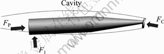
Fig. 2 Schematic representation of forces applied to supercavitating vehicle
3.1 Cavity shape and dimensions
The behavior of cavity affects the force at the nose of the vehicle, the immersion of the shell structure in the fluid, and the tail-slap force between vehicle and cavity boundary. MUNZER-REICHARDT��s model is an approximate, simplified model based on potential flow [17]. It predicts an axisymmetric cavity shape described by the following expression:
 (29)
(29)
where rc(x) is the cavity radius at location x along the centreline of cavity, while dmax and Lmax are the maximum diameter and length of cavity, respectively given by
![]() (30)
(30)
![]() (31)
(31)
where dc denotes the cavitator diameter, while CD and �� are the cavitator drag coefficient and the cavitation number, respectively.
The hydrodynamic drag and lift coefficients for a disk-type cavitator are expressed as
![]() (32)
(32)
![]() (33)
(33)
where ��c is the attack angle of cavitator, and CD0 is the drag coefficient at zero angle of attack and cavitation number.
The cavitation number is defined as
 (34)
(34)
where �� and v are the fluid density and the speed of vehicle, while p�� and pc are the ambient fluid pressure and cavity vapor pressure, respectively.
3.2 Cavitator force
The hydrodynamic force acting on the disk-type cavitator is perpendicular to the disk surface, composed of the drag force FD and the lift force FL, which are expressed as
![]() ���������������������� (35)
���������������������� (35)
![]() (36)
(36)
where A is the cavitator area.
Assume that the angle between the normal direction of cavitator and the vehicle axis is zero, the hydrodynamic force FC is equilibrated by the propulsive force FP, and both forces are considered to be applied along the vehicle axis for simplicity.
3.3 Tail-slap force
The calculation of tail-slap impact force is based on the assumption that the tail-slap impact occurs primarily in the transverse flow oriented normal to the vehicle axis, and the impact of the fluid in each cross section plane is independent of the flow exerted by a single cross section plane of vehicle over the wetted length. It is also assumed that the distance of the cavity boundary from its axis remains constant and the cavity remains fixed in space with respect to the vehicle during impact. The tail-slap force is described as a cylindrical shell structure impacting on flat and cylindrical free surfaces [18-19]. A schematic diagram of the vehicle during impact with the cavity boundary is shown in Fig. 3. The immersion depth and the wetted length of the vehicle are denoted by hp and lp, respectively, and �� is the angle between the vehicle axis and the horizontal free surface of cavity boundary.

Fig. 3 Configuration of tail-slap immersion
The tail-slap impact is described through the momentum conservation principle, which supposes that the momentum of the vehicle before impact must equal the sum of the decreased momentum of wetted vehicle and the gained momentum of the added mass of fluid after impact. Normal to the vehicle axis, the impact force acting at a cross section of the vehicle at a distance of �� from the tail end of vehicle is [2]
![]() (37)
(37)
where madd is the added mass associated with the cross section of the vehicle, and v�� is the magnitude of the velocity of the cross section under consideration.
The added mass can be calculated by the following expression [20]:
 (38)
(38)
where r is the cylindrical shell radius of the vehicle; ![]() , is the difference between the cavity radius and shell radius; �� is the immersion depth of the cross section at a distance of �� from the tail end of vehicle.
, is the difference between the cavity radius and shell radius; �� is the immersion depth of the cross section at a distance of �� from the tail end of vehicle.
The transverse velocity and acceleration at the cross section are given by
![]() (39)
(39)
![]() (40)
(40)
where![]() denotes the acceleration of the vehicle, while �� and
denotes the acceleration of the vehicle, while �� and![]() denote the angular velocity and acceleration with the nose tip of the vehicle as the reference centre of rotation, respectively.
denote the angular velocity and acceleration with the nose tip of the vehicle as the reference centre of rotation, respectively.
Substituting the value of the added mass and the transverse velocity into Eq. (1), and following the fact that![]() and
and ![]() , the expression for the impact force acting upon a single cross section of the vehicle is given by
, the expression for the impact force acting upon a single cross section of the vehicle is given by
![]() (41)
(41)
The tail-slap impact force by means of concentrated load can be obtained by integrating the specific force fI over the wetted cross sections along the vehicle axis:
![]() (42)
(42)
The tail-slap force is applied on the nodes of wetted portion of the shell structures in finite element codes by means of distributed load. For every wetted cross section of the finite element model, the impact force exerted by the single flow plane and calculated by Eq. (41) is applied on the wetted nodes of the cross section on an average.
4 Numerical results
4.1 Configuration and boundary conditions
The supercavitating underwater vehicles were modeled as shell structures, using 16-node shell elements of relative degrees of freedom, and the Kirchhoff beam elements were employed to close the heads and ends of the vehicles. The finite element model of the structure is shown in Fig. 4. Dimensions and material properties considered for the shell are listed in Table 1, where D is the cylindrical shell diameter, while L1 and L2 are the lengths of conical and cylindrical section of the shell, respectively [5, 21].

Fig. 4 Finite element model for supercavitating vehicle
Table 1 Shell material properties and geometry
![]()
The cavitator force and the propulsive force are considered as equivalent nodal forces applied on the circumferential nodes of the head and the end of the shell along the vehicle axis. The tail-slap force is applied on the nodes of the wetted portion of the shell elements by means of distributed load. The displacement degrees of freedom of the node at the center of the head of the shell are constrained to simulate the boundary conditions of the motion of vehicle in the cavity. It is assumed that the vehicle rotates around the center of the head of the vehicle on XY plane, and the initial rotational perturbation is applied to the finite element model with initial angular velocity of 1 rad/s. The lower node and the upper node at the end of the shell are chosen as the characteristic points, as shown in Fig. 4.
4.2 Dynamic response of plain shells
The dynamic responses of displacement in the Y-direction and von Mises stress of characteristic points for plain shells are presented in Figs. 5 and 6, respectively, with the vehicle velocity of 300 m/s and the thickness of shell of 3-9 mm.
As shown in Figs. 5 and 6, the dynamic responses increase remarkably under the high nonlinear loads and the structure fails readily due to the loss of stability for a thinner plain shell of the vehicle. With the thickness of 3 mm, the frequency of the response, the amplitude of displacement and stress of characteristic points increase with the time sharply. The maximal displacements in the Y-direction of characteristic points 1 and 2 are 0.15 and -0.20 m, respectively within the time of 1 s, while the maximal von Mises stresses of characteristic points 1 and 2 are 160 and 120 MPa, respectively. Obviously, a solution of divergence is obtained eventually for the thickness of 3 mm. The growth of the thickness of the shell weakens the dynamic response of supercavitating shells and enhances the structural reliability and stability significantly. With the thickness of 5 mm, the frequency of the dynamic response advances with the time but the amplitude of displacement and stress of characteristic points increase slowly, which means that the tendency of structural stability is strengthened, i.e. a quasi stability of the structure is obtained. For the thickness of 7 mm and 9 mm, the dynamic responses of displacement in the Y-direction of characteristic points exhibit periodic motions and the shell structures maintain dynamic stability despite a slight increase of the von Mises stress with the time. Compared with the thickness of 7 mm, the frequency of dynamic response decreases and the amplitude of the displacement of characteristic points inceases for the thickness of 9 mm.

Fig. 5 Displacement response for plain shells of v=300 m/s: (a1), (a2) Characteristic point 1; (b1), (b2) Characteristic point 2

Fig. 6 Stress response for plain shells of v=300 m/s: (a1), (a2) Characteristic point 1; (b1), (b2) Characteristic point 2
The supercavitating structure tends to failure of instability for a thinner shell. With the increase of the thickness of shell, the stiffness of the structure is enhanced and the structural performance and stability are improved, so the periodic motion is displayed finally. When the thickness of shell continues to increase, the frequency of dynamic response decreases and the amplitude of the displacement increases because of the increase of the mass and the inertia of the structure.
The dynamic responses of displacement in Y-direction and von Mises stress of characteristic point 1 for plain shells are presented in Figs. 7 and 8, respectively, with the vehicle velocity of 300 m/s and 400 m/s, and the thickness of shell of 3-9 mm.
With the increment of the velocity of vehicles, the dimensions of cavity increase and the drag applied on the structures rises for the considered thickness of shells for supercavitating vehicles. Therefore, the time of the contact between the vehicle and cavity wall is delayed, and at the same time, the higher amplitude of stress is obtained because of the increase of axis loads, which aggravates the structural instability.
As shown in Figs. 7 and 8, the increase of the velocity of the vehicle intensifies the dynamic response of supercavitating shells and structural instability. For the thickness of 3 mm, the maximal displacement in Y-direction and the maximal von Mises stress of characteristic point 1 increase by 130% and 110% with the velocity from 300 to 400 m/s, and the structure is destroyed more easily because of instability. For the thickness of 5 mm, compared with the velocity of 300 m/s, the frequency of the response and the amplitude of displacement and stress of characteristic points increase with the time, and the structure evolves into instability instead of quasi stability at the velocity of 400 m/s. For the thickness of 7 mm, the structural stability is enhanced to a great extent and a quasi stability of the structure is obtained with the velocity of 400 m/s. For the thickness of 9 mm, the structure maintains stability and the periodic motion exhibits with the velocity of 400 m/s as same as 300 m/s except for the increase of the the frequency and amplitude of dynamic response because of the increase of the dimensions of cavity.
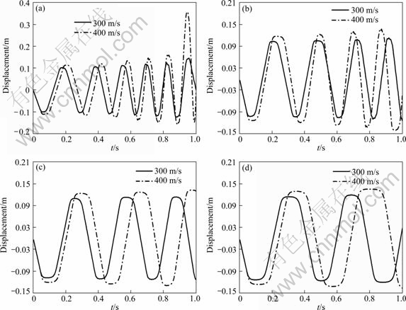
Fig. 7 Displacement response for plain shells at v=300 m/s and 400 m/s: (a) h=3 mm; (b) h=5 mm; (c) h=7 mm; (d) h=9 mm

Fig. 8 Stress response for plain shells at v=300 m/s and 400 m/s: (a) h=3 mm; (b) h=5 mm; (c) h=7 mm; (d) h=9 mm
For the considered velocity of the vehicle, there exists a critical thickness for plain shells of supercavitating vehicles. With the thickness less than the crucial value, the structures have a poor performance to resist the failure of instability. With the thickness greater than that value, the dynamic response changes periodically, and the structures keep dynamic stability. With the increment of thickness of the shell based on the critical value, the frequency of the response decreases and the amplitude increases. With the velocity of the vehicle increasing, the critical thickness for plain shells grows accordingly. According to the definition of the quasi stability, for the considered structural configuration presented, the critical thicknesses of plain shells are 5 and 7 mm for the velocity of 300 and 400 m/s, respectively. In similar manner, for the considered thickness of shell for the supercavitating vehicle, there exists a critical velocity of the vehicle. As the thickness of the shell increases, the critical velocity for the supercavitating vehicle increases.
In the structural design of supercavitating vehicles, the dynamic response of the structure must maintain stability and the frequencies of the response are as low as possible. The plain supercavitating shells have better structural stability and lower frequency at a cost of the increment of structural mass and amplitude of response. Therefore, the stiffened shells have potential advantage compared with the plain shells [3].
4.3 Dynamic response of stiffened shells
The application of stiffeners in the finite element model is simulated by changing the thickness of shell elements in the place where the stiffeners are applied. In the configurations for ring stiffeners, four ring ribs and nine ring ribs are installed in proportional spacing along the vehicle axis. In the configurations for longitudinal stiffeners, four longitudinal ribs and eight longitudinal ribs are uniformly distributed in the circumferential direction. The height of the stiffeners and the thickness of shells are 15 and 3 mm for all the configurations.
The dynamic responses of displacement in the Y-direction and von Mises stress of characteristic point 1 for ring-stiffened shells are presented in Figs. 9 and 10, respectively, with the vehicle velocity of 300 and 400 m/s.

Fig. 9 Dynamic response for ring-stiffened shells at v=300 m/s: (a) Displacement response; (b) Stress response

Fig. 10 Dynamic response for ring-stiffened shells at v=400 m/s: (a) Displacement response; (b) Stress response
As shown in Figs. 9 and 10, the application of ring stiffeners and the increment of the number of ring stiffeners decrease the dynamic response of the supercavitating shell and enhance the structural stability. For the velocity of 300 m/s, the maximal displacement in the Y-direction and the maximal von Mises stress of characteristic point 1 decrease by 25% and 17% with the shell of nine ring stiffeners compared with the plain shell. For the velocity of 400 m/s, the maximal displacement in the Y-direction and the maximal von Mises stress of characteristic point 1 decrease more sharply, and the structure exhibits periodic motions and maintain dynamic stability compared with the intense instability of the plain shell.
The ring stiffeners change the structural stiffness distribution and the vibration transmission paths along the structure. By using the ring-stiffened configuration, the structual dynamic response is weakened and the stability is enhanced, so the critical thickness of the supercavitating shell is decreased. For the higher velocity of the vehicle, the importance of the ring stiffeners for improving the dynamic performance of the shell is strengthened.
The dynamic responses of displacement in the Y-direction and von Mises stress of characteristic point 1 for longitudinal-stiffened shells are presented in Fig. 11 and Fig. 12, respectively, with the vehicle velocity of 300 and 400 m/s.
As shown in Figs. 11 and 12, the application of longitudinal stiffeners and the increment of the number of longitudinal stiffeners decrease the dynamic response of the supercavitating shell and enhance the structural stability. For the velocity of 300 and 400 m/s, the maximal displacement in the Y-direction and the maximal von Mises stress of characteristic point 1 decrease more remarkably than ring-stiffened configura- tion, and the structure exhibits periodic motions and maintain dynamic stability compared with the plain shell.
The longitudinal stiffeners reinforce the structural bend strength and flexural rigidity obviously. By using the longitudinal-stiffened configuration, the dynamic response deceases evidently and the structural stability is enhanced greatly. Compared to the ring stiffeners, longitudinal stiffeners play more significant roles in improving structural performance and decreasing critical thickness of shell for supercavitating vehicle.
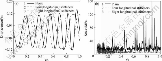
Fig. 11 Dynamic response for longitudinal-stiffened shells at v=300 m/s: (a) Displacement response; (b) Stress response

Fig. 12 Dynamic response for longitudinal-stiffened shells at v=400 m/s: (a) Displacement response; (b) Stress response
5 Conclusions
1) For the considered velocity of the vehicle, there exists a critical thickness for the plain shell of the supercavitating vehicle. With the thickness less than the crucial value, the shell structure has a poor performance to resist the failure of instability. With the thickness greater than that value, the supercavitating structure exhibits periodic motion and maintains dynamic stability. With the increment of thickness of the shell based on the critical value, the frequency of the response decreases and the amplitude increases. With the velocity of the vehicle increasing, the critical thickness for the plain shell rises accordingly.
2) For the considered thickness of the shell for the supercavitating vehicle, there exists a critical velocity of the vehicle. With the thickness of the shell increasing, the critical velocity for the supercavitating vehicle is raised.
3) With the application of stiffeners and the increment of the number of stiffeners, the dynamic response is weakened and the structural stability is enhanced. Longitudinal stiffeners are more significant to improve structural performance and decrease the critical thickness of the shell for the considered velocity of the vehicle.
References
[1] ZHANG Yu-wen. The applications of cavity theories [M]. Xi��an: Northwestern Polytechnical University Press, 2007: 113-179. (in Chinese)
[2] KULKARNI S S, PRATAP R. Studies on the dynamics of a supercavitating projectile [J]. Applied Mathematical Modelling, 2000, 24: 113-129.
[3] RUZZENE M, SORANNA F. Impact dynamics of elastic supercavitating underwater vehicles [C]// 9th AIAA/ISSMO Symposium on Multidisciplinary Analysis and Optimization. Atlanta, Georgia, 2002: 1-11.
[4] CHOI J Y, RUZZENE M, BAUCHAU O A. Dynamic analysis of flexible supercavitating vehicles using modal based elements [C]// 2003 ASME International Mechanical Engineering Congress. Washington D C, 2003: 1-12.
[5] ALYANAK E, VENKAYYA V, GRAMDHI R. Structural response and optimization of a supercavitating torpedo [J]. Finite Elements in Analysis and Design, 2005, 41: 563-582.
[6] ALYANAK E, GRAMDHI R, PENMETSA R. Optimum design of a supercavitating torpedo considering overall size, shape, and structural configuration [J]. International Journal of Solids and Structures, 2006, 43: 642-657.
[7] YANG Chuan-wu, LIU Gang, WANG An-wen. FEM analysis of structural response of supercavitating bodies [J]. Journal of Naval University of Engineering, 2008, 20: 101-104.
[8] YANG Chuan-wu, WANG An-wen. Structural response of supercavitating underwater vehicles subjected to impact loads [J]. Journal of Huazhong University of Science and Technology, 2008, 36: 129-132.
[9] ZHANG Jin-sheng, ZHANG Jia-zhong, WEI Ying-jie, CAO Wei. Structural dynamic response characteristics of supercavitating underwater vehicles [J]. Journal of Beijing University of Aeronautics and Astronautics, 2010, 36: 411-414.
[10] KANOK-NUKULCHAI W, TAYLOR R L, HUGHES T J R. A large deformation formulation for shell analysis by finite element method [J]. Computers & Structures, 1981, 13: 19-27.
[11] LI J Z, HUNG K C, CEN Z Z. Shell element of relative degree of freedom and its application on buckling analysis of thin-walled structures [J]. Thin-Walled Structures, 2002, 40: 865-876.
[12] CHEN Li-hua, CHENG Jian-gang, HUANG Wen-bin. Nonlinear dynamic analysis of shell element with a relative degree of freedom [J]. J Tsinghua Univ, 2002, 42: 228-231.
[13] WANG Xu-cheng. Finite element method [M]. Beijing: Tsinghua University Press, 2003: 406-418. (in Chinese)
[14] COOK R D, MALKUS D S, PLESHA M E. Concepts and Applications of finite element analysis [M]. Xi��an: Xi��an Jiaotong University Press, 2007: 515-552. (in Chinese)
[15] LING Dao-sheng, XU Xing. Nonlinear finite element and program [M]. Hangzhou: Zhejiang University Press, 2004: 153-187. (in Chinese)
[16] HE Jun-yi, LIN Xiang-du. Numerical method of nonlinear engineering structures [M]. Beijing: National Defense and Industry Press, 1993: 102-137. (in Chinese)
[17] AHN S S. An integrated approach to the design of supercavitating underwater vehicles [D]. Atlanta, GA, USA: School of Aerospace Engineering, Georgia Institute of Technology, 2007: 1-36.
[18] KIRSCHNER I N, KRING D C, STOKES A W. Control strategies for supercavitating vehicles [J]. Journal of Vibration and Control, 2002, 9: 219-242.
[19] DZIELSKI J, KURDILA A. A benchmark control problem for supercavitating vehicles and an initial investigation of solutions [J]. Journal of Vibration and Control, 2003, 9: 791-804.
[20] NGUYEN V, BALACHANDRAN B, VARGHESE A N. Supercavitating vehicle dynamics with non-cylindrical, non-symmetric cavities [C]// 2007 ASME International Mechanical Engineering Congress and Exposition, Seattle, Washington, USA, 2007: 1-8.
[21] AHN S S, RUZZENE M. Optimal design of cylindrical shells for enhanced buckling stability: Application to supercavitation underwater vehicles [J]. Finite Elements in Analysis and Design, 2006, 42: 967-976.
(Edited by YANG Bing)
Received date: 2011-12-09; Accepted date: 2012-05-28
Corresponding author: MA Zhen-yu, PhD Candidate; Tel: +86-731-84576482; E-mail: yuyu1031@163.com
Abstract: A finite element model for the supercavitating underwater vehicle was developed by employing 16-node shell elements of relative degrees of freedom. The nonlinear structural dynamic response was performed by introducing the updated Lagrangian formulation. The numerical results indicate that there exists a critical thickness for the supercavitating plain shell for the considered velocity of the vehicle. The structure fails more easily because of instability with the thickness less than the critical value, while the structure maintains dynamic stability with the thickness greater than the critical value. As the velocity of the vehicle increases, the critical thickness for the plain shell increases accordingly. For the considered structural configuration, the critical thicknesses of plain shells are 5 and 7 mm for the velocities of 300 and 400 m/s, respectively. The structural stability is enhanced by using the stiffened configuration. With the shell configuration of nine ring stiffeners, the maximal displacement and von Mises stress of the supercavitating structure decrease by 25% and 17% for the velocity of 300 m/s, respectively. Compared with ring stiffeners, longitudinal stiffeners are more significant to improve structural dynamic performance and decrease the critical value of thickness of the shell for the supercavitating vehicle.
