
Trans. Nonferrous Met. Soc. China 24(2014) 833-838
3D characterization and analysis of pore structure of packed ore particle beds based on computed tomography images
Bao-hua YANG1,2, Ai-xiang WU2, Xiu-xiu MIAO2, Jin-zhi LIU3
1. Information Science and Engineering School, Hunan International Economics University, Changsha 410205, China;
2. Civil and Environment Engineering School, University of Science and Technology Beijing, Beijing 100083, China;
3. College of Information Technology, Shanghai Ocean University, Shanghai 201306, China
Received 24 April 2013; accepted 9 August 2013
Abstract:
Methods and procedures of three-dimensional (3D) characterization of the pore structure features in the packed ore particle bed are focused. X-ray computed tomography was applied to deriving the cross-sectional images of specimens with single particle size of 1-2, 2-3, 3-4, 4-5, 5-6, 6-7, 7-8, 8-9, 9-10 mm. Based on the in-house developed 3D image analysis programs using Matlab, the volume porosity, pore size distribution and degree of connectivity were calculated and analyzed in detail. The results indicate that the volume porosity, the mean diameter of pores and the effective pore size (d50) increase with the increasing of particle size. Lognormal distribution or Gauss distribution is mostly suitable to model the pore size distribution. The degree of connectivity investigated on the basis of cluster-labeling algorithm also increases with increasing the particle size approximately.
Key words:
packed ore particle bed; 3D pore structure; X-ray computed tomography; image analysis;
1 Introduction
Heap leaching is an effective and economical way for treating poor ore, tailings and waste ore to extract metals, such as uranium, copper, gold and silver. The packed ore particle bed for leaching, that is ore heap, is an unconsolidated porous media. Permeability is the most important performance characteristic that affects the recovery ratio and leaching rate of valuable metals. As with any other porous media, transport properties are inherently dependent on the pore structure feature. The porosity, pore size distribution and degree of pore connectivity are three of the most important parameters used for mathematical model development to achieve fundamental relationships between pore structure and transport coefficients. In this regard, it is of importance to characterize the three-dimensional (3D) pore space in packed ore particles bed. However, since ore particle bed is packed randomly, it is unconsolidated. Furthermore, the shapes of the ore particles are irregular, so the pore structure becomes very complex. Therefore, those experimental techniques used widely in the study of many porous media, such as optical microscopy, scanning electron microscopy (SEM) and mercury intrusion porosimetry (MIP), are invalid to characterize the 3D pore structure. As a non-destructive imaging technique, X-ray computed tomography has been widely used to detect 3D geometry of the specimen in many areas in the past few decades [1-8]. This technique is very suitable for studying packed ore particles beds. It does not destroy the inner structure of the material and can directly acquire the spatial distribution of the solid phase and pores. Moreover, since ore particle beds used for heap leaching are macro porous media and the difference between the attenuation coefficients of ore particle and pore is large, the spatial and density resolutions of the selected X-ray computed tomography (CT) scanner would be sufficient.
The key purpose of this study is to obtain crucial information about pore structure in the packed ore particles beds with X-ray computed tomography and 3D image analysis. This research mainly focuses on the procedures of quantification of volume porosity, pore size distribution and degree of connectivity with Matlab. Moreover, the properties of the ore beds packed with single-sized ore particles are also analyzed.
2 Experimental
2.1 Specimen preparation
The ore particles used in this study were copper sulfide ores after screening. There were nine specimens for analysis. Each specimen was composed of single-sized particles. The particle sizes were 1-2, 2-3, 3-4, 4-5, 5-6, 6-7, 7-8, 8-9, 9-10 mm, respectively. The specimens were packed in a 60 mm (diameter)��540 mm (length) cylindrical organic glass column successively according to their particle size, the finest one was at the bottom and the coarsest one was at the top. The length of each specimen was about 60 mm. In order to locate the top and bottom of each specimen, a short thin copper wire was attached on the outside wall of the column at each interface between two specimens.
2.2 CT scanning
The specimens were scanned using a medical CT scanner, model SOMATOM Sensation 16. During scanning, the CT scanner was operated at 120 kV and 330 mA. The three-dimensional reconstructed image of the specimens in the column and its longitudinal profile obtained by the image processing system of the CT scanner itself is shown in Fig. 1. Each specimen included about 80 cross-sectional images.
2.3 Image pre-processing
In order to ensure accurate quantification of the internal structure of the tested specimens, it is necessary to conduct image pre-processing for all of the cross- sectional images, including cropping and segmentation. In this study, the image processing issues were addressed by programming based on the Matlab Image Processing Toolbox. Firstly, all the raw gray scale images were cropped into 236 pixel��236 pixel square images for further evaluation of pore structures. Once all images were properly cropped, the next critical task was to develop and implement an appropriate segmentation algorithm for the datasets to accurately confirm whether each pixel was occupied by the solid or the pore phase. Since the difference between the densities of ore particles and pores is large, the solid phase and pore phase can be distinguished by thresholding based on the gray level histograms of the images. However, this manual thresholding method based on visual inspection of the histogram may make some mistakes, namely, the pore phase may be counted as solid phase, and vice versa. To overcome the limitation of manual thresholding, Otsu��s method was used in this study [9,10], which is one of automatic threshold selection techniques. Once segmentation was complete, the serial binary images were combined in 3D for each specimen. A schematic of the raw image pre-processing procedure and volumetric reconstruction of the measured pore structure is shown in Fig. 2. The 3D binary volume was then used to calculate the volume porosity, pore size distribution, and degree of pore connectivity.
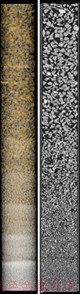
Fig. 1 Three-dimensional reconstructed image of granular ore sample and its longitudinal profile
2.4 Pore structure analysis
Volume porosity was defined as the ratio of the number of pore voxels to the total number of voxels in the 3D volume. Pore size distribution can be obtained by applying successively morphological opening with 3D structural elements (SE) of increasing size on the tested 3D volume [11-13]. Morphological opening means erosion first, then dilation. The SE used is ��ball�� with increasing radius. If a SE of 1 pixel radius is used to ��open�� the 3D binary volume, the resultant 3D volume will have only pores larger than 1 pixel in radius. The opening operation will continue until there are no pores existing in the 3D volume. For each opening, the accumulated volume fraction of the pores larger than one certain radius-r SE can be calculated. It is defined as the ratio of the sum of the voxels occupied by pore phase in the opened 3D volume and in the original 3D volume. The accumulated volume fraction of the pores smaller than radius-r SE is given by
 (1)
(1)
where S is the total number of voxels occupied by pore phase in the original 3D volume, S(r) is the total number of voxels occupied by pore phase in the 3D volume after the opening operation with a radius-r ball. Furthermore, the volume fraction of pores with one certain radius can be obtained by the difference of two successively accumulated volume fractions. This radius is called equivalent radius. It is equivalent to the radius of the maximal inscribed sphere in the pore.
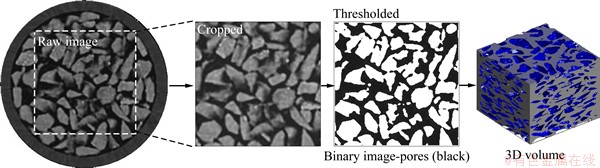
Fig. 2 Image pre-processing procedure and 3D volumetric reconstruction (particle size is 7-8 mm)
Pore connectivity is one of the most important features for pore structure of ore particles beds. For heap leaching, pore connectivity has the most significant contribution to the transport of solutions. Many researchers have investigated the pore connectivity of porous media by different calculation methods [14-17], such as coordination number. In this study, a program was developed by using Matlab on the basis of cluster-labeling algorithm, which was proposed by HOSHEN and KOPELMAN [18] and then applied by AL-RAOUSH and WILLSON [19] and ZHANG et al [20] to analyze the connectivity of pore voxels in 3D binary volume. In this algorithm only those adjacent voxels that share a common surface are identified as connected voxels. If a pore voxel makes face-to-face contact with the neighboring voxels, they are labeled with a same cluster. The main task of our program is to label all of the connected paths in the 3D binary volume with different clusters and identify which clusters are connected to both top and bottom surfaces of the specimen. The degree of pore connectivity is defined as the volume fraction of labeled pore voxels belonging to the clusters that connected to both top and bottom surfaces to the total pore voxels. The degree of pore connectivity equals one when all the pore voxels are interconnected to each other and equals zero when all of the pore clusters are isolated.
3 Results and discussion
3.1 Volumetric porosity
Figure 3 illustrates the relationship between volumetric porosity and ore particle size of the specimens. It can be seen clearly that the volumetric porosity increases with increasing the ore particle size of the aggregates. They are linearly and positively related to each other. The porosities of aggregates with coarse particles are relatively higher than those for the aggregates with fine particles. These could be a result of packing of ore particles and their irregular shape. The single-sized coarser particles were packed more loosely, thus increasing the porosity.
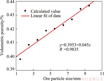
Fig. 3 Relationship between ore particle size of specimens and volumetric porosity
Figure 4 shows the comparison between the volumetric porosities and the pore area fractions obtained from image analysis of cross sections. It is noted that the average pore area fractions obtained from cross sections are in reasonable agreement with the volumetric porosities for the specimens. The correlation coefficient of them is 0.9878. It is the reason that the statistically significant number of cross-section images for each specimen is used to get its average pore area fraction.
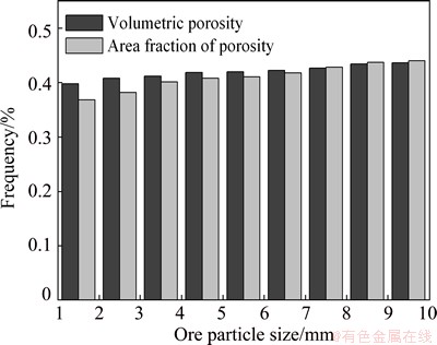
Fig. 4 Comparison of volumetric porosities and pore area fractions of specimens
3.2 Pore size distribution
Figure 5 shows the pore size distributions of the nine samples. It can be noticed that the size of the largest pores increases with increasing the ore particles size for the tested samples, indicating that the pore size distribution ranges more and more widely. The pores in those samples composed of smaller particles (samples1-5) present narrower distribution. It can be found for these five samples that the pore size distribution is skewed to the left. For an instance, more than 90% of the pores volume corresponds to pores smaller than 1.08 mm for sample 1. Few pores (less than 2%) are larger than 2 mm. Such skewed distributions often closely fit the log-normal distribution. For the other four samples, pore size distribution ranges wider since the ore particles in these samples are coarser and the pore shapes are more irregular. Compared with other models, the Gauss distribution is mostly suitable to model these processes. From the fitting data, the mean diameter can be obtained, as shown in Fig. 6. It indicates that the mean diameter of the pores increases with increasing the ore particles size for the nine samples.
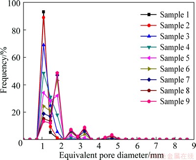
Fig. 5 Pore size distribution of samples
Figure 7 shows the cumulative frequency distribution curves of pore sizes for the nine samples. From the cumulative frequency distributions, the effective pore size (d50), which is defined as the pore size corresponding to 50% of the cumulative frequency distribution, can be obtained. It is found that the effective pore size is linearly related to the ore particle size for the tested samples and increases with the increasing of the particle size.
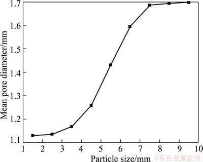
Fig. 6 Relationship between mean pore diameter and particle size of samples
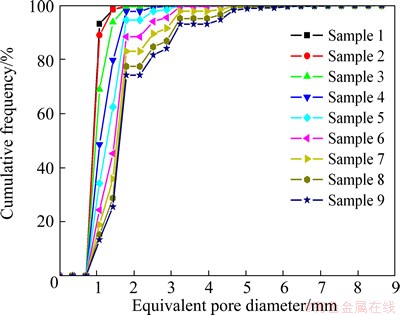
Fig. 7 Cumulative frequency distribution of pore sizes of nine samples
3.3 Pore connectivity
By means of cluster-labeling algorithm described in detail in Section 2.4, the number of pore voxels that interconnect between one surface and the opposite surface of the sample can be detected. Considering the spatial variations in the pore structure, 22 random volumes with cross-section size of 110 pixel��110 pixel were extracted from the full binary dataset to calculate the average degree of connectivity for each sample. The 22 volumes were obtained by moving the start coordinate for cropping to the center of the image from two perpendicular directions. For each random volume, it is able to estimate the degree of connectivity by dividing the number of interconnected pore voxels by the total number of pore voxels, then the average degree of connectivity can be obtained, and is shown in Fig. 8. It can be found that the connectivity of the nine samples is good, with the degree of connectivity over 99%. The degree of pore connectivity increases with the increase of ore particle size of the sample approximately.
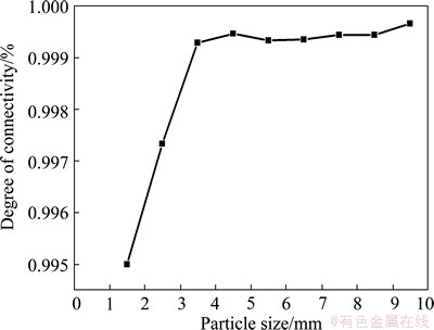
Fig. 8 Relationship between degree of pore connectivity and particle size
4 Conclusions
1) As a non-destructive experimental technique, X-ray computed tomography was successfully applied to obtaining the cross-sectional images of the pore space of packed ore particle beds. The reconstructed 3D dataset from preprocessed 2D images can be applied to characterizing the pore structure.
2) The porosity, pore size distribution and degree of pore connectivity are three of the most important parameters used for mathematical model development to achieve inherent relationships between pore structure and transport coefficients. They were successfully calculated using the in-house developed 3D image analysis programs based on Matlab.
3) For the tested nine specimens, the volume porosity, mean pore diameter, effective pore size and the degree of pore connectivity increase with increasing the ore particle size. Lognormal distribution and Gauss distribution are mostly suitable to model the pore size distribution. Cluster-labeling algorithm is significantly effective for investigating pore connectivity.
References
[1] MUNKHOLM L J, RICHARD H J, DEEN B. Soil pore characteristics assessed from X-ray micro-CT derived images and correlations to soil friability [J]. Geoderma, 2012, 181-182(7): 22-29.
[2] DEWANCKELE J, KOCK T D, BOONE M A, CNUDDE V, BRABANT L, Boone M N, Fronteau G, Hoorebeke L V, Jacobs P. 4D imaging and quantification of pore structure modifications inside natural building stones by means of high resolution X-ray CT [J]. Science of the Total Environment, 2012, 416(2): 436-448.
[3] Bhuiyan I U, Mouzon J, Forsberg F, Forsmo S P E,  M, Hedlund J. Consideration of X-ray microtomography to quantitatively determine the size distribution of bubble cavities in iron ore pellets [J]. Powder Technology, 2013, 233(1): 312-318.
[4] Zhou N, Matsumoto T, Hosokawa T, Suekane T. Pore-scale visualization of gas trapping in porous media by X-ray CT scanning [J]. Flow Measurement and Instrumentation, 2010, 21(3): 262-267.
[5] Wildenschild D, Hopmans J W, Vaz C M P, Rivers M L, Rikard D, Christensen B S B. Using X-ray computed tomography in hydrology: Systems, resolutions, and limitations [J]. Journal of Hydrology, 2002, 267(3-4): 285-297.
[6] Ashbridge D A, Thorne M S, Rivers M L, Muccino J C, O��Day P A. Image optimization and analysis of synchrotron X-ray computed microtomography (CmT) data [J]. Computers & Geosciences, 2003, 29(7): 823-836.
[7] Pierret A, Capowiez Y, Belzunces L, Moran C J. 3D reconstruction and quantification of macropores using X-ray computed tomography and image analysis [J]. Geoderma, 2002, 106(3-4): 247-271.
[8] Levitz P. Toolbox for 3D imaging and modeling of porous media: Relationship with transport properties [J]. Cement and Concrete Research, 2007, 37(3): 351-359.
[9] Gonzalez R C, Woods R E, Eddins S L. Digital image processing using MATLAB [M]. RUAN Qiu-qi. Beijing: Publishing House of Electronics Industry, 2005. (in Chinese)
[10] Wargo E A, Hanna A C, Cecen A, KalidindiS R, Kumbur E C. Selection of representative volume elements for pore-scale analysis of transport in fuel cell materials [J]. Journal of Power Sources, 2002, 197(1): 168-179.
[11] Lin C L, Miller J D. Pore structure and network analysis of filter cake [J]. Chemical Engineering Journal, 2000, 80(1-3): 221-231.
[12] Dupuy P M, Austin P, Delaney G W, SchwarzM P. Pore scale definition and computation from tomography data [J]. Computer Physics Communications, 2011, 182(10): 2249-2256.
[13] Daian J F, Fernandes C P, Philippi P C, Bellini da Cunha Neto J A. 3D reconstitution of porous media from image processing data using a multiscale percolation system [J]. Journal of Petroleum Science and Engineering, 2004, 42(1): 15-28.
[14] Armatas G S. Determination of the effects of the pore size distribution and pore connectivity distribution on the pore tortuosity and diffusive transport in model porous networks [J]. Chemical Engineering Science, 2006, 61(4): 4662-4675.
[15] Vogel H J. Morphological determination of pore connectivity as a function of pore size using serial section [J]. European Journal of Soil Science, 1997, 48(3): 365-377.
[16] Vervoort R W, Cattle S R. Linking hydraulic conductivity and tortuosity parameters to pore space geometry and pore-size distribution [J]. Journal of Hydrology, 2003, 272(1-4): 36-49.
[17] Ghassemzadeh J, Sahimi M. Pore network simulation of fluid imbibition into paper during coating II. Characterization of paper��s morphology and computation of its effective permeability tensor [J]. Chemical Engineering Science, 2004, 59(11): 2265-2280.
[18] Hoshen J, Kopelman R. Percolation and cluster distribution I. Cluster multiple labeling technique and critical concentration algorithm [J]. Physical Review B, 1976, 14(8): 3438-3445.
[19] Al-Raoush R I, Willson C S. A pore-scale investigation of a multiphase porous media system [J]. Journal of Contaminant Hydrology, 2005, 77(1-2): 67-89.
[20] Zhang Ming-zhong, He Yong-jia, Ye Guang, Lange D A, Breugel K V. Computational investigation on mass diffusivity in Portland cement paste based on X-ray computed microtomography (��CT) image [J]. Construction and Building Materials, 2012, 27(1): 472-481.
����CTͼ��Ŀ�ʯ�����ѻ����϶�ṹ��ά���������ͷ���
���1,2���Ⱞ��2��������2������֦3
1. �������⾭��ѧԺ ��Ϣ��ѧ�빤��ѧԺ����ɳ 410205��
2. �����Ƽ���ѧ ��ľ�뻷������ѧԺ������ 100083��
3. �Ϻ������ѧ ��ϢѧԺ���Ϻ� 201306
ժ Ҫ���о�����ͼ������Ŀ�ʯ�����ѻ����϶�ṹ��ά���������ķ������̡�����X��CT�����ֱ��ȡ��1~2��2~3��3~4��4~5��5~6��6~7��7~8��8~9��9~10 mm�Ŀ�ʯ�������ɵĵ������ѻ���Ķϲ�ͼ����Matlab���п�������ά�ع���ͼ����������㲢�������϶�ʡ���϶�ߴ�ֲ��Լ���϶��ͨ��3����������������������ѻ�������϶�ʡ�ƽ����϶�ߴ����Ч��϶�ߴ�(d50)���ſ�����������������ӣ���϶�ߴ���Ӷ�����̬�ֲ�����̬�ֲ������ھ������㷨�õ��Ŀ�϶��ͨ��Ҳ�������ſ�����������������ӡ�
�ؼ��ʣ���ʯ�����ѻ��壻��ά��϶�ṹ��X��CT��ͼ�����
(Edited by Hua YANG)
Foundation item: Projects (50934002, 51074013, 51304076, 51104100) supported by the National Natural Science Foundation of China; Project (IRT0950) supported by the Program for Changjiang Scholars Innovative Research Team in Universities, China; Project (2012M510007) supported by China Postdoctoral Science Foundation
Corresponding author: Ai-xiang WU; Tel: +86-10-62333563; E-mail: wuaixiang@126.com
DOI: 10.1016/S1003-6326(14)63131-9
Abstract: Methods and procedures of three-dimensional (3D) characterization of the pore structure features in the packed ore particle bed are focused. X-ray computed tomography was applied to deriving the cross-sectional images of specimens with single particle size of 1-2, 2-3, 3-4, 4-5, 5-6, 6-7, 7-8, 8-9, 9-10 mm. Based on the in-house developed 3D image analysis programs using Matlab, the volume porosity, pore size distribution and degree of connectivity were calculated and analyzed in detail. The results indicate that the volume porosity, the mean diameter of pores and the effective pore size (d50) increase with the increasing of particle size. Lognormal distribution or Gauss distribution is mostly suitable to model the pore size distribution. The degree of connectivity investigated on the basis of cluster-labeling algorithm also increases with increasing the particle size approximately.
