
J. Cent. South Univ. (2017) 24: 1073-1081
DOI: 10.1007/s11771-017-3510-0

Trajectory tracking of powered parafoil based on characteristic model based all-coefficient adaptive control
TAN Pan-long(̴����)1, SUN Qing-lin(������)1, JIANG Yu-xin(������)1,
ZHU Er-lin(�����)2, CHEN Zeng-qiang(����ǿ)1, HE Ying-ping(��Ӧƽ)3
1. Intelligent Robots Key Lab of Tianjin, College of Computer and Control Engineering,
Nankai University, Tianjin 300071, China;
2. School of Electricity & Information Engineering, Jiangsu University of Technology, Changzhou 213001, China;
3. Hongwei Aircraft Limited Corp., Xiangyang 441022, China
 Central South University Press and Springer-Verlag Berlin Heidelberg 2017
Abstract:
One of the primary difficulties in using powered parafoil (PPF) systems is the lack of effective trajectory tracking controllers since the trajectory tracking control is the essential operation for PPF to accomplish autonomous tasks. The characteristic model (CM) based all-coefficient adaptive control (ACAC) designed for PPF systems in horizontal and vertical trajectory control is proposed. The method is easy to use and convenient to adjust and test. Just a few parameters are adapted during the control process. In application, vertical and horizontal CMs are designed and ACAC controllers are constructed to control vertical altitude and horizontal trajectory of PPF based on the proposed CMs, respectively. Result analysis of different simulations shows that the applied ACAC control method is effective for trajectory tracking of the PPF systems and the approach guarantees the transient performance of the PPF systems with better disturbance rejection ability.
Key words:
1 Introduction
Recently, flexible vehicles have gradually become a research hot topic in the aerospace field [1,2]. Ram-air parafoil is a new kind of flexible wing vehicle developed from traditional umbrella-like parachute, which derives lift from a ram-air inflated canopy. The main characteristics of the parafoil are its steer-ability, stability and portability. Parafoil systems are lightweight and are compact before deployment. They fly at a low speed and can provide a soft landing for sensible facilities. The dynamics of the parafoil are sufficiently slow so that it is able to track a desired trajectory precisely and attains accurate ground impact. The development of large size ram-air parafoil, global positioning system (GPS), miniaturized powerful sensors and micro control units (MCUs) enable the implementation of fully autonomous aerial cargo delivery systems. The autonomous operating parafoil system is considered an adequate means to precisely deliver aerial cargo to almost everywhere on the ground [3]. Parafoils find widely use in unmanned aerial vehicle (UAV), crew return vehicle (CRV), guided parafoil air drop system (GPADS) and sports activities due to their good gliding as well as control characteristics.
In order to use the parafoil UAV functions not as a glider, but rather an aircraft with thrust being applied to the system, namely, it is a powered parafoil (PPF), which is composed of a parafoil and a suspended payload body equipped with an engine and a propeller [4], as shown in Fig. 1. Typically, the PPF flies around the speed 11.6-14.3 m/s, and cannot be at any other speed. Actually, several autonomous PPFs have been studied and developed for various purposes, such as land observation, surveillance and reconnaissance of the ground circumstances. The low flight speed of the PPF makes it suitable for observation in a small area with high accuracy. Furthermore, the PPF is safe and survivable in case of engine fault because it can keep stable flight without thrust and can be guided to the safe area. Even the failure of the control system will not derive severe damage to the whole system because of the landing capabilities of the parafoil.
The PPF system is a complex nonlinear system and is subject to wind disturbance. Modeling dynamics of a PPF are more complicated than a rigid-body aircraft [5]. Substantial research has been conducted on the dynamics
of parafoils and payloads, beginning with that of WARE and HASSELL [6], who investigated ram-air parafoils in a wind tunnel. Flight test data of NASA��s X-38 parafoil program, which researched the lateral and longitudinal aerodynamics for large-scale parafoils, have recently been reported [7, 8]. Parafoil dynamic model complexity varies significantly in literature with different degrees-of- freedom (DOF). Simple three- and four-DOF models are proposed by JANN [9] based on ALEX parafoil flight test data. More complicated models with higher DOF are then presented. MORTALONI et al [10] focused on six-DOF dynamic model and showed their result, which treated the parafoil and payload as a rigid connection. SLEGERS and COSTELLO [11] considered the relative motions between the parafoil and the payload and established a nine-DOF dynamic model. Following consideration of the engineering practice of the PPF system, WATANABE and OCHI [4] reduced the dynamic model to eight-DOF.
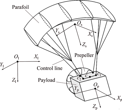
Fig. 1 Powered parafoil and relevant coordinates
The research on the control of parafoil dynamics at present mainly examines the six-DOF model of the gliding parafoil systems without a propeller. SLEGERS and COSTELLO [5] applied the model predictive control method (MPC) to control the parafoil-payload system. But they deal with the horizontal trajectory tracking problem based on the six-DOF model and the altitude control is not considered. A hybrid algorithm of fuzzy control and predictive control method was proposed in Ref. [12] in flight path tracking of the parafoil system. GAO et al [13] tackled the problem of parafoil trajectory tracking by using data expanded ADRC, which achieved some positive result. In both Refs. [12] and [13] the simulation was proposed based on the six-DOF parafoil model and only the horizontal trajectory tracking problem was concerned.
The work reported here builds a characteristic model (CM) based all-coefficient adaptive control (ACAC) strategy for the PPF aircraft. Two control channels are constructed to control vertical and horizontal trajectory of the PPF. In order to improve simulation accuracy, a dynamic model with eight-DOF of the PPF system is presented and used to support simulation analysis in this work.
2 Dynamic modeling of PPF
The PPF system is presented with eight-DOF in this work, including three inertial position components of the parafoil mass center, three Euler orientation angles of the parafoil, and relative pitching and yawing motions between the parafoil and the payload. In order to facilitate the analysis, some reasonable hypotheses are made as follows [14].
1) After the parafoil has been inflated completely, its aerodynamic configuration keeps steady without maneuvering;
2) The mass center of the parafoil overlaps the aerodynamic pressure center, but does not overlap the gravity center;
3) The lift force of the payload is ignored only considering its aerodynamic drag force;
4) The ground is plane.
2.1 Coordinate systems
In this work, three independent coordinate systems are utilized to formulate the dynamic model of the PPF, including the inertial coordinate system  , the parafoil-fixed coordinate system
  and the payload-fixed coordinate system
  . , and are shown in Fig.1 and are defined as (XI, YI, ZI), (Xs, Ys, Zs) and (Xp, Yp, Zp), respectively. The XI-axis, YI-axis and ZI-axis form a right-hand inertial coordinate system. The direction of XI-axis is forward and the direction of ZI-axis is downward. The XI-axis and YI-axis form a horizontal plane. The origin and the positive direction of XI-axis of are set appropriately according to the parafoil-fixed coordinate system. The origin Os of the parafoil-fixed coordinate system is chosen at the center of gravity (CG) of the parafoil and the Zs-axis is defined in the direction from Os to Op, the origin of the payload-fixed system and the CG of the payload. The Xs-axis is perpendicular to the Zs-axis in the symmetry plane of the payload and the positive direction of the Xs-axis is taken forward. The Ys-axis is designed so that the payload-fixed coordinate system forms a right-hand coordinate system. The Xp-axis is taken forward along the thrust direction, and the Xp-axis is taken downward, perpendicular to the Xp-axis in the symmetry plane. The selection of Yp-axis makes a right-hand coordinate system.
2.2 Motion equations of payload
The payload is treated as a rigid body with a regular shape so that the momentum and the moment of momentum method are applied to formulate motion equations of the payload. The forces acted on the payload are the aerodynamic force, the gravity, the tension of the suspension line and the thrust by propeller. The gravity and thrust are assumed to be applied to the mass center of the payload. The moments caused by the gravity and thrust are ignored. The motion equations are described as
 (1)
(1)
 (2)
(2)
where Vp=[u v w]T and Wp=[p q r]T are the vectors of velocity and angle velocity of the payload mass center, respectively; F and M with subscript p are the forces and moments acted on the payload, respectively. The superscript aero denotes the aerodynamic force; t denotes the tension of suspension lines; G represents the gravity; th represents the thrust and f represents the friction. Pp and Hp denote the momentum and the moment of momentum of the payload, respectively, and are formulated as
Pp=mpVp (3)
Hp=JpWp (4)
where mp denotes the mass of the payload and Jp is the matrix moment of inertia of the payload.
2.3 Motion equations of parafoil
This section is described under the consumption that the parafoil has been completely inflated in the air. The forces performed on the parafoil include the aerodynamic force, the gravity and the tension of lines.
 (5)
(5)
 (6)
(6)
where Vs and Ws are the vectors of velocity and angle velocity of the parafoil mass center and the subscript s represents the parafoil coordinate system. Equations (1) and (2) are similar to Eqs. (5) and (6) given above.
The parafoil is a kind of flexible flight wing which is a lightly loaded vehicle. It is significantly important to take apparent mass into consideration when computing the parafoil motions. Therefore, the performance of the apparent mass and the moment of inertia caused by the apparent mass are considered when calculating the momentum Ps and the moment of momentum Hs.
 (7)
(7)
Or to facilitate the derivation, the equation can also be rewritten as
 (8)
(8)
where Aa and Ar represent the inertia matrix of the apparent mass and the real mass, respectively; Ai(i=1, 2, 3, 4) denotes a third-order sub-matrix of [Aa+Ar].
2.4 Constraint of velocity and angular velocity
The parafoil and payload both have a six-DOF model. But the velocities and the angular velocities of the parafoil and the payload are not independent from each other. Let C be the middle of the two connection points between the parafoil and the payload. Then, the constraint of velocity and angular velocity satisfies the equation:
 (9)
(9)
where Lp-c and Ls-c denote the distance from the mass center of the payload to C and the distance from the mass center of the parafoil to C, respectively.
As for the relative rotation of two bodies, the equation can be obtained as
 (10)
(10)
where ��s=[0 0 ��r] and ��p=[0 �� 0] stand for the relative yaw angle and the relative pitch angle, respectively.
2.5 Dynamic model of PPF system
Let  be the state vector of the dynamic model of the PPF system. Then x is a 14��1 vector with eight independent parameters. Combining Eqs. (1), (2), (5), (6), and (9), the dynamic model of the PPF is organized as
 (11)
(11)
The details of the model are shown below.
 (12)
(12)

 (13)
(13)
 (14)
(14)
 (15)
(15)

 (16)
(16)


 (17)
(17)
 (18)
(18)
 (19)
(19)
In Eqs. (11)-(19), the symbol  means the transference matrix from one coordinate system to another. And
  is the inverse matrix of . The coefficient k in Eq. (12) is a constant determined by the nature of the system.
  and
and  denote the moment caused by spring and damper.
  and
and mean the distance between the two connection points expressed in the parafoil-fixed coordinate system and the payload-fixed coordinate system. Cm is given as
 (20)
(20)
where the symbol s�� stands for sin�� and the symbol c�� stands for con��.
A brief introduction for dynamic modeling of the PPF system is presented in this section and the state equation is given as a conclusion at the end. The detailed modeling procedure is shown in Ref. [14], in which we focused on the modeling problem of the PPF system.
3 Characteristic model based all-coefficient adaptive control
Characteristic model based all-coefficient adaptive control was first proposed in 1980s [15,16]. In the preceding two decades, significant progresses in theories along with its integration with adaptive control design have been made, and allowed several new engineering applications to be implemented [15-17]. Unlike former theory based control algorithms, the characteristic model based all-coefficient adaptive control is an engineering oriented control method, which requires to estimate and adapt a few parameters. The explicit model of the system is not a necessity in its application. The characteristic of such an approach guarantees the transient performance of the closed-loop system. Therefore, the practical difficulties in the application of adaptive control laws can be overcome to a further extent [18]. In fact, the characteristic model based all-coefficient adaptive control has been implemented in various fields, particularly in the area relative to aircrafts and satellites [17].
In the application of the CM based ACAC method, a CM of the plant to be controlled is established at first. The ACAC is designed based on the proposed CM.
3.1 Characteristic model
The CM used in the ACAC theory is a dynamic model designed to represent the practical dynamic model of the plant. The CM is easier to use compared to practical dynamic models, but it is not just simplified from them. The key idea of the characteristic modeling is to model the plant based on the control performance requirements as well as the dynamic characteristics of the plant.
The characteristic model contains the following important features [15].
1) The same input leads to the same output for the plant and its CM.
2) The specific form and the order of the CM mainly rely on the control performance requirements.
3) The structure of the CM is simpler than that of its original dynamic equations, and thus is easier to use in engineering applications.
4) It is essentially different from the conventional reduced-order models, and it compresses the information of the system dynamics into several characteristic variables. Within the bandwidth of the control system, no information is lost.
In general, a second-order CM is sufficient for maintaining position and tracking the trajectory of the control system. According to requirements of the control problem at hand,the CMs for each variable of the PPF system, the vertical and horizontal dynamics, are described by the following time-varying diffierential equation [15].
 (21)
(21)
where y(k) and u(k) denote the output and input signals of the system, respectively; fi(k) (i=1, 2) and g0(k) are slow time-varying coefficients of CM.
The time-varying coefficients f1, f2 and g0 belong to the convex set below.
 (22)
(22)
where ��max=1/Tmin and Tmin is the minimum time constant of the system; b0 denotes the input gain [19].
The parameters used in the CM, f1(k), f2(k) and g0(k), are slow time-varying according to the dynamics of the controlled plant and will be estimated online. To proceed the control design, we define the parameter vectors as follows:
 (23)
(23)
 (24)
(24)
Then, Eq. (20) can be rewritten in the follow compact form:
 (25)
(25)
The gradient correction parameter estimation method is adopted to update the parameter vector:

 (26)
(26)
where ��i (i=1, 2) are constants preventing the system output from being zero and 0<��1<1, ��2<0;  is projection operator ensuring the estimated parameters to be held in the range defined by Eq.(21).
It is necessary and reasonable to impose constraints on the parameters of the system and it is also the key feature of the CM based ACAC.
3.2 All-coefficient adaptive control
The output of all-coefficient adaptive control is constructed as
 (27)
(27)
where u0(k), uG(k), uI(k) and uD(k) are the tracking controller, the golden-section controller, the logic integral controller and the logic diffierential controller, respectively.
The detailed u0(k), uG(k), uI(k) and uD(k) are given as follows.
 (28)
(28)
 (29)
(29)
 (30)
(30)
 (31)
(31)
Here, the e(k) is defined as
 (32)
(32)
where yr(k) and y(k) denote the tracking target function and system output; f1(k), f2(k) and g0(k) are time-varying coefficients of the CM; �� is a tunable parameter.
The parameters l1 and l2 are constants expressed as l1=0.382, l2=0.618. That is the reason why the controller uG(k) is named golden-section controller. The parameters kI and kD are defined as
 (33)
(33)
 (34)
(34)
where kI1>>kI2>0, cD>0, lD>0 are constants; lD is a positive integer.
Additionally, the four parts of the ACAC control law are optional except the golden-section controller. The designing of the all-coefficient adaptive controller structure depends on the engineering practice. The golden-section controller is essential as it is the key part of ACAC. The other parts are selected or given up as necessary.
It is easy to tell that the all-coefficient adaptive control is essentially diffierent from conventional adaptive control according to the ACAC control law. The estimated parameters used in designing ACAC are the coefficients of the CM. As a result, the constraints on the unknown parameters of the system dynamics in nonlinear adaptive control are diminished. It has been proven in Refs. [20] and [21] that the ACAC method guarantees the transient property and robust stability of the control system.
4 Designing of controllers
According to the engineering practice, two control channels are designed to control vertical and horizontal trajectory of the PPF system. The details are shown in Fig. 2.
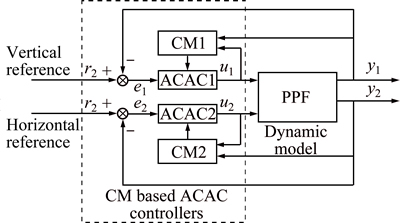
Fig. 2 Control block diagram
The symbols y1 and y2 represent the vertical and horizontal positions of the PPF, respectively; u1 is the thrust provided by powered propeller and u2 is the deflection of the parafoil. CM1 and CM2 denote the computed CM of the vertical and the horizontal dynamic model, respectively. The CM1 is obtained based on the thrust and the vertical altitude and the CM2 is obtained based on the deflection and the horizontal fly direction. The controller ACAC1 is utilized to control the vertical altitude while ACAC2 is utilized to control the horizontal trajectory.
4.1 Vertical altitude control
It has been introduced in a former section that the ACAC method contains four parts, the tracking controller, the golden-section controller, the logic integral controller and the logic diffierential controller. All the four parts are not all necessary in ACAC, with the exception of the golden-section controller. The structure of the ACAC is determined by the engineering practice. According to the requirements of the PPF vertical altitude control problem, the vertical altitude controller is selected to consist of three parts, the golden-section controller, the logic integral controller and the logic diffierential controller.
u1=uG+uI+uD (35)
The ACAC is a kind of error-driven algorithm. The input of the ACAC controller is the calculated vertical error. In this section, the error means the difference between actual altitude and the desired altitude. The error is formulated by
e1=r1+y1 (36)
where r1 and y1 mean the desired altitude and the actual altitude of the PPF, respectively.
4.2 Horizontal position control
According to the inherent characteristic of the horizontal position control problem, the structure of the horizontal position controller is defined as follows:
u2=u0+uG+uD+uI (37)
The horizontal position controller consists of all the optional parts.
Compared with calculating the vertical error, obtaining the horizontal error proves more complicated. The horizontal error consists of two parts. The first is the direct distance from the PPF to the desired trajectory in horizontal plane. It is obtained by using the formula for the distance from point to line. The second is the error between the flight direction of the PPF and the direction of the desired trajectory line. In order to unify the unit of the horizontal error, the distance error unit is transformed to radian by applying arc tangent function. The horizontal error is formulated as
e2=r2-y2=��1-��2+atan(d/ke) (38)
where r2 and y2 denote target point and actual horizontal position of the PPF, respectively; ��1 and ��2 denote the fly direction of the PPF and the desired target direction, respectively; ke is a tunable factor and d represents the distance error.
5 Simulation analysis
The simulation experiment is conducted based on a certain type of PPF. The parafoil and payload system applied in the testing is shown in Fig. 1 with the physical parameters in Table 1. The ability of the PPF to follow a path by utilizing ACAC controllers will be analyzed in the following section.
Table1 Physical parameters of applied PPF
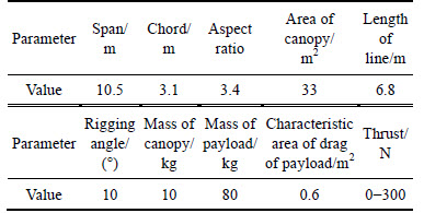
The initial position of the PPF system is (0, 0, 500)m in the inertial coordinate system and the initial velocity is set to be Vc=[14.902.1]T m/s.
5.1 Following circular trajectory
The desired trajectory to be followed is set to be a circle in the horizontal plane with a fixed altitude. A short straight line is added to the circle for the PPF to reach steady status from initial state. It shows in Figs. 3 and 4 that the PPF starts from the location at (0, 0, 500)m incoordinate system. After a period of gliding, the PPF follows the trajectory of the desired circular trajectory. As the PPF is a kind of light aero vehicle, dynamic performance of the PPF with wind disturbance is also considered in this work. Wind disturbance contributes to the relative velocity of the PPF and the air, while the lift and drag forces are proportional to the relative velocity. The wind disturbance extends the settling time of the horizontal performance. A steady 3 m/s wind along x-axis expressed in is added to PPF system as an external disturbance in simulation. Figures 3 and 4 present the PPF horizontal and vertical trajectory tracking performance based on different controllers. Comparisons between PID and ACAC controllers are also presented at the same time.
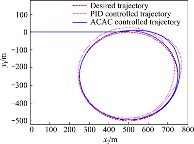
Fig. 3 Actual and desired horizontal trajectory with wind disturbance
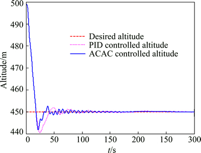
Fig. 4 Actual and desired altitude with wind disturbance
Figure 3 shows trajectory tracking results of PID controller and ACAC controller in the horizontal plane. It can be observed from it that the performance of the ACAC controller outperforms the PID controller with less settling time and lower overshoot. When the PPF is controlled by ACAC controller, the maximum tracking error at the beginning appears at 50 s with the error value of 0.41, while the maximum tracking error of the PID controller is 0.49. According to another criterion, mean square error (MSE), the horizontal ACAC controller with a horizontal distance MSE value of 13.45 m2 is superior to the PID controller with an MSE value of 41.28 m2. On the other hand, the maximum distance error of the PID controlled system is 19.5 m when the PPF is flying along the wind direction and that of the ACAC controlled system is 3.2 m. The ACAC controller shows better disturbance rejection ability than the PID controller with less tracking error.
The similar conclusion is obtained according to Fig. 4, which shows that the overshoot of the ACAC controller is 7.5 m and the overshoot of PID controller is 9.8 m. The altitude MSE of the ACAC controller is 1.63 m2 and that of PID controller is 3.17 m2. And the ACAC controller also reveals less response time and settling time. Therefore, it is concluded from Figs. 3 and 4 that the ACAC method is superior to PID under the same condition. Both Figs. 3 and 4 confirm that the ACAC method contributes to the improvement of the transient performance. The performance of the PPF with ACAC controllers obtained less response time and lower overshoot.
Figures 5 and 6 denote the control sequence of deflection and thrust of the PPF system, respectively. The deflection interacts with the thrust because of the coupling between the horizontal and vertical movement. In fact, characteristic model treats the coupling fact as a kind of inherent characteristic. Thus, the horizontal and vertical ACAC controllers can be designed and applied separately, regardless of the coupling factor.
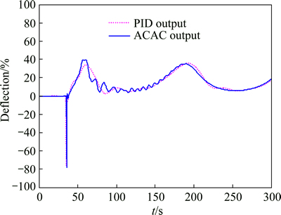
Fig. 5 Deflection output of horizontal controllers with wind disturbance
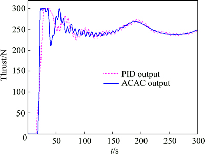
Fig. 6 Thrust output of vertical altitude controllers with wind disturbance
It also can be concluded from Figs. 5 and 6 that deflection and thrust present periodic oscillation under the effect of the wind disturbance.
5.2 Following rectangular trajectory
The desired horizontal trajectory in this section consists of a straight line and a rectangle in the horizontal plane with a fixed altitude and is shown in Fig. 7 in red line. Determined by the PPF��s inherent characteristics, it is impossible for the PPF to track trajectories with sharp corners without tracking error. Hence the overshoot is inevitable when PPF is tracking a right angle corner, as shown in Fig. 7.
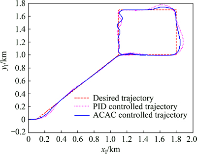
Fig. 7 Actual and desired horizontal trajectory with wind disturbance
It��s even more difficult to control the PPF when wind disturbance is added to the system while the PPF is tracking a rectangle. The relative velocity between the PPF and the air decreases when the PPF is along wind direction and vice versa. It is a challenge to keep the PPG flying along the desired path with the changing of lift and drag forces caused by the changing of relative velocity. Simulation results are presented in Figs. 7 and 8 when 2 m/s wind along the positive direction of y-axis of  is added. The same conclusion that the ACAC is superior to PID as concluded in former section can be concluded in the comparison presented in Figs. 7 and 8.
As shown in Fig. 7, the main performance difference between the PID controller and the ACAC controller lies in the turning overshoot. When the PPF is tracking a right angle along the wind direction, tracking performance of the PID controller reveals larger overshoot while the ACAC controller is able to eliminate tracking error in a short time with less overshoot. It is observed that the overshoot of the ACAC controller with a value of 51 m is better than that of PID controller with a value of 95 m. And by calculating the MSE, the horizontal distance MSE of the ACAC controller is 192.99 m2 and the MSE of the PID controller is 278.54 m2.
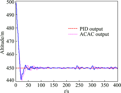
Fig. 8 Actual and desired altitude with wind disturbance
Unlike orbiting a circle, the deflection and thrust will not stay steady when the PPF is tracking the desired trajectory with corners. As shown in Fig. 9, deflection changes greatly to ensure that the PPF flies to the right direction to eliminate tracking error when the target point is changed. The changing of the flight direction affects the dynamic balance of the PPF system. Then, the thrust is recalculated to adapt the changing of the altitude. It can be observed from Fig. 8 that the altitude vibrates in a small range under the control sequence of the thrust shown in Fig. 10. The altitude MSE of the ACAC controller is 1.84 m2 and that of the PID controller is 3.53 m2.
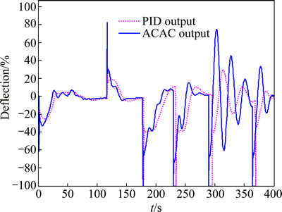
Fig. 9 Deflection output of horizontal controllers with wind disturbance
According to the comparisons and analysis, the general conclusion is that the ACAC method contributes to optimizing transient performance and reducing settling time. And it obtains better performance in application compared to PID. The disturbance rejection ability of the ACAC controllers outperforms the PID controllers at the same time.
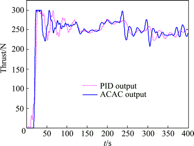
Fig. 10 Thrust output of vertical altitude controllers with wind disturbance
6 Conclusions
CM based ACAC is an engineering-oriented control method which makes it a unique control theory. CM is a kind of simple and easy-to-use dynamic model which consists of a few parameters and contains all important features of the system dynamics. CM is simple in its form, but it is different from the simplified and reduced order dynamic models. The explicit model of the plant is not a necessity in the application of the ACAC controllers because of the CM. Therefore, the practical difficulties in the application of the adaptive control laws can be overcome to a further extent.
The main conclusion obtained in this work is that the CM based ACAC is superior to other control methods such as PID. The work reported here employs the ACAC for autonomous control of the parafoil and payload system. To support the flight control law, horizontal and vertical CMs are designed and the coefficients of the CMs are estimated using gradient correction parameter estimation method during flight. Two kinds of desired trajectories, circle and rectangle, are used in the simulations and the results are presented. Two exemplar tests are performed to show that the CM based ACAC is an effective way to control the PPF system autonomously, despite the wind disturbance. It is concluded that the ACAC contributes to a decrease in settling time and overshoot, improves the transient performance and shows greater disturbance rejection ability.
References
[1] ZHANG Ming, NIE Hong, ZHU Ru-peng. Stochastic optimal control of flexible aircraft taxiing at constant or variable velocity [J]. Nonlinear Dynamics, 2010, 62(1, 2): 485-497.
[2] LI Chun, LU Zhi-hui, HUANG Wei, SHEN Chao. Guidance navigation & control system for precision fix-point homing parafoil [J]. Journal of Central South University: Science and Technology, 2012, 43(4): 1331-1335. (in Chinese)
[3] ROGERS J, SLEGERS N. Robust parafoil terminal guidance using massively parallel processing [J]. Journal of Guidance, Control, and Dynamics, 2013, 36(5): 1336-1345.
[4] WATANABE M, OCHI Y. Modeling and simulation of nonlinear dynamics of a powered paraglider [C]//AIAA Guidance, Navigation and Control Conference and Exhibit. 2008, 7418: 1-16.
[5] SLEGERS N, COSTELLO M. Model predictive control of a parafoil and payload system [J]. Journal of Guidance, Control, and Dynamics, 2005, 28(4): 816-821.
[6] WARE G M, HASSELL J L. Wind-tunnel investigation of ram-air inflated all-flexible wings of aspect ratios 1.0 to 3.0 [R]. NASA TMSX-1923, 1969.
[7] IACOMINI C S, CERIMELE C J. Lateral-directional aerodynamics from a large scale parafoil test program [C]//AIAA Modeling and Simulation Technologies Conference. Toulouse, France, 2000: 218-228.
[8] IACOMINI C S, CERIMELE C J. Longitudinal aerodynamics from a large scale parafoil test program [C]//AIAA Modeling and Simulation Technologies Conference. Toulouse, France, 2000: 229-239.
[9] JANN T. Aerodynamic model identification and GNC design for parafoil-load system alex [C]//16th AIAA Aerodynamic Decelerator Systems Technology Conference and Seminar. Braunschweig, 2001: 1-11.
[10] MORTALONI P, YAKIMENKO O, DOBROKHODOV V, HOWARD R. On the development of a six-degree-of-freedom model of a low-aspect-ratio parafoil delivery system [C]//17th AIAA Aerodynamic Decelerator Systems Technology Conference and Seminar. Monterey, 2003: 1-10.
[11] SLEGERS N, COSTELLO M. Aspects of control for a parafoil and payload system [J]. Journal of Guidance, Control, and Dynamics, 2003, 26(6): 898-905.
[12] LI Yong-xin, CHEN Zeng-qiang, SUN Qing-lin. Flight path tracking of a parafoil system based on the switching between fuzzy control and predictive control [J]. CAAI Transactions on Intelligent Systems, 2012, 6(7): 481-488. (in Chinese)
[13] GAO Hao-tao, SUN Qing-lin, KANG Xiao-feng. Parafoil trajectory tracking control based on data expansion ADRC [C]//Proceedings of the 31st Chinese Control Conference. Hefei: IEEE, 2012: 2975-2980.
[14] ZHU Er-lin, SUN Qing-lin, TAN Pan-long. Modeling of powered parafoil based on Kirchhoff motion equation [J]. Nonlinear Dynamics, 2014, 79(1): 617-629.
[15] WU Hong-xin. All-coefficient adaptive control theory and application [M]. Beijing: Defense Industry Press, 1990: 1-127. (in Chinese)
[16] WU Hong-xin, SA Zhi-tian. An all-coefficients adaptive control method [J]. Acta Automatica Sinica, 1985, 11(1): 12-20. (in Chinese)
[17] HU Jun. All-coefficient adaptive reentry lifting control of manned spacecraft [J]. J Astronaut, 1998, 19(1): 8-12. (in Chinese)
[18] WU Hong-xin, HU Jun, XIE Yong-chun. Characteristic model-based all-coefficients adaptive control method and its applications [J]. IEEE Trans Syst Man Cybern, 2007, 37(2): 213-221.
[19] WU Hong-xin, HU Jun, XIE Yong-chun. Characteristic model-based intelligent adaptive control [M]. Beijing: Science and Technology Press of China, 2009: 45-93. (in Chinese)
[20] XIE Yong-chun, WU Hong-xin. Robustness of all-coefficient adaptive control [J]. Acta Automatica Sinica, 1997, 3(2): 153-158. (in Chinese)
[21] WANG Yong. Stability analysis of characteristic model-based adaptive method for a class of minimum-phase nonlinear system [J]. Control Theory & Applications, 2012, 29(9): 1097-1107. (in Chinese)
(Edited by YANG Hua)
Cite this article as:
TAN Pan-long, SUN Qing-lin, JIANG Yu-xin, ZHU Er-lin, CHEN Zeng-qiang, HE Ying-ping. Trajectory tracking of powered parafoil based on characteristic model based all-coefficient adaptive control [J]. Journal of Central South University, 2017, 24(5): 1073-1081.
DOI:https://dx.doi.org/10.1007/s11771-017-3510-0Foundation item: Project (61273138) supported by the National Natural Science Foundation of China; Project (14JCZDJC39300) supported by the Key Fund of Tianjin, China
Received date: 2015-11-03; Accepted date: 2016-03-17
Corresponding author: SUN Qing-lin, PhD, Professor; Tel: +86-22-23509683; E-mail: sunql@nankai.edu.cn
Abstract: One of the primary difficulties in using powered parafoil (PPF) systems is the lack of effective trajectory tracking controllers since the trajectory tracking control is the essential operation for PPF to accomplish autonomous tasks. The characteristic model (CM) based all-coefficient adaptive control (ACAC) designed for PPF systems in horizontal and vertical trajectory control is proposed. The method is easy to use and convenient to adjust and test. Just a few parameters are adapted during the control process. In application, vertical and horizontal CMs are designed and ACAC controllers are constructed to control vertical altitude and horizontal trajectory of PPF based on the proposed CMs, respectively. Result analysis of different simulations shows that the applied ACAC control method is effective for trajectory tracking of the PPF systems and the approach guarantees the transient performance of the PPF systems with better disturbance rejection ability.
