

Effects of tool flank wear on orthogonal cutting process of aluminum alloy
YUAN Ping(Ԭ ƽ), KE Ying-lin(��ӳ��)
College of Mechanical and Energy Engineering, Zhejiang University, Hangzhou 310027, China
Received 28 July 2006; accepted 15 September 2006
Abstract:
The tool flank begins to wear out as soon as cutting process proceeds. Cutting parameters such as cutting forces and cutting temperature will vary with increasing degree of flank wear. In order to reveal the relationship between them, the theoretical situations of cutting process were analyzed considering the tool flank wear effect. The variation rules of cutting force, residual stress and temperature distributions along with the tool flank wear were analyzed comparing with the sharp tool tip. Through FEM simulation method, affections of the tool flank wear value VB on cutting forces, residual stress and temperature distributions were analyzed. A special result in this simulation is that the thrust force is more sensitive to tool flank wear, which can be used as a recognition method of tool condition monitoring. The FEM simulation analysis result agrees well with the experimental measuring data in public literatures and some experiments made also by the authors.
Key words:
aluminum alloy; orthogonal metal cutting; finite element simulation; tool flank wear; cutting forces, cutting temperature; residual stress;
1 Introduction
It is well known that during the metal cutting process, a sharp cutting tool will soon get worn and this situation will bring some influences on the whole cutting process. As a cutting tool gets worn, cutting parameters such as cutting temperature and cutting forces vary more or less in some degree. Early in 1959, the effects of tool flank wear on interface temperature using the tool-work thermocouple technique was studied[1]. Then in 1961, the forces on a single-point cutting tool under conditions of progressive flank wear were analyzed under the assumptions of constant rake, friction and shear angle[2]. Some researchers studied the influence of flank wear upon the contact and internal stresses in a single-point tool, proposed a comprehension model for the distribution of contact stresses along the wear land and compared with the experimental data obtained from photo-elastic investigations and actual cutting test[3]. CHEN and PUN[4] made an investigation into stresses at the cutting tool wear land, the result of which indicated that the coefficient of friction at the tool/work interface was constant, and the interface stresses were below the yield stresses of the work material. Recently, through a cutting experiment in a lathe, the model of tool forces for worn tools considering flank effects was constructed [5]. Further experimental researches on the cutting of aluminum, steel and cast iron considering the tool flank wear has got some development so far[6-10].
Finite element method (FEM) is a powerful tool to predict cutting process variables, which are difficult to obtain by experimental methods. XIE et al[11] discussed modeling techniques on continuous chip formation by using the commercial FEM code ABAQUS and estimated the 2D tool wear in orthogonal cutting of turning operation. In order to reveal the relationship between the cutting process variables and tool flank wear further, in this paper, through a FEM simulation base on commercial software DEFORM, the variation rule of cutting forces and temperature along with tool flank wear was studied, and the varying tendency was pointed out.
2 Construction of FEM model
In this experiment a high-speed milling test was applied. In this milling test, the rotate speed of machine tool spindle is 9 000 r/min and the feed speed is 0.3 mm per rotation (i.e. 0.15 mm/r). The diameter of two flutes cylindrical milling tool was 20 mm. For the cutter tool, the rake angle was 3?, the clearance angle was 15?. The material of cutting tool was a kind of WC cemented carbide alloy. The material of workpiece was aluminum alloy 7050. Only dry cutting was considered, and no hydrant was used here.
Based on the Thermo-Elastic and Plastic theory, the plane strain finite element model of cutting aluminum alloy 7050 was constructed. A kind of commercial software DEFROM 2DTM was used in this work.
In this FEM simulation model, the dimension of workpiece was set as 3.1 mm in length and 1.1 mm in height, while the cutting tool tooth was set as about 0.5 mm in width and 0.8 mm in height. The length of tool flank wear was chosen as 0, 0.05, 0.1, 0.2 and 0.3 mm in actual FEM simulation, but in this study, among them only three situations were analyzed in detail, i.e. 0, 0.1 and 0.2 mm.
It should be noticed that the workpiece and tool are distributed with non-uniform mesh, as illustrated in Fig.1. In the contact area between the tool and workpiece, the very small size elements were used. While in other area, larger size elements were tolerable. The total number of elements was kept at a not very high level while the simulation precision was rather high enough. Through this method, the efficiency has been greatly improved in FEM simulation.
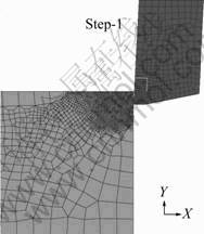
Fig.1 Orthogonal cutting model with tool flank wear
The boundary condition was that constraints in horizontal and vertical directions were applied to the bottom of workpiece. Cutting tool was set as rigid, while workpiece was set as plastic. Shear friction coefficient was set as 0.3, which was a suitable value in high speed cutting of aluminum. The initial temperature was 20 ��. The material properties of the tool and workpiece and the cutting conditions used in FEM simulations are listed in Tables 1 and 2.
Table 1 Material properties of tool and workpiece
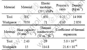
Table 2 Cutting conditions
Based on the effective cutting chip area per rotate, the curved chip was converted into uniform chip, just like plane cutting. And the equivalent chip thickness was calculated out as 0.1 mm according to the feed per tooth value (here the feed per tooth value is 0.15 mm), according to a method listed in Ref.[12].
3 Results and analysis
3.1 Chip formation and shear angle
Traditional theoretical analysis shows that, from the formula below, the deform factor �� can be calculated out.
![]() (1)
(1)
where ach is chip thickness, ac is un-deformed chip thickness.
Then from the formula below, the shear angle �� can be calculated out as
![]() (2)
(2)
where ��0 is the rake angle.
In this study, chip shapes obtained from simulations with different tool flank wear values are compared. From the simulation results, it can be seen that, when a cutting tool gets worn, the tool-chip contact length and the curve radius of the continuous chip do not change in general. The thickness of chip keeps at the same value too, which is kept at about 0.14 mm in this simulation here. As the chip thickness ach is kept at about 0.14 mm, and the un-deformed chip thickness ac is 0.1 mm, so the deform factor �� can be calculated as 1.4 here from Eqn.(1). This means that the deform factor does not change with the degree of flank wear.
As the rake angle �� is 3? here, so the shear angle �� can be calculated out to be about 36.54? from Eqn.(2). Meanwhile, the average shear angle in the steady state from FEM simulations is about 35?, which can be seen from Fig.2 (where the sign bVB means the flank wear width of the flank wear land in the central portion of the active cutting edge). These two values are very close. So, the simulation value of shear angle agrees well with the theoretical analysis value.

Fig.2 Shear angle graph of different flank wear length in simulations
3.2 Influences on stress, strain and strain rate
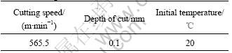
The simulation results show that the degree of flank wear has no influence on the effective stress, and does not affect the strain and strain rate much. Fig.3 shows a graph that shows stress, strain and strain rate may vary with cutting time at different flank wear values. From this graph, it can be seen that, during the steady cutting stage, all effective stress values keep around 655 MPa. And the values of strain maintain between 1.8 and 2.0, which is increased only about 10% when the tool gets worn. The strain rate keeps also between 3.5��105 s-1 and 4.0��105 s-1.
3.3 Influences on variation rules of cutting force
3.3.1 Theoretical analysis of cutting force
From the previous researches[2, 8], we know that there have cutting force relationships as
Fc=Fcs+Fcw (3)
Ft=Fts+Ftw (4)
where Fc is the total cutting force component, Fcs is the cutting force component required for chip formation, Fcw is the wearland force component in the cutting direction, Ft is the total thrust force component, Fts is the thrust force component which is parallel to the shear plane, Ftw is the wearland force component in the thrust direction. The relationship is also revealed in Fig.4. From above the formulae above, both force in cutting and thrust directions will increase when tool flank wear increases. Correct FEM simulation results should also follow this tendency.
Fig.3 Stress, strain and strain rate variation graph with time in different flank wear values: (a) Stress; (b) Strain; (c) Strain rate
3.3.2 FEM analysis of cutting force
There is a slight increase of the horizontal cutting force with the increase of tool flank wear, which can be seen from Fig.5 (a). The increasing amplitude of average force value in horizontal direction is about 5 N (from 90 N to 95 N), although the maximum peak value gets 100 N. And as can be seen from Fig.5(b), when a sharp tool gets worn, the vertical force has a typical change����a shocking phenomenon happens. Our simulation results shows that, for a worn tool, vertical load gets a peak value of 42 N when the cutting tool just cuts into the workpiece a little; but an ideal absolute sharp tool keeps only an average value of 7 N. This phenomenon is very typical for the flank worn tool tip, because another simulation also made by us shows that a rounded tool tip without flank wear only increases the average value a little, but don��t have this typical shocking phenomenon.
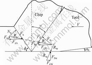
Fig.4 Orthogonal cutting forces model considering tool flank wear effect
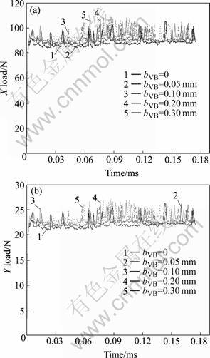
Fig.5 Force load graph with different flank wear length in simulation: (a) X-load; (b) Y-load
Another experiment also pointed out the increase of thrust force with the increase of flank wear length by LIANG[9].
Let FH means the X load, FV means the Y load, so their composite force can be got from the formula:
![]() (5)
(5)
When a sharp tool cuts at first, X load is near 90 N, Y load is near 35 N, and the composite force is just 96.6 N. When tool gets worn, X load is near 95 N, Y load is near 45 N, and the composite force is just 105.1 N. The composite force increases up to at least 8% when cutting tool gets worn.
As can been seen from Fig.6, the position of tool relative to workpiece is shown here just when the thrust force gets the maximum value. This is just the time when the tool cuts into the workpiece in a very short distance and the chip has just formed a little. This phenomenon is very special. It is more important for high speed mill machining rather than turn machining, because milling cutter flutes cut into workpiece frequently in a very short time. And this phenomenon can be set as a recognition method of tool flank wear monitoring in high speed mill machining.
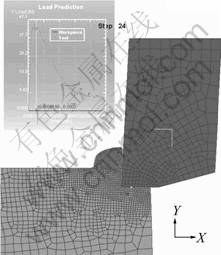
Fig.6 Relative position of tool with largest thrust force
The normal pressure distribution affected by flank wear can be seen in Fig.7. The effective stress named in the software DEFORM is in fact the residual stress. It can be seen that little influence on the effective stress produces in the whole field of workpiece, but the normal pressure distribution around the interface of tool and workpiece changes a little. There exists normal pressure force distributed around the flank wear area.
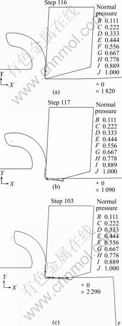
Fig.7 Normal pressure comparison for different tools (tool flank wear value bVB=0, 0.1, 0.2 mm)
3.3.3 Some verifying experiment data of cutting forces
In order to get the correct information in cutting aluminum alloy 7050, a full immersed slot milling experiment was made by us. Fig.8 shows the draft of slot mill cutting experiment equipment, and Fig.9 shows the photo of experiment equipment. The workpiece is a thin plate with a thickness of 3 mm, the material of which is aluminum alloy 7050-T7451. The cutting tool is a two flutes carbide cylindrical cutter with a diameter of 20 mm. And the rake angle is 3?, the clearance angle is 15?. The type of machine tool is Deckel Maho DMU-70V five axes HMC. A force measurement of Kistler 9257 was used.
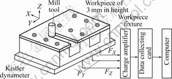
Fig.8 Orthogonal high speed milling force measuring experiment

Fig.9 Photo of force measuring equipment
Fig.10 shows the cutting force measuring values along with cutting time measured in channel 1 and channel 2 (in X and Y direction separately, i.e. feed direction and normal direction). The time field is only chosen for 10 ms. The reason for containing plus and minus force values is that there is a half circle cutting just in one cutting for a single cutting tooth step. From it, we can get one field of cutting forces. When cutting with a sharp tool at first, the maximum value in one channel is 350 N, in another channel is 400 N. Then after the cutting tool gets worn to some degree, the maximum value in one channel is 370 N, in another channel is 420 N. So, it shows cutting forces increase in some degree when the cutting tool gets worn. Cutting forces measured in these two channels increase by about 5% to 6%.
As is listed in front of this paper, the composition of forces in FEM simulation is near 110 N, which just means the magnitude of force in cutting a workpiece of one millimeter thick. Since in this experiment the workpiece plate thickness is 3 mm, the force above should be amplified with the thickness of 3 mm, so the result force is about 330 N. There still have some small gaps between the simulation values and experimental ones, which may be shortened by the exactness in measuring the degree of tool flank wear, and may also be shortened by the accuracy limit in force measuring. Comparing simulation values before, the difference between simulation values and experiment values is rather small considering difficulties in measuring the degree of tool flank wear. It means that our FEM simulations are basically credible.
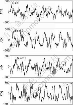
Fig.10 Experimental data of cutting force signal: (a), (b) Before obvious tool flank wear happening; (c), (d) After tool flank gets worn to some degree
The same conclusion was also drawn by LIANG[9]. In his study, an aluminum workpiece was cut by a fresh tool and the worn tools of 0.2, 0.4 and 0.7 mm. From his results, it is obvious that cutting forces increase with the length of tool flank wear, and at the same time the amplitude of vibration increases too.
3.4 Influences on the cutting temperature
As can be seen from Fig.11, with the increase of tool flank wear value (from 0 to 0.2 mm), the maximum cutting temperature also increases up in the contact area between tool and chip. But when the tool flank wear value still increases up to 0.3 mm, this increasing tendency of temperature with flank wear becomes not very obvious. This variation can be explained by the increase of a thermal conduction increasing effect. The contact area between cutting tool and workpiece is also increased when tool flank area gets increased. Therefore the increased thermal conduction limits the increment of temperature. This idea agrees with some conclusions in the previous researches[13-14]. And the temperature difference led by various tool flank wear keeps within an amplitude of 10 ��. It means that, in the procedure of high speed cutting, the heat produced by friction between tool flank and machined surface occupies only a very small part in the whole quantity of heat.
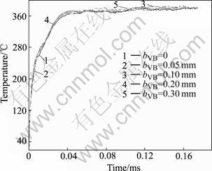
Fig.11 Temperature��time curves under different flank wear lengths
As shown in Figs.12 and 13, the sharp tool and flank wear tool has some influences on the temperature distributions of workpiece and tool. In the steady stage, the maximum cutting temperature at tool-chip interface has an increase of about 5 �� (i.e. from 375 �� to 380 ��), and temperature in the area just below the whole machined surface also increases. Yet for different tool flank wear values, such as 0.1 mm and 0.2 mm, the difference is rather small.
As can be seen from Fig.13, the distance between the maximum temperature point and the cutting tool tip point becomes short after that cutting tool becomes worn. And the temperatures near the tool tip change a little to some degree. For the limitation of equipments, only force test was made by the authors so far, the temperature experiment will be carried out in the next stage.
4 Conclusions
1) The flank wear have no influences on the stress, and almost does not affect the strain rate. And also the tool flank wear does not affect the basic cutting quanti- ties such as the shear angle, chip thickness and curling-radius curvature of continuous chip. But it affects the horizontal load force to some degree, and affects the thrust force more sensitively, which can be taken as a method to recognize the tool flank wear in on-line monitoring during the milling process.
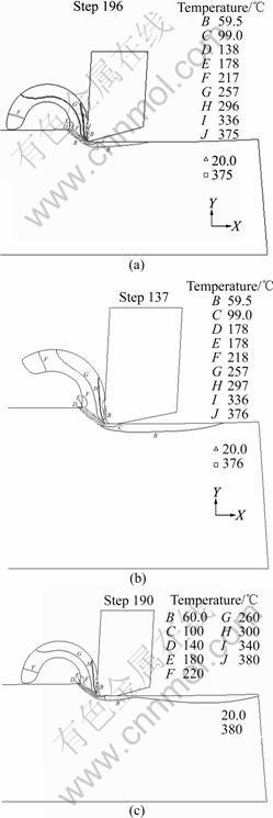
Fig.12 Effect of tool flank wear on temperature distribution at workpiece: (a) VB=0; (b) VB=0.1 mm; (c) VB=0.2 mm
2) The cutting temperature rises with the wear degree of sharp cutting tool, but gets stabilized soon. Tool flank wear will also increase the temperature underneath the cutting tool.
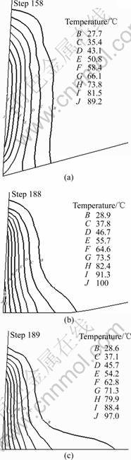
Fig.13 Effect of tool flank wear on temperature distribution at tool tip: (a) VB=0; (b) VB=0.1 mm; (c) VB=0.2 mm
3) Such conclusions agree well with the experimental measurements in public literatures and the experiment carried out by the authors. The result can also be used as an on-line method to detect the tool wear in the metal cutting process.
References
[1] OLBERTS D R. A study of the effects tool flank wear on tool chip interface temperature [J]. Trans ASME, Journal of Engineering for Industry, 1959, 81: 152-158.
[2] MCADAMS H T. Rosenthal paul, forces on a worn cutting tool [J]. Trans ASME, Journal of Engineering for Industry, 1961, 83: 505-512.
[3] CHANDRASEKARAN H, NAGARAJAN R. Influence of flank wear on the stresses in a cutting tool [J]. Trans ASME, Journal of Engineering for Industry, 1977, 99: 566-577.
[4] CHEN N N S, PUN W K. Stresses at the cutting tool wear land [J]. International Journal of Machine Tools and Manufacturing, 1988, 28: 79-92.
[5] WANG J Y, LIU C R. The effect of tool flank wear on the heat transfer, thermal damage and cutting mechanics in finish hard turning [J]. CIRP Annals, 1999, 48: 53-58.
[6] SMITHEY D W, KAPOOR S G., DEVOR R E. A worn tool force model for three-dimensional cutting operations [J]. International Journal of Machine Tools and Manufacture, 2000, 40: 1929-1950.
[7] SIKDAR Sumit Kanti, CHEN Mingyuan. Relationship between tool flank wear area and component forces in single point turning [J]. Journal of Materials Processing Technology, 2002, 128: 210-215.
[8] WANG J, HUANG C Z, SONG W G. The effect of tool flank wear on the orthogonal cutting process and its practical implications [J]. Journal of Materials Processing Technology, 2003, 142: 338-346.
[9] LIANG S Y, KWON Y K, CHIOU R Y. Modelling the effect of flank wear on machining thrust stability [J]. International of Journal Advanced Manufacture Technology, 2004, 23: 857-864.
[10] HUANG Yong, LIANG Steven Y. Modeling of cutting forces under hard turning conditions considering tool wear effect [J]. Journal of Manufacturing Science and Engineering, 2005, 127: 262-270.
[11] XIE L J, SCHMIDTA J, SCHMIDTA C, BIESINGERB F. 2D FEM estimate of tool wear in turning operation [J]. Wear, 2005, 258(10): 1479-1490.
[12] ?ZEL T, ALTAN T. Process simulation using finite element method��prediction of cutting forces [J]. Tool stresses and temperatures in high speed flat end milling [J]. International Journal of Machine Tools and Manufacture, 2000, 40: 713-738.
[13] LIN Zone-Ching, CHANG Fu-Siang, LIN Yang-Tai. The effect of tool flank wear on the temperature distribution of a machined workpiece [J]. Journal of the Chinese Institute of Engineers, 1987, 10(4): 353-362. (in Chinese)
[14] YOUNG H T. Cutting temperature responses to flank wear [J]. Wear, 1996, 201: 117-120.
(Edited by LI Xiang-qun)
Foundation item: Project(50435020) supported by the National Natural Science Foundation of China
Corresponding author: YUAN Ping; Tel: +86-571-87951061; E-mail: pingxp@zj.com
