

J. Cent. South Univ. (2018) 25: 855-865
DOI: https://doi.org/10.1007/s11771-018-3789-5

Bionic structure of shark��s gill jet orifice based on artificial muscle
DU Ye(��Ұ)1, 2, ZHAO Gang(�Ը�)1, SUN Zhuang-zhi(��׳־)1, GU Yun-qing(������)3
1. College of Mechanical and Electrical Engineering, Harbin Engineering University, Harbin 150001, China;
2. Harbin University of Science and Technology Rongcheng Campus, Rongcheng 264300, China;
3. College of Mechanical Engineering, Zhejiang University of Technology, Hangzhou 310014, China
 Central South University Press and Springer-Verlag GmbH Germany, part of Springer Nature 2018
Abstract:
Based on the biological prototype characteristics of shark��s gill jet orifice, the flexible driving characteristics of ionic exchange polymer metal composites (IPMC) artificial muscle materials and the use of sleeve flexible connector, the IPMC linear driving unit simulation model is built and the IPMC material-driving dynamic control structure of bionic gill unit is developed. Meanwhile, through the stress analysis of bionic gill plate and the motion simulation of bionic gill unit, it is verified that various dynamic control and active control of the jet orifice under the condition of different mainstream field velocities will be taken by using IPMC material-driving. Moreover, the large-deflection deformation of bionic gill plate under dynamic pressure and the comparative analysis with that of a rigid gill plate is studied, leading to the achievement of approximate revised modifier from real value to theoretical value of the displacement control of IPMC.
Key words:
Cite this article as:
DU Ye, ZHAO Gang, SUN Zhuang-zhi, GU Yun-qing. Bionic structure of shark��s gill jet orifice based on artificial muscle [J]. Journal of Central South University, 2018, 25(4): 855�C865.
DOI:https://dx.doi.org/https://doi.org/10.1007/s11771-018-3789-51 Introduction
Jet drag reduction of moving objects is realized by injecting fluid at low speed to the mainstream field in order to change the wall boundary condition and surrounding flow field structure of moving objects and achieve the goal of reducing the resistance [1, 2], which has been developed and widely applied in the development of the hypersonic aircraft. VENUKUMAR et al [3], MEYER et al [4] and BUSHNELL [5] have found that the resistance can be reduced by 30%�C45% through the change of the jet orifice pressure value in the reverse flow drag reduction. MILES et al [6] and MENART et al [7] applied ionization to the head or outside surface of a high speed aircraft, resulting in a virtual fairing to reduce the motion resistance. However, for surface vessels and underwater vehicles navigating at low speed, their friction resistance is the largest energy-consuming factor, even reaching 50%�C70% of total motion resistance [8]. At present, little research has been done in the development and application of the jet drag reduction technology in low-speed vessels or vehicles.
In recent years, the bionic drag reduction technology has gradually become a hot research project in the field of low-speed navigation. Living things have long been evolving through variation and natural selection for the continuation of their lives. In a sense, it is inevitable that the simulation of physical characteristics for a living thing and their application to the engineering practice will help get twice the result with half the effort. For example, some drag reduction technologies such as groove design, indentation and convex hull have been developed on the basis of bionic non-smooth surfaces of insects [9�C11], and those on the curved surface and elasticity of bionic dolphin skin are also studied [12].
The shark, as ancient species, has excellent water movement ability after a long natural selection. The non-smooth scaly surface of a shark is characterized by its extraordinary drag reduction, which has been applied to the development of swimwear and the surface of the aircraft (groove sticker), and the efficient propulsion mode of shark��s tail has been used in underwater robot driving. Moreover, the pressure drag is also greatly reduced due to the shark��s streamline shape [13, 14]. In recent years, the author��s team has been focusing on the respiratory jet function of shark gill��and put forward the method of drag reduction by imitating the jet surface of shark gill [15�C17]. Furthermore��the huge physical characteristics driven by the jet function and the simple gill split structure which is easily imitated and processed are favorable conditions for its application in the bionic jet drag reduction technology in the field of ships and other fields.
Although some achievements have been made in the study of the biomimetic jet drag reduction technology on shark��s gill, they are mostly under the condition of mainstream constant velocity and with the jet orifice in rigid regular shapes (round, rectangular, etc.) that cannot be adjusted in the process of movement [14, 18�C21], which cannot reflect the real change taking place with the change of flow field when shark��s gills work in actual movement, nor can they be used in the practical operation of aircraft. The comparative study on fixed jet orifice shapes made by WESTON et al [22] and BARBER et al [23] also shows that the different shapes of jet orifice exert different effects on the flow field and the orifice surface pressures [24, 25]. Therefore, based on the systematical study and analysis of biological prototype characteristics of the shark��s gill jet orifice, the artificial muscle IPMC material is introduced to the design of the bionic jet orifice in this work. It can be realized with the flexible driving of the bionic biological muscles, because the shape of bionic shark��s gill jet orifice changes with the mainstream velocity, giving rise to its active control function.
2 Biological prototype of shark��s gills
In this study, Mustelus manazo Bleeker sharks, which can be found in large numbers in China��s Bohai coastal waters, are selected as the research objects and both observation experiment and biological anatomy of shark��s gills are carried out. This research mainly focuses on the physical features, breathing jet action principle, and the relationship between musculoskeletal structure of the gill and its movement, to obtain a model of the biological characteristics for shark��s gills.
2.1 Attainment of external features of sharks gills
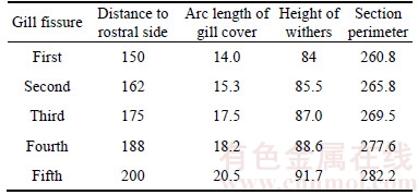
As shown in Figure 1, the shark��s gill jet orifice is in the shape of a rectangle, and there are totally five gill fissures with smooth and round junctions. When gill fissures are open, gill filaments can be found on both sides, and most of them feature flexible tissues. Quantitative analyses are made on the location and size of each gill fissure, and the results are shown in Table 1. It is found that the cross-sectional dimension of the head increases with gradually increasing distance to the snout, but the change in length is so small that the five gill fissures can be considered substantially identical in size and evenly distributed. In addition, it is also found through observation and anatomical experiments that the internal and external structures of each jet orifice are basically the same. Therefore, in the follow-up study, only the fifth, or the biggest, gill fissure is selected.
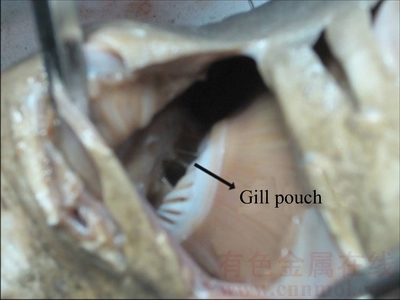
Figure 1 Gills fissures of shark
2.2 Analysis of orifice structure and jet motion
Through observation and anatomical analysis,it is found that the regulation of jet flow pattern for the shark is realized through the relative motion of the structures in the jet orifice. When the shark��s oral cavity is full of water, muscle in the gill arch contracts to enlarge the volume of the gill sacs on both sides, and the water flows into the gill sacs, completing the respiration here. Later, under the effect of contraction with the gill septum constrictor in the gill and two constrictors in the back and abdomen, the gill sacs is compressed, and water is forced to flow out of the gill fissures to complete the jet. A simplified model of the jet prototype for the shark��s gills has been obtained by the author��s team. We also found that the angle between gill fissure and fish spine axis is generally not more than 60�� when most sharks are swimming.
Table 1 Location and size dimensions of gill fissures (Unit: m)
The further analysis shows that the regulating function of jet angle is realized by changing the swing angle of between gills, and the adjustment of jet orifice size is realized by changing the position of two gill plates in a jet orifice, thereby affecting the state of the jet. Meanwhile, it is also proved that the jet velocity is affected by the water performance of the gill sac and the cross-sectional area of the flow at the outlet. In this work, it is assumed that the supply system can provide a constant flow of jet fluid, so the change of the jet velocity is mainly related to the size of the cross-sectional area of the flow for the outlet of the jet orifice, which is believed to be a biological prototype support for the idea that jet velocity can be changed by adjusting the effective surface area of the gill jet orifice.
2.3 Composition and motion analysis of gills�� musculoskeletal structure
From the principle of shark��s breathing jet and its musculoskeletal structure, it is known that the movement of shark��s gills is realized through the opening and closing of the gill arch which is controlled by the muscle group in the gills, and the rotatable gill arch structure is the key to the realization of the state adjustment of jet flow. In addition, the motion of the gills arch is also affected by the muscle group between gills on the external gill cartilage to a certain extent. The gill arch skeleton is connected with the head bone through the solid ligaments and other connective tissues,so that an overturning movement less than 60��angle is achieved, and the movement is relatively stable. In addition to the autonomous movement of the gill structure,the jet state is also influenced by the deformation of the gill plate under the action of the flow field. It is found through observation that the movement of the shark��s gills is basically stable due to the simultaneous opening and closing of the five gill fissures, thus the design concept of bionic gill unit is proposed in this work.
3 Overall design and simulation of bionic gill
3.1 Design scheme
Based on the flexible adjustment feature for the angle and the shape of jet orifice in the jet process, this work studies the flexible driving process of the shark��s gill jet simulated by using the IMPC artificial muscle material which is greatly similar in performance to biological muscles, as a result, the angle and size of the bionic gill jet orifice will realize the dynamic adjustment with the changing flow field. Figure 2 shows the whole- cutaway view of the structure of the bionic gill unit.
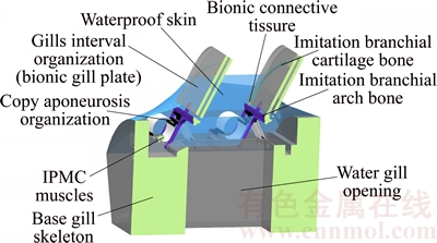
Figure 2 Cutaway view of bionic gill unit
1) Drive unit. Compared to the rigid driving mode for traditional mechanical structure of the bionic gill, the flexible IPMC material can help realizing the active control of the bionic structure. IPMC drive has many advantages, for instance, small vibration, fast response, low energy consumption, bigger thrust-weight ratio, easy coordinated control, simple structure and easy underwater sealing. In addition, muscle structures in different shapes can be prepared according to the needs. The actuating mechanism of IPMC is that under the action of the electric field, hydrated cations in the electrified IPMC film are forced to move to one side of the muscle film, resulting in the expansion due to the increase of the water molecules, thereby generating bending deformation. The former IPMC bionic linear driving unit developed by the author��s team is used in the driving structure, as shown in Figure 3.
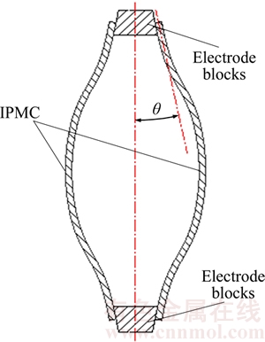
Figure 3 Principle diagram of bionic linear drive unit
The design of the drive unit is to mimic the movement form of the shark muscle. The two symmetrical muscle strips on both sides help turning the bending deformation of IPMC material into a linear driving unit with a capability of linear output, producing an axial linear driving force and greatly enhancing the size and stability of the force output. The one-piece IPMC is replaced by a three-piece structure in the design so that the problem of anti-torque existing at both ends of the joint when material bending deformation occurs can be solved. By applying voltages in different directions to the adjacent end, the whole muscle can produce the same deformation effect, which can improve the performance of the force output. At the same time, the defect of smaller output force of IPMC material is also followed, therefore, the problem of insufficient output force in practical applications is better solved with the superposition combination method.
2) Selection of bionic connecting parts. The connection of all parts for the shark is accomplished through connective tissues, and the bones and muscles are connected by aponeurosis or tendon, with the result that the movement is transferred and adapts to the change of direction in the process of transference without affecting the output performance of the muscular contracting force. In this design, the gill arch bones and muscle strips are connected by aponeurosis made of high strength polyethylene fiber cloth, and gill cartilage and gill arch are connected by connectors made of nylon fiber (polyester fiber) good at breaking strength and elasticity.
3) Design of skin and soft tissue. The soft tissues of the bionic gill unit include the skin and the gill plate. The PDMS (polydimethylsiloxane, poly two methyl silicone) material for the skin is a simple and flexible material and can reduce energy consumption by 40%�C50%. Meanwhile, the rubber sheets flexible materials are selected for the gill plate to complete the simulation of its flexible deformation.
4) Design of skeleton structure. The skeleton system of the bionic gill unit is simulated after the main bone structure of the shark��s gill. The three major parts-bionic basibranchial bones, gill arch bones and external gill cartilage are used. The designed structure can be manufactured with the 3D technology, because it is close to that of the shark in structure.
3.2 Building of structural model
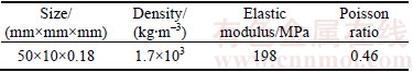
In this design, the IPMC linear drive unit is made of a long rectangular thin material with a length-to-width ratio of 4, and it is simple in shape equivalent to a flexible beam structural model. But in order to avoid the shear locking phenomenon of Timoshenko beam connection in the thin beam, the flexible connection mode based on the bushing is chosen in this design. The mechanical properties of IPMC can be found in Table 2.
Table 2 Mechanical properties of IPMC material
As shown in Figure 4, the fluid field domain size is 100 mm��200 mm��100 mm, far greater than the space volume of the gill plate, so the fluid domain��s wall cannot be considered to affect the flow field, which can be used to simulate the movement of the gill plate in vast waters. A wall distance of more than 40 mm is arranged in the water inlet end to allow water to flow fully, ensuring the stability of the flow.
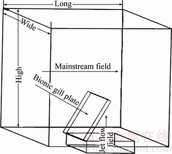
Figure 4 Flow model for solid
In this work, the velocity of the mainstream field is selected based on the low-speed movement of the shark and the prototype performance, and the speed of the AUV is consulted (maximum speed 1.5 m/s) within the flow velocity range of 0.5�C1.3 m/s (step of 0.1 m/s) selected to simulate that of the mainstream field, and jet velocity range of 0.002�C0.018 m/s, and the swing range of the bionic gill 20��C60�� with 5�� as a changing unit.
In terms of the design requirements for movement simulation in vast waters, the standard k�C�� turbulence model most widely used in engineering is adopted in this work. The turbulent motion equation can be expressed as the turbulent kinetic energy and the turbulent consumption rate:
 (1)
(1)

 (2)
(2)
where ��tij is the Reynolds stress of Eddy viscosity model, Sij is resilience-speed tensor, and fk is item-wall.
4 Simulation analysis of bionic gill unit model
4.1 Simulation analysis of bionic gill plate stress
From the drag reduction theory of bionic jet surface, we know when there is side low speed jet occurring in the mainstream field with a relatively higher speed, the viscous resistance of the object wall is reduced. Generally, the lateral jet velocity is very different from the mainstream field velocity, so the impact of the jet flow field on the gill plate can be neglected, and simulation can be done with computational fluid dynamics (CFD) numerical simulating method. The complex fluid environment in water was not taken into consideration when using conventional Newtonian particle system dynamics analysis and energy analysis methods. However, a calculation method of fluid-solid coupling is used in this work.
Based on the design requirements, when jet angle adjustment is completed by bionic gill plate with gill arch skeleton swinging, no jets are produced. So in this process, the bionic gill plate is only subjected to dynamic pressure from the mainstream field. But when the jet angle is fixed, a lateral dynamic pressure on the bionic gill plate is generated in the jet process. Simulation calculation for the two kinds of stress leads to the results shown in Figure 5. As is shown, the minimum mainstream field velocity is 0.5 m/s, the maximum jet flow field velocity is 0.019 m/s and the angle between the gill plate and the fish ridge line is 20��. In such a case, the dynamic pressure of the mainstream field is the smallest and the dynamic pressure of the jet flow field is the largest.
It can be seen from the simulation results of Figure 5 that the stress state of the gill plate in the two flow fields is basically consistent, which shows that the lateral pressure provided by the jet flow field is very small. In follow-up studies on jet angle adjustment by bionic gill spacing swing, the main resistance is considered to be the dynamic pressure of the mainstream field on the gill plate.Here, the arithmetic selection of different mainstream field velocities and swinging angles results in a series of discrete points, and the use of the three- interpolation method based on triangle leads to how the stresses of the gill plate change as shown in Figure 6. It can be seen that the stress on the gill plate increases with the increase of the mainstream velocity and the angle between the gill plate and the ridge line. Through the above stress analysis, it is verified that the application of IPMC artificial muscle material in the connecting part of the bionic gill jet model meets the requirements of stress transmission.
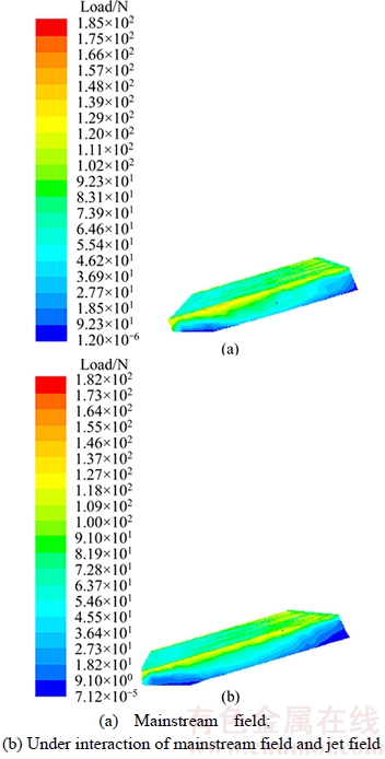
Figure 5 Pressure cloud picture of bionic gill plate in different flow field status:

Figure 6 Fitting surface chart of dynamic pressure, mainstream field velocities and swinging angles
4.2 Establishment and analysis of bionic gill unit movement simulation model
Based on the structural model of the bionic gill unit, the gill spacer swing system model under the simulation environment is established. In the model,the IPMC driver modules located on both the front and rear sides of the gill interval are respectively connected with the flexible bionic aponeurosis which is attached to the gill arch skeleton.The connection of the gill arch skeleton to the gill basal bone is realized by a rotating pair. Bionic gill plate structure above gill arch and the gill arch skeleton are connected and fixed by bionic connective tissues.
Flow regulation is achieved in the relative movement of the two bionic gill spacers, and the adjustment of the jet angle is accomplished by controlling the expansion and contraction of the IPMC driving unit to adjust the swing angle of the bionic gill spacer I. After the jet angle is determined, due to the movement of the gill plate,the position relationship between the two gill plates is changed, which leads to the change of the jet velocity at a certain flow rate. When disconnecting the IPMC driving voltage in the forward swing direction, the gill plate helps achieving rapid opening and closing of the jet orifice under the action of the water pressure and the reverse IPMC drive unit.
4.2.1 Simulation of process of opening and closing of jet orifice
The movement of two gill spacers when opening is shown in Figure 7. If its movement corresponds to the flow regulation, the direction of the jet is determined by the position of the swing angle of the gill spacer I. When the jet angle is determined, the movement of the gill spacer II can help achieving the relative change of position. So when the jet flow is constant, the jet velocity can be regulated by the size of the jet orifice.
The analysis of the simulation results of gill spacer I shows the relationship between the amount of displacement of the IPMC driving unit (y) and the jet angle (x), as shown in formula (3). The analysis of the simulation results of the movement of gill spacer II shows the relative position changes of the two gill spacers corresponding to the jet velocities at a fixed flow rate. If the swing angle of gill spacer I is set as ��1, the swing angle of gill spacer II is set as ��2, their relative angle is set as ��=��1�C��2, and the position of 30 mm on the gill plate is taken as the measurement point, then the relationship between the distance and the relative angle is shown in formula (4).
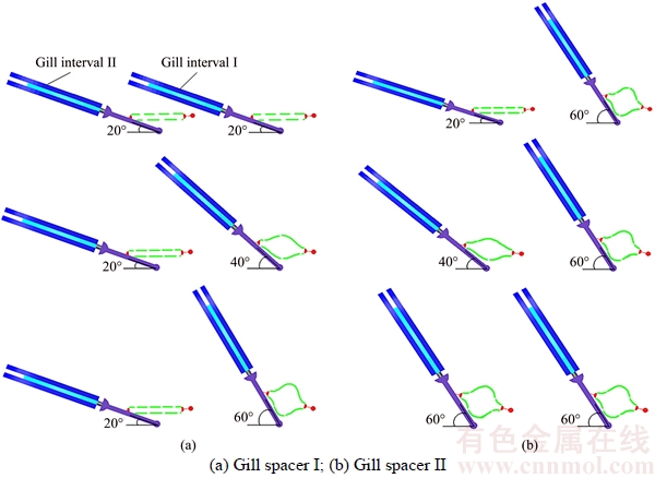
Figure 7 Gill spacer motion diagram:
y=0.0025x2+0.7649x+49.968 (3)
y=0.001x2+0.0803x�C2.0073 (4)
When the device stops working on the flow pattern, the jet orifice needs to be closed. Since the closing movement and opening movement are similar, the latter is not described here.
In this part, the simulation analysis of the opening and closing of the jet orifice swing system helps to get the control law of IPMC driving unit, jet angle and jet velocity. The determination of the movement relationship shows the actual motion control and the realization of the function.
4.2.2 Analysis of large deflection deformation of bionic gill plate
The stress on the gill plate is characterized by the fluid-solid coupling, and the fluid pressure can be directly guided into the fluid-solid coupling surface. Again an analysis is made on the deflection change of the gill plate with different swing angles and the mainstream field velocities. The simulation results show that the deformation of the gill plate is the most obvious when the mainstream field velocity is 1.3 m/s. The deformation cloud images at different swing angles are shown in Figure 8.
A fixed mainstream field velocity with the gill plate angle of 60�� from closing to opening can be seen from the deformation cloud, and the deformation increases gradually and the maximum deflection occurs at the midpoint on the free end. The trend of deformation is that depression occurs in the middle part, and the whole piece becomes an arc structure. The deformation of the bionic gill plate is actually generated by dynamic pressure, so deformation deflection is a function of the swing angle and the mainstream field velocity.
In consideration of the two variables which can influence deformation, we select the same swing angle and mainstream field velocity in the stress analysis, and draw a deflection diagram with different swing angles and the mainstream field velocities, as shown in Figure 9.
We can see from the change chart that, in a certain mainstream field, the deflection increases with the increase of the swing angle of the bionic
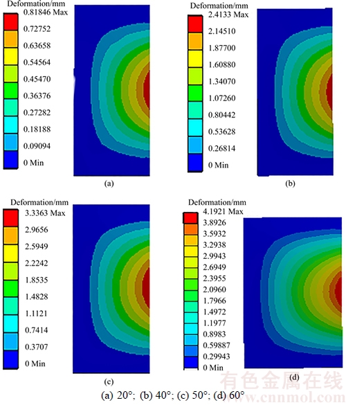
Figure 8 Deformation of bionic gill plate at mianstream field velocity of 1.3 mm/s at diflerent swing angles:
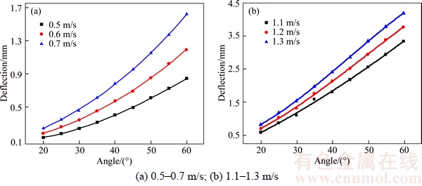
Figure 9 Deflection variation at different swing angles in different mainstream fields:
gill plate. And with the increase of the mainstream field velocity, the deflection also increases gradually. That is, the deflection is the binary function of the swing angle and the mainstream field velocity.
In this work, a flexible rubber material is used to simulate the movement of the shark gill in water. The flexible deformation can adjust vortex forms of the near field and enhance the hydrodynamic performance. In addition, because of the passive deformation of rubber material in water, it is known from the principle of flexible drag reduction that its deformation can reduce the pulsating resistance in turbulent situation. Therefore, the flexible deformation of the bionic gill plate in water causes less motion and jet energy loss.
4.2.3 Analysis of influence of flexible gill plate on flow pattern of jet
The functional mapping relationship between the motion of the IPMC driving unit and the angle of the jet is obtained by the simulation analysis of the bionic gill spacer swing device. However, under the influence of the flexible deformation of the gill plate, the relationship between the jet angle and the movement of the rigid body system will have a certain deviation called end angle. Because of the existence of the end angle, there is a certain gap between the angular position of the gill plate and the theoretical value. When jet is practiced, the jet angle is influenced by the flexible deformation of the gill plate, causing jet to flow in the direction of the tangent of free surface of the gill plate, which leads to deviation from the results of analysis of rigid body systems.
Based on the above deformation simulation analysis of the gill plate, we can obtain the change values of the end angle at different mainstream field velocities and swing angles. It can be known from Table 3 that the maximum value of the end angle of the gill plate is 5.98��, the minimum value is 0.19��, and the maximum end angle is sufficient to affect the adjustment of the jet angle. Therefore, we need to change the driving control of IPMC material to further improve the design scheme to meet the requirements for actual application.
Based on the analysis in Section 4.2.1, it can be seen that when the bionic gill plate is treated as a rigid body, the relationship between the displacement change of IPMC and the swing angle is a fixed function law which is not influenced by the factors in the mainstream field. However, actually the bionic gill plate is a flexible thin plate which can produce deformation under the pressure of the mainstream field, and the deflection increases with the increase of the mainstream field. From Figure 10, it can be seen that with the increase of the flow velocity, the displacement of the IPMC driving unit is required to be increased to form a predetermined jet angle. And the deviation should be taken into account in the actual motion control of the bionic gill.
It can be found from the analysis of the variation trend of the curves in Figure 10 that the deviation is related to the variation of the flow velocity, that is, there is a mapping relationship between the actual movement of the IPMC driving unit and the jet angle. Because of the smooth curves, the functional mapping relations can be expressed by using the polynomial fitting method with higher order. By fitting the polynomial coefficients of the fitting function, the coefficient of variation of the theoretical displacement is found to remain constant at 0.23. The two coefficients and the constant coefficient show a regular change and are in line with the selected arithmetic velocity change, and the difference between the actual value and the theoretical value can be calculated, with corrected expression as:
 (5)
(5)
where ��V is the difference between the current mainstream field, the minimum flow velocity and ��S is theoretical displacement variation. Therefore, in the calculation of the actual jet angle value, it can be approximately expressed by theoretical value subtract ��.
Table 3 Variables of end angle at different swing angles and mainstream velocities
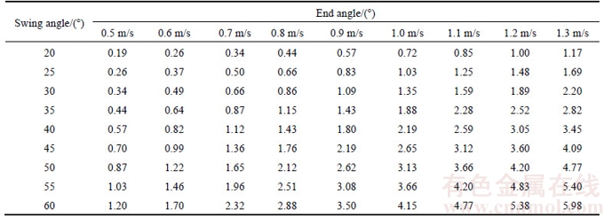
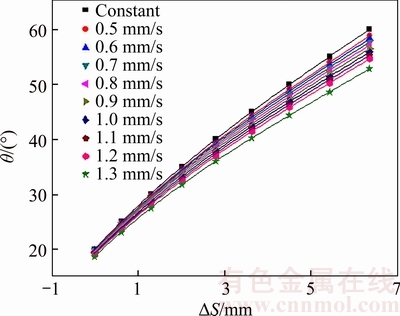
Figure 10 Relationship between IPMC displacement variation and jet angle under different mainstream conditions
5 Conclusions
1) Based on the flexible adjustment of the angle and shape of the jet orifice in the process of shark��s gill jet, the IPMC artificial muscle material is used to simulate the driving of the muscle bone of the shark��s gill during its jet, resulting in the proposition of the bionic gill unit. The drive unit turns the bending deformation of the IPMC material into a linear driving unit with linear output power, which greatly enhances the size and stability of the force output. Finally, the active regulation of the angle and shape of the bionic gill jet is realized through the flexible driving of IPMC material.
2) The analysis of the stress on the gill plate shows that the stress on the gill plate increases with the increase of the mainstream field velocity and the angle between the gill plate and the ridge line. The determination of the motion relationship explains that the motion control and function of the designed bionic gill orifice can be realized. The flexible deformation of the bionic gill plate in water also helps to reduce the movement and jet energy.
3) Under the influence of the flexible deformation of the gill plate under stress, the relationship between the jet angle and the movement of the rigid body system has a certain deviation. In this work, the approximate solution to the modified real and theoretical variables of the IPMC displacement control is obtained by comparing the motion laws of the flexible and rigid gill plates.
References
[1] ZHANG Ding-wu, WANG Qiang, HU Hai-yang. Aerodynamic characteristics of sonic injection through diamond-shaped orifices in supersonic flow field [J]. Journal of Aerospace Power, 2012, 27(10): 2378�C2383. (in Chinese)
[2] HUANG Qiao-gao, PAN Guang, HU Hai-bao, LIU Zhan-yi. Investigation about drag reduction characteristic of riblets surface on vehicle model in water tunnel [J]. Journal of Experiments in Fluid Mechanics, 2010, 24(3): 50-53. (in Chinese)
[3] VENUKUMAR B, JAGADEESH G, REDDY K P J. Counterflow drag reduction by supersonic jet for a blunt body in hypersonic flow [J]. Physics of Fluids, 2006, 18(11): 104�C118.
[4] MEYER B, NELSON H F, RIGGINS D W. Hypersonic drag and heat-transfer reduction using a forward-facing jet [J]. Journal of Aircraft, 2001, 38(4): 680�C686.
[5] BUSHNELL D M. Shock wave drag reduction [J]. Annual Review of Fluid Mechanics, 2004, 36: 81�C96.
[6] MILES R B, MACHERET S O, SHNEIDER M N,STEEVES C, MURRAY R C, SMITH T, ZAIDI S H. Plasma-enhanced, hypersonic performance enabled by MHD power extraction [J]. AIAA Paper, 2005, 561: 10�C13.
[7] MENART J, SHANG J, ATZBACH C, MAGOTEAUX S, SLAGEL M, BILHEIMER B. Total drag and lift measurements in a Mach 5 flow affected by a, plasma discharge and a magnetic field [J]. AIAA Paper, 2005, 947: 10�C13.
[8] KOELTZSCH K, DINKELACKER A, GRUNDMANN R. Flow over convergent and divergent wall riblets [J]. Experiments in Fluids, 2002, 33(2): 346�C350.
[9] TIAN Li-mei, REN Lu-quan, LIU Qing-ping, HAN Zhi-wu, JIANG Xiao. The mechanism of drag reduction around bodies of revolution using bionic non-smooth surfaces [J]. Journal of Bionic Engineering, 2007, 4(2): 109�C116.
[10] REN Lu-quan, LI Xiu-juan. Functional characteristics of dragonfly wings and its bionic investigation progress [J]. Science China Technological Sciences, 2013, 56(4): 884�C897.
[11] WANG Bao, WANG Jia-dao, CHEN Da-rong. Drag reduction on hydrophobic transverse grooved surface by underwater gas formed naturally [J]. Acta Physica Sinica, 2014, 63(7): 074702(1�C7). (in Chinese)
[12] BEWLEY T R. A fundamental limit on the balance of power in a transpiration-controlled channel flow [J]. Journal of Fluid Mechanics, 2009, 632(10): 443�C446.
[13] SONG Bao-wei, REN Feng, HU Hai-bao, GUO Yun-he. Drag reduction on micro-structured hydrophobic surfaces due to surface tension effect [J]. Acta Physica Sinica, 2014, 63(5): 054708(1�C9). (in Chinese)
[14] CAI Jin-sheng, LIU Qiu-hong. Numerical investigation of lateral jets in supersonic cross-flows [J]. Acta Aerodynamica Sinica, 2010, 28(5): 553�C558. (in Chinese)
[15] ZHAO Gang, GU Yun-qing, ZHAO Hua-lin, XIA Dong-lai, YAO Jian-jun. Numerical simulation of the drag reduction characteristics of a bionic jet surface aperture coupled with jet speed [J]. Journal of Harbin Engineering University, 2012, 33(8): 1001�C1007. (in Chinese)
[16] ZHAO Gang, ZHAO Hua-lin, SHU Hai-sheng, ZHAO Dan, GU Yun-qing, XIA Dong-lai. Simulation study of bionic jetting direction influence on drag reduction effect [J]. Advances in Natural Science��Nanoscience and Nanotechnology, 2010, 3(2): 17�C26.
[17] ZHAO Gang, GU Yun-qing, XU Guo-yu, XIA Dong-lai, ZHAO Hua-lin, YAO Jian-jun. Experimental study on drag reduction characteristics of bionic jet surface [J]. Journal of Central South University: Science and Technology, 2012, 43(8): 3007�C3012. (in Chinese)
[18] GU Yun-qing, ZHAO G.ang, ZHENG Jin-xing, LI Zhao- yuan, LIU Wen-bo, MUHAMMAD F K. Experimental and mumerical investigation on drag reduction of non-smooth bionic jet surface [J]. Ocean Engineering, 2014, 81: 50�C57.
[19] CHEN Li-wei, WANG Guo-lei, LU Xi-yun. Numerical investigation of a jet from a blunt body opposing a supersonic flow [J]. Journal of Fluid Mechanics, 2011, 684: 85�C110.
[20] JIANG Zong-lin, LIU Yun-feng, HAN Gui-lai, ZHAO Wei. Experimental demonstration of a new concept of drag reduction and thermal protection of hypersonic vehicles [J]. Acta Mechanica Sinica, 2009, 25(3): 417�C419.
[21] GU Yun-qing, ZHAO Gang, ZHENG Jin-xing, WANG Fei, LI Zhao-yuan, LIU Wen-bo, ZHAO Hua-xing. Characteristics of drag reduction on coupling of jet surface main flow field velocity and jet velocity [J]. Journal of Central South University: Science and Technology, 2012, 43(12): 4713�C4721.(in Chinese)
[22] WESTON P R, THAMES F C. Properties of aspect-ratio-4.0 rectangular jets in a subsonic cross-flow [J]. Journal of Aircraft, 1979, 16(10): 701�C707.
[23] BARBER M, SCHETZ J, ROE L. Normal sonic helium injection thorough a wedge shaped orifice into a supersonic flow [J]. Journal of Propulsion and Power, 1997, 13(2): 257�C263.
[24] JIANG Guo-qiang, REN Xiu-wei, LI Wei. Numerical simulation of vorticity dynamics for turbulent jet in cross- flow [J]. Advances Water Science, 2010, 21(3): 307�C314. (in Chinese)
[25] LI Fang, ZHAO Gang, LIU Wei-xin, ZHANG Shu, BI Hong-shi. Numerical simulation and experimental study on drag reduction performance of bionic jet hole shape [J]. Acta Physica Sinica, 2015, 64(3): 034703(1�C8). (in Chinese)
(Edited by FANG Jing-hua)
���ĵ���
�����˹�����ķ��������������ṹ�о�
ժҪ�����Ļ���������������������ԭ����������Ͼۺ���������ϲ��ϣ�IPMC���˹�������ϵ����������ص㣬ʹ�ó����������Ӽ�������IPMCֱ��������Ԫ����ģ�ͣ������IPMC���������ķ�������Ԫ����������״��̬���ƽṹ��ͬʱ��ͨ��������Ʒ��������������������������Ԫ���Ϲ��̵��˶�����ģ�⡢����Ĵ��Ӷȱ��μ����������̬��Ӱ��ȵ�ģ���������֤�˲���IPMC���������ķ�������������ģ���ܹ�ʹ�������ڱ����������������»�ò�ͬ��б�ǡ���ͬ��С����ͬ��״�Ķ�̬���Ƽ��������ơ����⣬����ͨ���о����������ڶ�ѹ�������µĴ��Ӷȱ������⣬�����������������������̬�������жԱȣ������IPMCλ�ƿ�������ʵֵ������ֵ�Ľ�����������
�ؼ��ʣ����������ף�IPMC���������ǽṹ����������Ԫ
Foundation item: Project(51275102) supported by the National Natural Science Foundation of China; Project(HEUCF140713) supported by the Fundamental Research Funds for the Central Universities, China
Received date: 2016-07-20; Accepted date: 2017-03-20
Corresponding author: ZHAO Gang, PhD, Professor; Tel: +86�C631�C7592280, Fax: +86�C631�C7567227; E-mail: zhaoheu@gmail.com; ORCID: 0000-0002-5346-7056
Abstract: Based on the biological prototype characteristics of shark��s gill jet orifice, the flexible driving characteristics of ionic exchange polymer metal composites (IPMC) artificial muscle materials and the use of sleeve flexible connector, the IPMC linear driving unit simulation model is built and the IPMC material-driving dynamic control structure of bionic gill unit is developed. Meanwhile, through the stress analysis of bionic gill plate and the motion simulation of bionic gill unit, it is verified that various dynamic control and active control of the jet orifice under the condition of different mainstream field velocities will be taken by using IPMC material-driving. Moreover, the large-deflection deformation of bionic gill plate under dynamic pressure and the comparative analysis with that of a rigid gill plate is studied, leading to the achievement of approximate revised modifier from real value to theoretical value of the displacement control of IPMC.
