

![]()

Trans. Nonferrous Met. Soc. China 22(2012) 1501-1506
Chemical etching process of copper electrode for bioelectrical impedance technology
ZHOU Wei, SONG Rong, JIANG Le-lun, XU Wen-ping, LIANG Guo-kai, CHENG De-cai, LIU Ling-jiao
School of Engineering, Sun Yat-sen University, Guangzhou 510006, China
Received 26 July 2011; accepted 28 November 2011
Abstract:
In order to obtain bioelectrical impedance electrodes with high stability, the chemical etching process was used to fabricate the copper electrode with a series of surface microstructures. By changing the etching processing parameters, some comparison experiments were performed to reveal the influence of etching time, etching temperature, etching liquid concentration, and sample sizes on the etching rate and surface microstructures of copper electrode. The result shows that the etching rate is decreased with increasing etching time, and is increased with increasing etching temperature. Moreover, it is found that the sample size has little influence on the etching rate. After choosing the reasonable etching liquid composition (formulation 3), the copper electrode with many surface microstructures can be obtained by chemical etching process at room temperature for 20 min. In addition, using the alternating current impedance test of electrode-electrode for 24 h, the copper electrode with a series of surface microstructures fabricated by the etching process presents a more stable impedance value compared with the electrocardiograph (ECG) electrode, resulting from the reliable surface contact of copper electrode-electrode.
Key words:
bioelectrical impedance; copper electrode; chemical etching; surface microstructures; processing parameters;
1 Introduction
Bioelectrical impedance technology can use the surface electrodes sticked on the skin of body to input the weak current, and then measure the voltage of appropriate parts, thus the electrical impedance changes of related tissue or organ can be obtained to get the physiological and pathological information. The bioelectrical impedance technology, offering several advantages of being noninvasive, nondestructive and safe, cheap cost, easy operation, widespread acceptance by the physicians and patients, is one of the most important research topics in biomedical engineering [1-3]. So far, the bioelectrical impedance technology has been widely used in the impedance plethysmography, human body impedance tomography, body composition measurement, and other biomedical fields [4-7]. While, the electrodes located in the front of test system usually have a direct contact with the skin of body, and produce the crucial influence on the accuracy of the entire bioelectrical impedance test system. Currently, the ordinary metal disk electrodes or electrocardiograph (ECG) electrodes always are used as the excitation or measurement electrode in the measurement process of bioelectrical impedance technology. However, it presents the disadvantages of serious bad contact, uneven current distribution, and so it is not suitable for long-term use. These reasons can be easy to produce the fluctuations and irregular changes of bioelectrical impedance signal, and eventually severely affect the extraction and analysis of the functional information of measurement object [8]. Therefore, the research and development of high performance electrodes play an important role in improving the test accuracy of bioelectrical impedance technology.
As for the bioelectrical impedance technology, the current research work focuses on the impedance tomography technology, extraction and analysis of organ function information, and detection methods of impedance spectrum [9-11]. Only a few researchers conducted research work about the design and manufacturing method of electrode. WILKE et al [12] used the etching technology to fabricate the silicon surface to form micro needle-like structures on the surface of electrode. The impedance tests indicated that the surface structures could significantly reduce the applied voltage because of its good contact with the skin of body. So, the electrode exhibited better stability in the value of impedance?. HUA et al [13] developed a compound electrode which was composed of a large outer electrode and a small inner electrode for the electrical impedance tomography. The measured data demonstrated that the compound electrode could minimize the voltage drop caused by the contact impedance. KUHN et al [14] used a TES model consisting of a finite element model and a nerve model to assess the influence of different electrode sizes on the selectivity and the perceived comfort for various anatomies. WANG et al [15,16] developed a series of research work about the electrode for the electrical impedance tomography system based on coercive equipotential node finite element model. The influence of the electrode types, electrode structure parameters, the number of electrodes, and the mode of excitation and measurement were studied in detail, and the optimization design of electrode system was proposed. Chemical etching process is a promising micromachining technology in machining process and applications since it offers several advantages of simple and less equipment, high machining accuracy, and easy operation. There are few report that the chemical etching process was employed to fabricate the bioelectrical impedance electrode [17,18].
In this study, the chemical etching process was used to fabricate the copper electrodes with a series of surface microstructures. The effect of etching process parameters on the etching rate and surface microstructures of copper electrode was studied by changing the processing parameters.
2 Experimental
2.1 Chemical etching process of copper electrode
The red copper sheet (No: T2, 99.9% Cu) was used as the electrode material. The raw electrode was cut into square shape. Before the etching process, the raw copper electrode was put into ethanol to remove the surface oil stain, and then check the surface of copper electrode. To carry out the chemical etching process of copper electrode, a glassware with the etching fluid was put into a thermostatic water tank, and the thermostatic water tank was heated to a setting temperature. Later, the copper electrode was put into the glassware with the etching fluid for etching process. In the etching process of copper electrode, the etching liquid was mixed with the CuCl2��2H2O, NaCl, and HCl according to a certain proportion. The etching temperature in the range of 30-60 �� was controlled by setting the temperature of thermostatic water tank. After the etching process was completed, the copper electrode was taken out to flow clean with the ethanol. The thickness of etching sample was measured with the spiral micrometer after drying the electrode, and then the average etching rate of copper electrode was calculated. In order to ensure the measurement accuracy, the thicknesses of 10 points were measured, and eventually the average was taken. In this experiment, the etching rate of copper electrode was calculated according to Eq. (1). The surface microscopic morphology of copper electrode was observed with scanning electron microscope (JSM-6380LA).
V=(D2-D1)/2t (1)
where D1 is the thickness of electrode after etching process; D2 is the thickness of electrode before etching process; t is the etching time.
2.2 Alternating current impedance test of electrode- electrode
In order to compare the impedance characteristics of the copper electrode and ECG electrode, the impedance tester (No: Agilent E4980A) was used to detect the voltage when the input current flowed through the copper electrode and ECG electrode. The working frequency and input current were 50 kHz and 1 mA, respectively. The continuous change of impedance data was recorded by Labview software. To eliminate the influence of other factors, the two same measured electrodes were chosen to stick each other to form the stable electrode pair. The schematic diagram of impedance test system of electrode-electrode is shown in Fig. 1.
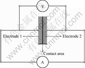
Fig. 1 Schematic diagram of impedance test system of electrode-electrode
3 Results and discussion
3.1 Etching time
Figure 2 shows that SEM images of surface structure of copper electrodes with about 40 ��m in thickness after etching process for different time. It can be seen that the surface of copper electrode presents uneven surface microstructures after etching process for 1 min and 10 min from Figs. 2(a) and (b). While, the size of surface microstructures of copper electrode after etching process for 10 min is significantly larger than the one after etching process for 1 min. After etching for 20 min, the copper electrode with uniform surface microstructure was obtained, as seen in Fig. 2(c). These surface microstructures will contribute to the improvement of contact condition between electrode and skin to reduce contact resistance. However, after etching for 30 min, the surface microstructures of copper electrode show the uneven size, as shown in Fig. 2(d). Moreover, it is found that the sizes of surface microstructures become larger after etching for 30 min. We speculate that it may result from the growth of crystal. Therefore, we can conclude that the etching time has a great influence on the surface microstructure of copper electrode. In order to obtain the uniform surface microstructure of the copper electrode, the etching time will be recommended to choose about 20 min.
In addition, the copper electrodes with the thickness of 60 and 100 ��m were used for etching under the same temperature conditions. The etching time was selected as 1, 5, 10, 20, and 30 min. The effect of etching time on the etching rate of copper electrodes with different thicknesses is shown in Fig. 3. According to the overall trend of plot, the etching rate was gradually decreased with increasing etching time for the copper electrodes with different thicknesses. Especially, the etching rate was decreased quickly in the starting stage within 5 min. Later, the etching rate was decreased slowly. Furthermore, the thickness had little influence on the etching rate. In the starting stage within 5 min of etching process, the copper electrode showed the larger etching rate. However, the etching rate was changed little for the copper electrodes with different thicknesses when the etching time was more than 10 min.
3.2 Etching temperature
To study the effect of etching temperature on the etching rate, the temperatures of thermostatic water tank were set as 30, 40, 50, and 60 ��. The copper electrodes with thicknesses of 40, 60, and 100 ��m were used for etching with 10 min. Figure 4 shows the effect of etching temperature on the etching rate of copper electrodes with different thicknesses. The etching rate was gradually increased with increasing etching temperature, but the etching rate was changed little at the same etching temperature for copper electrodes with different thicknesses. Moreover, it was found that the etching rate for the copper electrode with 40 ��m in thickness showed little higher etching rate. In addition, it is easy to produce the side etching phenomenon and jagged edges for copper electrode at the higher etching temperature in the etching process. So, the copper electrode presents the irregular shape after etching process. In order to prevent the occurrence of side etching phenomenon, the etching temperature should not be chosen too high after considering the etching rate.
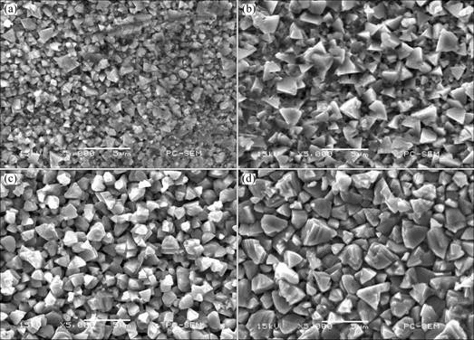
Fig. 2 SEM images of surface structure of copper electrodes with about 40 ��m in thickness after etching for different time: (a) 1 min; (b) 10 min; (c) 20 min; (d) 30 min
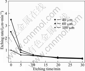
Fig. 3 Effect of etching time on etching rate of copper electrode with different thicknesses
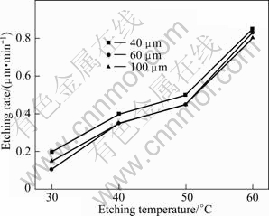
Fig. 4 Effect of etching temperature on etching rate of copper electrodes with different thicknesses
3.3 Etching liquid concentration
To study the effect of etching liquid concentration on the etching process of copper electrode, the ultra pure water was used to mix with five masses of copper chloride to get the etching liquids with different concentrations, as shown in Table 1. The copper electrodes with three thicknesses of 40, 60, and 100 ��m were used for etching process for 10 min in the etching liquid with different concentrations. Figure 5 shows the effect of etching liquid concentration on the etching rate of copper electrode with different thicknesses. From Fig. 5, it can be seen that the etching rate kept the similar value using the etching liquid of Formulation 1 and Formulation 2. Moreover, the etching rate was changed little using the etching liquid of Formulation 3, Formulation 4, and Formulation 5. On the whole, the etching liquid with higher concentration copper chloride will significantly speed the etching rate of copper electrode. However, once the concentration of copper chloride is more than the Formulation 3, the overall change of etching rate is very small. Therefore, we recommend to choose the etching liquid of Formulation 3 for the etching process of copper electrode.
Table 1 Chemical etching liquid with five formulations
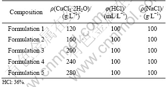
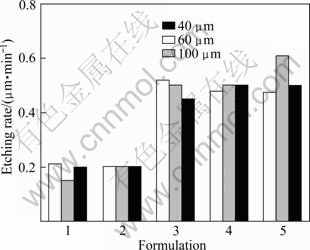
Fig. 5 Effect of etching liquid concentration on etching rate of copper electrode with different thicknesses
3.4 Geometric size
To analyze the effect of geometric size on the etching process, the copper electrode with five dimensions of 5 mm��5 mm, 10 mm��10 mm, 20 mm��20 mm, 30 mm�� 30 mm, 40 mm��40 mm in length��width were used for the etching process of 10 min. Figure 6 shows the etching rate of copper electrodes with different geometric sizes. It is found that the etching rates show small fluctuations for copper electrodes with different sizes. The value of etching rate is in the range of 0.4-0.45 ��m/min. The increase of etching time decreases the concentration of etching liquid component, leading to change of the etching rate. However, the experimental results show that the electrode size has little effect on the etching rate with enough etching liquid in etching process.

Fig. 6 Etching rate of copper electrode with different geometric dimensions
3.5 Alternating current impedance test
For the bioelectrical impedance measurement, the electrodes were typically used in high frequency environment. After choosing the high frequency (50 kHz) and low current (1 mA), the copper electrode fabricated by the etching process for 10 min at the etching temperature of 30 �� in etching liquid with Formulation 3 and Ag/AgCl disposable ECG electrode were used to carry out the alternating current impedance test of electrode-electrode for 24 h. Figure 7 shows the alternating current impedances of ECG and copper electrode-electrode. The impedance value of ECG electrode is increased quickly at the starting test stage of 2 h. Later, the impedance value of ECG electrode is increased slowly with the extension of testing time. Eventually, the impedance of ECG electrode is gradually got to level off. The whole change of impedance values is approximately 3 ��. These impedance characteristics will have an important influence on the measurement accuracy of bioelectrical impedance technology. Furthermore, the copper electrode is fabricated by the etching process to get a series of surface microstructures. These microstructures will help to form the stable contact when the electrode is used in the bioelectrical impedance technology. The testing result indicates that the copper electrodes presented stable alternating current impedance in the range of 0.5-0.6 �� within continuous testing of 24 h. Therefore, the stable properties of alternating current impedance help to improve the measurement accuracy of bioelectricity impedance technology.
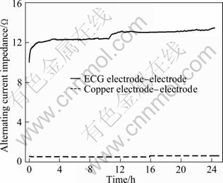
Fig. 7 Alternating current impedances of ECG and copper electrode
4 Conclusions
1) The chemical etching process was used to fabricate the copper electrode with a series of surface microstructures. The effect of the etching time, etching temperature, etching liquid concentration, and sample sizes on the etching rate and surface microstructures of copper electrode was studied by changing the etching processing parameters.
2) In the etching process, the etching rate for the copper electrode with different thicknesses is gradually decreased with increasing etching time, and is gradually increased with increasing etching temperature. Setting the etching time of 20 min, the copper electrode with a series of surface microstructures can be produced. Moreover, it is found that the etching rate is increased when the etching liquid concentration of copper chloride is increased. However, once the concentration is above the Formulation 3, the etching rate of copper electrode is changed little. The etching liquid of Formulation 3 is recommended to choose for the etching process of copper electrode. In addition, the etching processing experiment indicates that the geometric size has little influence on the etching rate of copper electrodes. After using the alternating current impedance test of electrode-electrode for 24 h, the impedance change of ECG electrode is approximately 3 ��. However, the copper electrode with a series of surface microstructures fabricated by the etching process presents a stable impedance value because of the reliable surface contact of electrode-electrode. Therefore, the copper electrode with stable alternating current impedance will help to improve the measurement accuracy of bioelectricity impedance technology.
References
[1] BROWN B H. Medical impedance tomography and process impedance tomography: A brief review [J]. Measurement Science & Technology, 2001, 12(8): 991-996.
[2] FAES T J C, van der NEIJ H A, de MUNCK J C, HEETHAAR R M. The electric resistivity of human tissues (100 Hz�C10 MHz): A meta-analysis of review studies [J]. Physiological Measurement, 1999, 20(4): R1-R10.
[3] DONG Xiu-zhen. The development of the bioelectric impedance technologies [J]. Chinese Journal of Medical Physics, 2004, 21(6): 311-317. (in Chinese)
[4] IRZMANSKA E, CHARLUSZ M, KUJAWA J, KOWALSKI J, PAWLICKI L, IRZMANSKI R. Using impedance plethysmography to evaluate antidecubital underlay systems for chronically immobilized patients [J]. Advances in Clinical and Experimental Medicine, 2010, 19(5): 637-651.
[5] TOWERS C M, MCCANN H, WANG M, BEATTY P C, POMFRETT C J D, BECK M S. 3D simulation of EIT for monitoring impedance variations within the human head [J]. Physiological Measurement, 2000, 21(1): 119-124.
[6] LISTON A D, BAYFORD R H, TIDSWELL A T, HOLDER D S. A multi-shell algorithm to reconstruct EIT images of brain function [J]. Physiological Measurement, 2002, 23(1): 105-119.
[7] ZENG Qiang, SUN Xiao-nan, WU Hong-mei, WANG Dong-ye, YANG Dan, ZHAO Jian-chuan, FAN Li, YE Ping. Relationship between body fat composition and cardiovascular disease risk factors: Bioelectrical impedance analysis [J]. Journal of Clinical Rehabilitative Tissue Engineering Research, 2008, 12(13): 2473-2476.
[8] GONG Wei-yan, L? Jing-hua, WANG Yan, SHA Hong, REN Chao-shi. Impedance property of electrodes used in bio-electrical impedance measurement [J]. Journal of Clinical Rehabilitative Tissue Engineering Research, 2009, 13(9): 1653-1656. (in Chinese)
[9] GRANOT Y, RUBINSKY B. Methods of optimization of electrical impedance tomography for imaging tissue electroporation [J]. Physiological Measurement, 2007, 28(10): 1135-1147.
[10] ZHANG J, PATTERSON R. Non-invasive determination of absolute lung resistivity in adults using electrical impedance tomography [J]. Physiological Measurement, 2010, 31(8): s45-s56.
[11] FU Feng, ZANG Yi-min, DONG Xiu-zhen, WANG Yue-min, YOU Fu-sheng, SHI Xue-tao, LIU Rui-gang. The variation of impedance spectrum of in vitro tissues after been isolated from the body [J]. Chinese Journal of Medical Physics, 2003, 20(4): 282-283. (in Chinese)
[12] WILKE N, O��BRIEN J, CASEY G, DOODY T, SODEN D, MORRISSEY A. Influence of electrode design on electric field distribution during electroporation [C]//The 3rd European Medical and Biological Engineering Conference, IFMBE Proc Prague, 2005, 11(1): 20-25.
[13] HUA P, WOO E J, WEBSTER J G, TOMPKINS W J. Using compound electrodes in electrical impedance tomography [J]. IEEE Transactions on Biomedical Engineering, 1993, 40(1): 29-34.
[14] KUHN A, KELLER T, LAWRENCE M, MORARI M. The influence of electrode size on selectivity and comfort in transcutaneous electrical stimulation of the forearm [J]. IEEE Transactions on Neural Systems and Rehabilitation Engineering, 2010, 18(3): 255-262.
[15] WANG Yan, SHA Hong, REN Chao-shi. Optimum design of electrode structure and parameters in electrical impedance tomography [J]. Physiological Measurement, 2006, 27(3): 291-306.(in Chinese)
[16] WANG Yan, SHA Hong, REN Chao-shi. Optimizing design of compound electrode structure parameter in electrical impedance tomography [J]. Biomedical Engineering and Clinical Medicine, 2007, 11(2): 91-96.
[17] PA Pai-shan. Selective removal technology using chemical etching and excimer assistance in precision recycle of color filter [J]. Transactions of Nonferrous Metals Society of China, 2011, 21(s1): s210-s214.
[18] FAN Li-mei, WEN Jiu-ba, ZHAO Sheng-li, ZHU Yao-min. Chemical etching on single-crystalline silicon slice and its surface morphology [J]. Surface Technology, 2007, 36(1): 19-21.
������迹ͭƬ�缫�Ļ�ѧ��ʴ����
�� ΰ, �� ��,������,����ƽ,������,�̵²�,������
��ɽ��ѧ ��ѧԺ������ 510006
ժ Ҫ��Ϊ��þ���ǿ�ȶ����ܵ�������迹�缫�����û�ѧ��ʴ�ӹ�������������������һϵ���ṹ�Ľ���ͭƬ�缫��ͨ���ı�ӹ����ղ����ķ��������ط�����ʴʱ�䡢��ʴ�¶ȡ���ʴҺ��Ũ�ȡ���Ʒ�ߴ�ȿ�ʴ���ղ�����ͭƬ�缫��ʴ�����ʺͱ����ṹ��Ӱ�졣�����������ʴ���ʽ����ſ�ʴʱ����ӳ������ͣ����ſ�ʴ�¶ȵ����߶������ߣ�����ʴ�����ߴ�Կ�ʴ���ʵ�Ӱ�첻��ѡ�ú��ʵĿ�ʴҺ��Ũ��(���3)�������������¿�ʴ20 min�����Ի�þ��зḻ�����ṹ��ͭƬ�缫�����⣬����24 h�缫�Խӵ������Խ����迹���ԣ����ĵ�缫��ȣ����û�ѧ��ʴ�ӹ���ͭƬ�缫�����ڱ�����зḻ�ı����ṹ�������γɿɿ��ı���Ӵ����Ӷ������ȶ��Ľ����迹ֵ��
�ؼ��ʣ�������迹��ͭƬ�缫����ѧ��ʴ�������ṹ�����ղ���
(Edited by YANG Hua)
Foundation item: Project (2011A090200123) supported by Industry-Universities-Research Cooperation Project of Guangdong Province and Ministry of Education of China; Project (111gpy06) supported by Fundamental Research Funds for the Central Universities, China; Project (101055807) supported by the Innovative Experiment Plan Project for College Students of Sun Yat-sen University, China
Corresponding author: ZHOU Wei; Tel: +86-20-39332148; E-mail: zhouw23@mail.sysu.edu.cn
DOI: 10.1016/S1003-6326(11)61347-2
Abstract: In order to obtain bioelectrical impedance electrodes with high stability, the chemical etching process was used to fabricate the copper electrode with a series of surface microstructures. By changing the etching processing parameters, some comparison experiments were performed to reveal the influence of etching time, etching temperature, etching liquid concentration, and sample sizes on the etching rate and surface microstructures of copper electrode. The result shows that the etching rate is decreased with increasing etching time, and is increased with increasing etching temperature. Moreover, it is found that the sample size has little influence on the etching rate. After choosing the reasonable etching liquid composition (formulation 3), the copper electrode with many surface microstructures can be obtained by chemical etching process at room temperature for 20 min. In addition, using the alternating current impedance test of electrode-electrode for 24 h, the copper electrode with a series of surface microstructures fabricated by the etching process presents a more stable impedance value compared with the electrocardiograph (ECG) electrode, resulting from the reliable surface contact of copper electrode-electrode.
