
J. Cent. South Univ. (2016) 23: 2268-2275
DOI: 10.1007/s11771-016-3284-9

Observer-based hybrid control algorithm for semi-active suspension systems
REN Hong-bin(�κ��)1, CHEN Si-zhong(��˼��)1, ZHAO Yu-zhuang(����׳)1,
LIU Gang(����)2, YANG Lin(����)1
1. School of Mechanical Engineering, Beijing Institute of Technology, Beijing 100081, China;
2. College of Mechanical & Electrical Engineering, Shenyang Aerospace University, Shenyang 110136, China
 Central South University Press and Springer-Verlag Berlin Heidelberg 2016
Abstract:
In order to improve ride comfort and handling performance of the vehicle, an adaptive hybrid control algorithm is proposed for semi-active suspension systems. The virtues of sky-hook is combined with ground-hook control strategies and a more suitable compromise for the suspension systems is chosen. The hybrid coefficient is tuned according to the longitudinal and lateral acceleration so as to improve the vehicle stability especially in high speed conditions. Damping continuous adjustable absorber is used to continuously control the damping force so as to eliminate the damping force jerk instead of traditional on-off control policy. Based on suspension stroke measured by sensors, unscented Kalman filter is designed to estimate the suspension states in real-time for the realization of hybrid control, which improves the robustness of the control strategy and is adaptive to different types of road profiles. Finally, the proposed control algorithm is validated under the following two typical road profiles: half-sine speed bump road and the random road. The simulation results indicate that the hybrid control algorithm could offer a good coordination between ride comfort and handling of the vehicle.
Key words:
semi-active suspension; hybrid control; unscented Kalman filter (UKF)��
1 Introduction
The roles of automobile suspension system are to support the vehicle body, keep vehicle occupants comfortable and well isolate from road disturbances for driving pleasure and safety. However, the vehicle ride comfort and handling stability for a passive suspension system is conflicting. In order to improve vehicle ride comfort, the suspension should be designed with low damping especially in the range of 4-8 Hz, which is the most sensitive frequency range of human body. But the low damping will cause the peak values of the suspension stroke and increase the probability of suspension breakdown. The low damping will also lead to the increase of vehicle dynamic wheel load, so it will decrease the tire road contacting ability and deteriorate the vehicle safety and stability [1]. A heavy damped suspension will present a good handling stability, but it will transfer much of the road disturbance energy to the vehicle body, and this will deteriorate the ride comfort for drivers. So, it is a deadlock for traditional passive suspension system because of its fixed characteristics of springs and dampers. Passive suspension design is a compromise between ride comfort and safety. Good tune and design of a passive suspension can to some extend optimize and tradeoff ride comfort quality and stability, but cannot eliminate these conflicts completely [2].
In recent years, controllable suspension systems have attracted considerable attentions by researchers and automobile industries, which can overcome some of limitations of traditional passive suspension systems. The controllable suspension can provide variable damping or spring forces, such as active suspension and semi-active suspension systems. Full active suspension can exert an independent force by the actuator to improve vehicle comfort and control vehicle body motion. The main drawbacks of the fully active suspension system are high energy cost and high frequency bandwidth requirement (more than 20 Hz). These drawbacks have limited its development and applications in automobile industry. A semi-active damper generates force in a passive manner, but the amount of force generated can be actively controlled [3]. The damping force is modulated in accordance with the operational conditions, which is controlled by certain logic from sensors connected to CPU [4]. The damping force can be adjusted by changing the orifice size or oil viscosity separately or continuously, such as damping continuously variable dampers [5], magneto-rheological suspension [6]. In addition, semi-active suspension is more stable and fail-safe; because it still can work under pure passive mode in case of control system failed. Due to its less energy consumption and better control priorities under extreme driving conditions, it has been considered as a good alternative between the active suspension and passive suspension systems [7-8].
A wide range of control techniques have been developed for active and semi-active suspension systems in last two decades. The sky-hook control strategy was proposed by KARNOPP et al [9], and since then many control strategies are proposed based on sky-hook logic [10-13]. An adaptive semi-active control algorithm combined with the online sprung mass estimation was proposed by SONG [14]. MORADI et al [15] designed an adaptive PID-sliding-mode fault-tolerant control for full car suspension control. Some intelligent approaches are also applied in the control because of the nonlinear and uncertainty characteristics of the vehicle, including neural networks [16] and genetic algorithms [17]. Although these intelligent approaches have been applied, the mathematical proof for stability is still difficult to demonstrate till now; and the system stability is more important especially for the active suspension.
The sky-hook control logic adjusts the damping force according to the direction of sprung mass vertical velocity and suspension stroke velocity. This logic is simple and robust to the variation of vehicle payload. The ideal sky-hook only dissipates energy from the mass of vehicle body, and the vibration of unsprung mass becomes excessive [18]. Of course, the realistic sky-hook damper is mounted between the wheel and vehicle body. The sky-hook controller improves the ride comfort significantly at the expense of the decreasing the handling safety; this will be explained in the following section. Conversely, the ground-hook control logic is aim to improve the safety and handling stability, and it is road friendly, but deteriorates the ride comfort. Even though neither of the two ideal controllers truly happens, we can still use this logic to design the suspension algorithm. The main motivation of this study is to combine virtues of sky-hook with ground-hook control strategies and propose an adaptive hybrid control algorithm to achieve a more suitable compromise for the semi-active suspension system. In order to eliminate the damping force jerk by using the traditional on-off control policy, continuous damping control logic is applied.
2 Suspension system and quarter car model
Vehicle ride comfort and handling stability are mainly determined by vertical dynamic behavior of suspension systems. Assuming that the motion of four wheels can be decoupled and we are only interested in the frequency of vertical dynamics (0-30 Hz), the quarter car suspension model is a good choice. The semi-active suspension model is shown in Fig. 1. The damping force is adjusted in real time according to designed control algorithm.
ms is the sprung mass of car body, including passenger, internal components and it may vary according to the passenger number and the payload condition of the car. It is supported by the suspension system including spring and damping absorber. The absorber is continuous adjustable damper, which can be adjusted by controlling the current of solenoid valve according to a given logic. The scheme of the damping continuously adjustable absorber is shown in Fig. 2 and the velocity-damping force characteristics are shown in Fig. 3. The variable damping force is achieved by controlling the flow rate and passage of the oil inside the damper. mu is the unsprung mass, which is supported by the tire modeled as liner spring with stiffness coefficient Kt. The displacements of sprung mass and unsprung mass are denoted as zs and zu, respectively; and the road profile is denoted as q. So, the dynamic equations of the nonlinear suspension can be described as
 (1)
(1)
 (2)
(2)

Fig. 1 Semi-active suspension
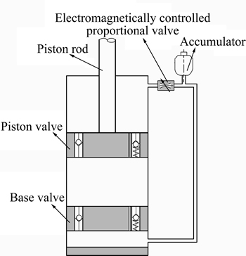
Fig. 2 Scheme of damping adjustable absorber
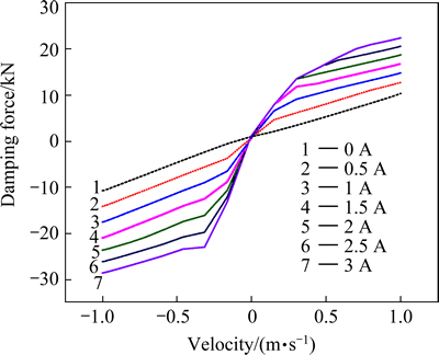
Fig. 3 Damping characteristics under control current
where Fc is controllable damping force; q is the road excitation input.
3 Hybrid control algorithm design based on observed state information
3.1 Hybrid control algorithm
The ideal sky-hook and ground-hook configurations are shown in Fig. 4 and Fig. 5, respectively. The ideal sky-hook is a comfort-oriented control policy, and the wheel motion becomes excessive since there is no damping applied to it. So, the vehicle handling stability will be deteriorated due to the loss of contact with the road surface. The ideal ground-hook controller is road-holding performances oriented, but this will deteriorate the ride comfort of the vehicle. In order to improve both ride comfort and handling stability, the hybrid control algorithm is proposed to reduce both resonant peak values of vehicle body and wheel. The practice hybrid control algorithm is accomplished as shown in Fig. 1.
The on-off sky-hook control logic can be expressed as

Fig. 4 Ideal sky-hook control configuration

Fig. 5 Ideal ground-hook control configuration
 (3)
(3)
where Csky is sky-hook reference damping coefficient.
The on-off ground-hook control logic can be expressed as
 (4)
(4)
where Cground is ground-hook reference damping coefficient.
The conventional on-off control logic is working according to the velocity direction of vehicle body and suspension stroke to choose a soft or hard damping mode. It will lead to a sharp increase or jump in damping force, which in turn, cause a jerk in vehicle body acceleration. This acceleration jerk causes a significant reduction in isolation benefits that should be offered by sky-hook controller [19]. In order to eliminate the damping force jerk, and improve both ride comfort and handling safety, the continuous hybrid control logic is designed.
The continuous hybrid control logic can be expressed as
 (5)
(5)
 (6)
(6)
where Cmax is the maximum damping coefficient which the damper can supply.
 (7)
(7)
Deeps and bumps cause the wheels to move up or down. Cornering, braking and acceleration can make the body lean to one side or pitch forward. Most of the time, these will deteriorate the vehicle handling stability, even safety. So, we use the hybrid coefficient �� to adjust the weight between sky-hook and ground-hook. Consider the following cases: when choose ��=1, the control policy will be pure skyhook focusing on the vehicle ride comfort. When choose ��=0, the control will be pure ground-hook focusing on vehicle handling stability and safety. In control algorithm, the hybrid coefficient is tuned according to the vehicle driving conditions in real time. Here the hybrid coefficient can be calculated by the longitudinal acceleration and lateral acceleration.
 (8)
(8)
where  and
and  are the normalized vehicle longitudinal and lateral acceleration, respectively.
Figure 6 plots the power spectral density (PSD) of vehicle body acceleration and tire dynamic load comparison under different hybrid coefficients and different control logics, respectively. It clearly indicates the benefits of hybrid control strategy for the vehicle ride comfort and handling safety.
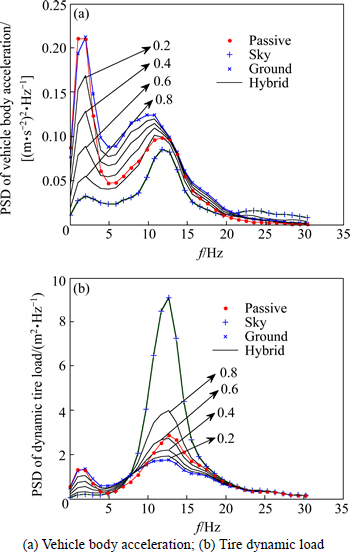
Fig. 6 PSD of tire dynamic load comparison under different �� values:
3.2 State observer based on unscented Kaman filter
The performance of controllable suspension can be further improved if accurate suspension state information could be obtained. In the paper, we will use the UKF to estimate the vehicle body velocity and tire vertical velocity in real time as shown in Fig.7.
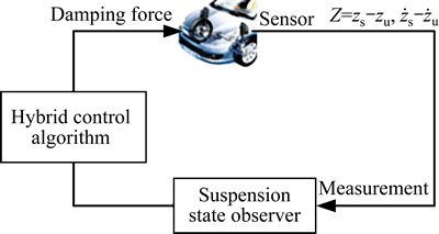
Fig. 7 Hybrid suspension controller with state observer
Some control algorithms assume that all states are measureable. But in practice, some states are difficult to be measured or cannot be measured at all due to the high cost and technology limits. So, it is necessary to design the observer to identify the states or parameters of the system. Extended Kalman filter (EKF) is an approximation to optimal estimation method for the nonlinear systems. It is based on the Taylor expansion theory and first order approximation to linearize the nonlinear system. It is difficult to calculate the Jacobi matrix especially for the strong non-linear systems [20]. The UKF is a nonlinear Kalman filter which avoids calculating the Jacobi matrix and shows superior accuracy compared with the EKF that works with a linearized model. And the computation load is almost same as EKF.
Let the state vector
 and observer measurement as y=
  Then, the dynamic function can be rewritten as
 (9)
(9)


 is the process noise, it is the derivative of road disturbance, and it is white noise with covariance Q; v is the observation noise which is assumed to be zero mean Gaussian white noise with covariance R.
  is vertical velocity of sprung mass;
  is vertical velocity of unsprung mass;
 is suspension relative displacement;
  is tire deflection;
  is vertical displacement of sprung mass;
  is vertical displacement of unsprung mass.
The continuous-time nonlinear system function (Eq. (9)) can be discretized as discrete-time nonlinear system function by using the first-order Taylor approximation as
 (10)
(10)
where ��T is the sampling time.
The sigma points are a set of points that has mean and covariance equal to the given mean and covariance. The elements are discrete in probability distribution. This distribution can be propagated exactly by applying the nonlinear function to each point. We use the symmetrical sampling method to pick up the sigma points. For the random variable state vector x, the mean is , the covariance of x is denoted as P x. The sigma points are chosen so that their mean and covariance to be exactly as and P x, respectively. Let ��k be a set of 2n + 1 sigma points (where n is the dimension of the system state vector) [22],
 (11)
(11)
Here,  is a scaling parameter. The constant �� determines the spread of the sigma around the
  , and is usually set to a small value
  SUB>
SUB> it makes sure that the covariance matrix is positive definite.
The details of UFK theory can be referenced from Refs. [21-22]. The UKF is based on the unscented transform (UT) theory and statistical linearization technique. This technique is used to deal with the nonlinear system with a random variable through a linear regression between n points drawn from the prior distribution of the random variable, named as sigma points. The detailed computation process has been listed in Algorithm 1.
Algorithm 1: UKF algorithm
Step 1: The sigma vectors are propagated through the nonlinear system function,
 (12)
(12)
Step 2: Measurement update
 (13)
(13)
The mean of the state vector  and the measurement value
 can be approximated by using a weighted sample of the sigma vectors,
 (14)
(14)
Step 3: Covariance update
The covariance of the state vectors and the measurement values can be calculated by
 (15)
(15)
The weight vector can be acquired by
 (16)
(16)
 (17)
(17)
Step 4: Correction
 (18)
(18)
1�� considers the high order moment of the prior distribution, for Gaussian distribution and ��=2 is optimal.
4 Simulation and discussion
In this section, the simulation model is built in Matlab/Simulation which is conducted to evaluate the dynamic behavior of the designed hybrid semi-active suspension control algorithm. The simulations are carried out on two typical road excitations: half-sine speed bump road and the random road. The speed bump road represents the discrete events of relatively short duration and high intensity; and the smooth random road represents consistent excitations with wide range of frequencies. Simulation parameters are listed in Table 1.
Table 1 Parameters of off-road vehicle suspension

Case 1: Half-sine speed bump road
The half-sine speed bump is with the height of 101.6 mm and the length of 3.5 m [23], and the vehicle velocity is kept as 10 m/s. the estimation results and control comparison are plotted in Figs. 8-11.
Figures 8 and 9 show suspension estimation results, compared with the reference values. We can find that the estimation results are precise. The hybrid control logic is working according to the estimated suspension states to tune the damping force of the controllable suspension.Figures 10 and 11 show the results of vehicle running over the half-sine speed bump. We can find that the sky-hook controller is working well not only for the vehicle body motion, but also for the tire dynamic load. But for the ground-hook control strategy, it will cause bad performance for both of them. This is because that the ground-hook control strategy is effective for the high frequency excitation; but it is invalid for the low frequency excitation, such as speed bump road, this phenomenon can also be found in Fig. 6(b). We can also find that, the hybrid controller is better compared with the passive suspension.
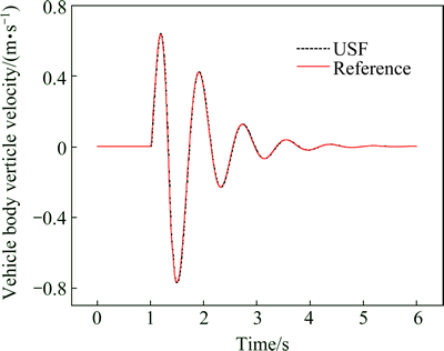
Fig. 8 Estimation results of vehicle body vertical velocity
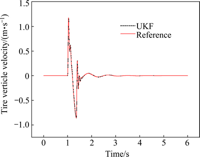
Fig. 9 Estimation results of tire vertical velocity
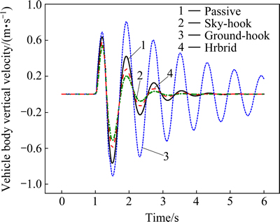
Fig. 10 Vehicle body vertical velocity comparison

Fig. 11 Tire dynamic load comparison
Case 2: Random road excitation
In this section, the rough road excitation model in both time and frequency domains is presented. The ISO has proposed a series of standards of road roughness classification by using the power spectral density (PSD) values (ISO 1982); the PSD of the random road excitation can be expressed as
 (19)
(19)
where n is the space frequency in m-1; n0 is the reference space frequency, n0 = 0.01 m-1; Gq(n0) is the road roughness coefficient; w is frequency index, it reflects the frequency structure of the pavement, usually w=2.
The road random excitation model is built by integrated Gaussian white noise. The equation of random road in time domain can be expressed as [24]
 (20)
(20)
where W(t) is the Gauss white noise; n00 is the low cut-off space frequency, n00 = 0.001 m-1; u is the vehicle driving speed.
Figures 12 and 13 show the control comparison results under random road excitation with the constant vehicle speed 20 m/s. From the simulation results, it can be concluded that the hybrid control algorithm can constrain both vehicle body vibration and tire dynamic load. It could tradeoff vehicle ride comfort and safety perfectly.
Table 2 lists the root mean square (RMS) comparison of three suspension performance indexes under different control strategies. Even though, the hybrid control algorithm is not the best one among of them for each suspension performance index, it excellently coordinate the suspension performance indexes and make sure good ride comfort and driving safety.
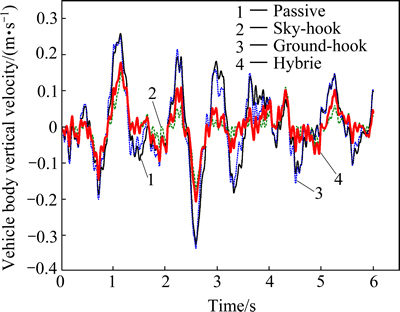
Fig. 12 Time history of vehicle body vertical velocity comparison
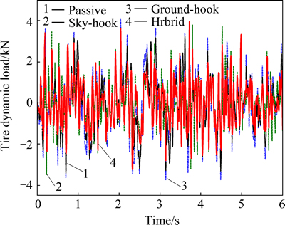
Fig. 13 Tire dynamic load comparison
Table 2 RMS comparison for different control strategies

5 Conclusion and future works
1) A hybrid control algorithm for semi-active suspension was developed to coordinate the vehicle ride comfort and handling safety. This control strategy is combined with the sky-hook and ground-hook by tuning the hybrid coefficient.
2) The suspension state observer is designed for the hybrid control algorithm based on the UKF theory.
3) Two typical road excitation tests are implemented to validate the proposed control algorithm. Simulation results indicate that the hybrid algorithm can excellently coordinate the vehicle ride comfort and handling stability.
4) Future work should concentrate on developing semi-active suspension control algorithms for full vehicle suspension including pitch and roll motion and validating the designed control algorithms in real vehicle tests.
References
[1] KOCH G, KLOIBER T. Driving state adaptive control of an active vehicle suspension system [J]. IEEE Transactions on Control Systems Technology, 2014, 22(1): 44-57.
[2] AHMADIAN M E H D I, DAVID E, SIMON. An analytical and experimental evaluation of magneto rheological suspensions for heavy trucks [J]. Vehicle System Dynamics, 2003, 37(S): 38-49.
[3] PARE C A. Experimental evaluation of semiactive magneto-rheological suspensions for passenger vehicles[D]. Blacksburg: Virginia Polytechnic Institute and State University, 1998.
[4] LAJQI S, STANISLAV P. Designs and optimizations of active and semi-active non-linear suspension systems for a terrain vehicle [J].  Vestnik-Journal of Mechanical Engineering, 2012, 58(12): 732-743.
[5] HEO S J, PARK K, SON S H. Modelling of continuously variable damper for design of semi-active suspension systems [J]. International Journal of Vehicle Design, 2003, 31(1): 41-57.
[6] REN H, CHEN S, FENG Z, LIU G. Study on fuzzy control based on magneto-rheological semi-active suspension [C]// Proceedings of the Third International Conference on Mechanic Automation and Control Engineering. Now York: IEEE Computer Society, 2012: 3539-3542.
[7] CHEN Y, WANG Z, QIU J, HUANG H. Hybrid fuzzy skyhook surface control using multi-objective microgenetic algorithm for semi-active vehicle suspension system ride comfort stability analysis [J]. Journal of Dynamic Systems, Measurement, and Control, 2012, 134(4): 1-13.
[8] KASHEM, S B A, MEHRAN E, ROMESH N. Comparison between different sets of suspension parameters and introduction of new modified skyhook control strategy incorporating varying road condition [J]. Vehicle System Dynamics, 2012, 50(7): 1173-1190.
[9] KARNOPP D, CROSBY M J, HARWOOD R A. Vibration control using semi-active force generators [J]. Journal of Manufacturing Science and Engineering, 1974, 96(2): 619-626.
[10] CHIANG H, LEE L. Optimized virtual model reference control for ride and handling performance-oriented semi-active suspension systems [J]. IEEE Transactions on Vehicular Technology, 2015, 64(5): 1679-1690.
[11] HONG K S, SOHN H C, HEDRICK J K. Modified skyhook control of semi-active suspensions: A new model, gain scheduling and hardware-in-the-loop tuning [J]. Journal of Dynamic Systems, Measurement, and Control, 2002, 124(1): 158-167.
[12] ASSADSANGABI B, EGHTESAD M, DANESHMAND F. Hybrid sliding mode control of semi-active suspension systems [J]. Smart Materials and Structures, 2009, 18(12): 125027.
[13] YAO Jia-ling, SAIED T, TIAN Song-mei, ZHANG Zhong-nan, SHEN Liang. A novel semi-active suspension design based on decoupling skyhook control [J]. Journal of Vibroengineering, 2014, 16(3): 1318-1325.
[14] SONG X, AHMADIAN M, SOUTHWARD S. An adaptive semiactive control algorithm for magnetorheological suspension systems [J]. Journal of Vibration and Acoustics, 2005, 127(5): 493-502.
[15] MORADI M, AFEF F. Adaptive PID-sliding mode fault tolerant control approach for vehicle suspension systems subject to actuator faults [J]. IEEE Transactions on Vehicular Technology, 2014, 63(3): 1041-1054.
[16] GUO D L, HU H Y, YI J Q. Neural network control for a semi-active vehicle suspension with a magnetorheological damper [J]. Journal of Vibration and Control, 2004, 10(3): 461-471.
[17] SUN Lu, CAI Xi-ming, YANG Jun. Genetic algorithm-based optimum vehicle suspension design using minimum dynamic pavement load as a design criterion [J]. Journal of Sound and Vibration, 2007, 301(1): 18-27.
[18] REICHERT B A. Application of magnetorheological dampers for vehicle seat suspensions [D]. Blacksburg: Virginia Polytechnic Institute and State University, 1997.
[19] AHMADIAN M, SONG X, SOUTHWARD S C. No-jerk skyhook control methods for semiactive suspensions [J]. Journal of Vibration and Acoustics, 2004, 126(4): 580-584.
[20] NORGAARD, M, NIELS K. POULSEN, OLE R. New developments in state estimation for nonlinear systems [J]. Automatic, 2000, 36(11): 1627-1638.
[21] REN Hong-bin, CHEN Si-zhong, SHIM T. Effective assessment of tyre�Croad friction coefficient using a hybrid estimator [J]. Vehicle System Dynamics, 2014, 52(8): 1047-1065.
[22] JULIER S J, UHLMANN J K. Unscented filtering and nonlinear estimation [J]. Proceedings of the IEEE, 2004, 92(3): 401-422.
[23] CHEN B C, SHIU Y H, HSIEH F C. Sliding-mode control for semi-active suspension with actuator dynamics [J]. Vehicle System Dynamics, 2011, 49(1-2): 277-290.
[24] WU Zhi-cheng, CHEN Si-zhong, YANG Lin, ZHANG Bin. Model of road roughness in time domain based on rational function [J]. Transaction of Beijing Institute of Technology, 2009, 29(9): 795-798. (in Chinese)
(Edited by DENG L��-xiang)
Foundation item: Projects (51375046, 51205021) supported by the National Natural Science Foundation of China
Received date: 2015-05-26; Accepted date: 2015-11-15
Corresponding author: ZHAO Yu-zhuang, PhD, Lecturer; Tel: +86-10-68911343; E-mail: zyz1112@163.com
Abstract: In order to improve ride comfort and handling performance of the vehicle, an adaptive hybrid control algorithm is proposed for semi-active suspension systems. The virtues of sky-hook is combined with ground-hook control strategies and a more suitable compromise for the suspension systems is chosen. The hybrid coefficient is tuned according to the longitudinal and lateral acceleration so as to improve the vehicle stability especially in high speed conditions. Damping continuous adjustable absorber is used to continuously control the damping force so as to eliminate the damping force jerk instead of traditional on-off control policy. Based on suspension stroke measured by sensors, unscented Kalman filter is designed to estimate the suspension states in real-time for the realization of hybrid control, which improves the robustness of the control strategy and is adaptive to different types of road profiles. Finally, the proposed control algorithm is validated under the following two typical road profiles: half-sine speed bump road and the random road. The simulation results indicate that the hybrid control algorithm could offer a good coordination between ride comfort and handling of the vehicle.
