锗单晶中位错密度的影响因素
北京有色金属研究总院北京国晶辉红外光学科技有限公司
摘 要:
直拉法生长的空间太阳能电池用锗单晶中位错密度的影响因素有:籽晶中位错延伸对晶体中位错密度的影响;温度梯度对位错密度的影响;固液界面形状对位错密度的影响;机械因素对位错密度的影响。通过dash技术排除籽晶中位错的影响;通过调整晶体所处的热场(改变埚位和保温筒高度)、改变熔体中轴向负温度梯度的状况(增加坩埚杆的保温效果和开双加热器)和通过设计出轴向温度梯度为线性温度梯度径向温度梯度较小的热场来减小温度梯度对位错密度的影响;通过调整固液界面形状(改变拉速、埚转和晶转)来改善由于固液界面形状不佳带来的位错增值现象。通过上述措施可以基本消除单晶中位错排、位错堆以及小角晶界,得到低位错密度的单晶。
关键词:
中图分类号: O772
作者简介:左建龙(1980-),男,河北邢台人,硕士;研究方向:晶体生长,通讯联系人,(E-mail:zjlong719@126.com);
收稿日期:2009-11-20
基金:国防科工委科研基金资助项目(MKPT-2004-48ZD);
Influence Factors of Germanium Monocrystal Dislocation Density
Abstract:
The factors that affected dislocation density of single crystal which used to produce space solar battery of Czochralski method included: dislocation extension in the seed crystal,temperature gradient,solid-liquid interface shape and mechanism factors.The effect of dislocation in the seed crystal was eliminated by dash technology.The influence of temperature gradient on dislocation density was reduced through changing the state of negative temperature gradient(enhance the insulation of crucible pole and use double heaters),adjusting the location of crystal in the thermal field(change the location of crucible and the height of insulation cylinder) and designing thermal field with linear temperature gradient in axial direction and smaller temperature gradient in radial direction.The propagation of dislocation caused by imperfect shape of solid-liquid interface was improved by adjusting the shape of solid-liquid interface(change crystal growth rate,crystal rotation rate and crucible rotation rate).Through the measures above,low dislocation density crystal without dislocation emission,dislocation pile and small-angle grain boundary could be obtained.
Keyword:
germanium monocrystal;low dislocation density;solar cells;temperature gradient;
Received: 2009-11-20
在过去的几十年里, 锗一直是作为光电半导体材料为人们所关注
直拉锗单晶生长中, 从引晶到收尾过程都有可能产生位错, 而热场和工艺参数都会对晶体中的位错密度产生很大的影响。
本文探讨了通过改善热场和拉晶工艺参数, 使锗单晶达到低位错密度。 锗单晶中位错的产生来源于籽晶中位错的延伸和生长和降温过程中热应力产生的位错, 针对这两个方面进行了如下实验。
1 实 验
采用TDR80单晶炉进行实验, 设计了两套不同的热场, 采用不同的工艺参数进行低位错单晶拉制实验, 采用<100>偏向无位错籽晶, 经过引晶、 细颈、 放肩、 等径和收尾5个步骤拉制出锗单晶, 然后进行位错密度检测, 通过对不同热场和工艺参数条件下制得的单晶的位错密度比较得出结论。
2 结果与讨论
2.1 籽晶中位错延伸对晶体中位错密度的影响
对各种蚀坑和生长图形的考察以及滑移线的形成, 早已证明位错是可动的。 现在已经能够在电子显微镜下用透射法直接观察在薄膜中运动的位错
金刚石结构的锗单晶中位错的滑移面为{111}面。 当以<100>晶向生长时, 滑移面与生长轴的最小夹角θ为36.16°。 位错沿滑移面延伸和产生滑移, 因此位错要延伸、 滑移至晶体表面而消失, 细颈工艺通常采用高拉速将晶体直径缩小。 在这种条件下, 冷却过程中热应力很小, 不会产生新的位错。 因此, “缩颈”是排除籽晶中的位错的好方法。 细颈的最小长度L与直径D的关系可由下式表示:
L>Dctgθ (1)
式中, θ为滑移面与生长轴的最小夹角。 高拉速可形成饱和点缺陷。 在这种条件下, 位错很容易通过攀移传播到晶体表面。 实践发现, 重掺锑晶体细颈粗而短就可以消除位错, 可能是通过攀移机制实现的。 在籽晶能承受晶锭重量的前提下, 细颈应尽可能细长
考虑到细颈时热应力的影响, 细颈应该比理论计算值要长出很多
表1 细颈长度与单晶中位错密度的关系
Table 1Relations between dislocation density and neck length
| Neck length/mm | 100 | 150 | 300 | 400 | 500 | |
| EDP/cm2 | Ⅰ | 1500 | 800 | 40 | 40 | 20 |
| Ⅱ | 400 | 500 | 80 | 20 | 20 | |
从表1中可以看出, 当细颈长度达到300 mm长后, 位错密度降到100/cm2以下, 若再加长细颈长度, 密度也没有明显变化, 所以细颈长度不要超过300 mm, 从经济和时间方面考虑, 将细颈长度控制在300 mm左右。
通过实验发现, 细颈之前单晶头部的位错密度很高, 而且有小角晶界和位错排的出现(图1(a)), 经过细颈之后(图1(b)), 单晶的头部小角晶界和位错排消失, 位错密度也明显降低。 图1是细颈之前与细颈之后的头部的位错分布图, 从图上可以看出经过细颈后, 位错密度明显降低了, 可见细颈是排除籽晶中位错的有效方法。
2.2 固液界面对位错密度的影响
晶体生长过程中界面的稳定性, 涉及晶体生长过程能否得到良好的控制, 平坦且稳定的生长界面才能保证生长出低位错的单晶
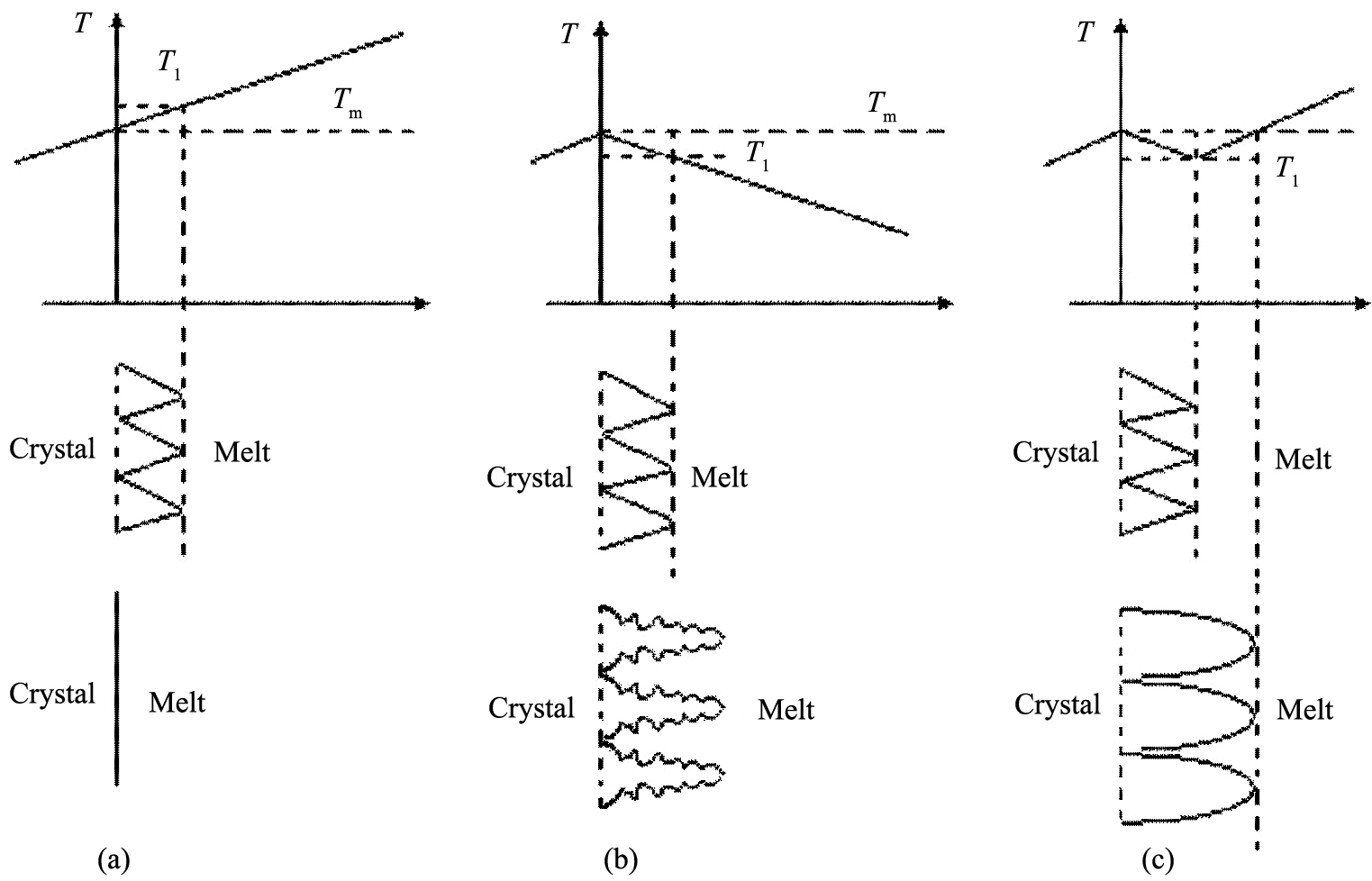
假设固液界面原为一平面, 来考虑熔体中的温度分布对界面稳定性的影响。 在固液界面前沿的熔体中, 其温度分部通常可以设想有3种形式。 一种是越离开界面温度越高, 也就是说取坐标方向从界面指向熔体内部的温度梯度是正的。 在这种温度分布下, 由于固液界面的温度可以近似地认为是凝固点温度Tm, 故所有熔体的温度都高于凝固点, 因而称熔体为过热熔体, 如图2(a)所示, 这种温度分布不会使晶体产生位错, 但也不能生长晶体。 第二种温度分布如图2(b)所示, 温度梯度是负的, 所有熔体都为过冷熔体, 在这种温度梯度下, 很容易产生枝晶, 晶体生长是不可控制的。 第三种温度分布的特征是, 熔体中的温度不是单调地改变, 虽然远离固液界面的熔体仍为过热熔体, 但在固液界面邻近存在一个狭小的过冷区, 如图2(c)所示, 只有在这种温度梯度下才能生长出低位错密度的单晶。 所以我们设计热场必须保证温度保持这种梯度。
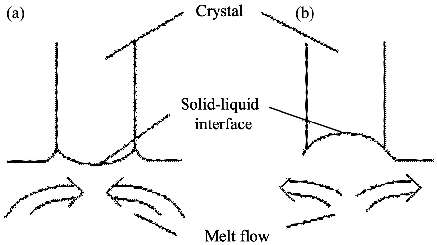
如果忽略过冷效应, 生长界面的宏观形状应该与由温度场所确定的温度等于熔点的等温面完全吻合, 正常情况下, 界面可呈现凸向熔体、 凹向熔体和平坦3种情况, 在晶体直径较大的情况下也可呈现双曲面形状, 其变化取决于生长系统中热量传输的情况和晶体尺寸。 在通常拉晶条件下, 生长界面的形状见图3。 在拉晶过程中, 通过调节晶体的提拉速率, 晶体转速和坩埚转速, 可调整界面形状。 增加晶体的提拉速率可使凹向熔体的生长界面曲率增大。 加大晶转使坩埚底的热流更快地流向界面, 可以起到与增加提拉速率类似的作用。 生长界面的形状对单晶中位错密度有很大的影响
图1 细颈前后的位错分布图
Fig.1 Distribution of dislocation before and after dash (a) Distribution of dislocation before dash; (b) Distribution of dislocation of dislocation after dash
图2 温度分布对界面稳定性的关系
Fig.2 Relations of temperature distribution and the interface stability
(a)Crystal interface stability in positive temperature gradient;(b)Crystal interface stability in negative temperature gradient;(c)Crystal interface stability in the correct temperature gradient
实验中发现, 固液界面比较平坦时, 位错密度就较小。 固液界面较凸或凹都会使位错密度增大(如表2所示)。
2.3 温度梯度对位错密度的影响
温度梯度
热场设计是单晶生长中最重要的环节, 热场设计的科学与否直接影响晶体的生长形态, 设计一个合理的热场是生长低位错单晶的前提条件。
热场系统包括石墨加热器、 石墨坩埚、 石墨支架、 石墨-碳毡保温罩、 石墨保温盖和石墨电极, 其中加热器是热场的主体。
2.3.1 晶体生长对热场的要求
图3 熔体的流动对固液界面形状的影响
Fig.3 Influence of melt flow to solid-liquid interface shape
(a) Solid-liquid interface shape of concave to melt; (b) Solid-liquid interface shape of convex to melt
表2 固液界面形状与位错密度的关系
Table 2Relationship between solid-liquid interface shape and the dislocation density
| Solid-liquid interface shape |
Dislocation density of head/cm2 |
Dislocation density of tail/cm2 |
| Flat | 700 | 600 |
| Concave | 1300 | 1700 |
| Flat | 800 | 500 |
| Convex | 1200 | 2300 |
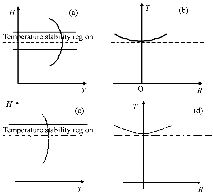
为满足对于相变驱动力, 避免新核形成, 保证晶体的完整和均匀性的要求, 对热场的基本要求是: 生长界面附近的熔体具有一定的过冷度, 而界面附近以外的熔体必须高于熔点; 在熔体中, 径向温度梯度应适当地小, 轴向温度梯度应适当地大, 传统的单加热器热场中的径向和纵向温度分布图如图4(a), (b)所示。 采用单加热器时, 热场中央温度最高, 中间有一段温度稳定递减的区域, 超出这个区域, 温度迅速降低, 所以采用双加热器来弥补并增加这个区域的长度, 采用双加热器后, 轴向温度梯度得到了明显的改善。 经过多次试验测定发现双加热器的轴向和径向温度分布如下图4(c), (d)所示, 从图中可以看出双加热器的温度稳定区域得到了加长, 而温度梯度也明显的得到了改善。
2.3.2 热场的设计
单晶炉生产厂家在单晶炉出厂时, 一般都附有热场, 但为了能够生产出低位错晶体, 需要重新设计热场。
首先, 由晶体直径和投料量决定石墨坩埚的直径和高度, 从而决定加热器的直径和高度; 加热器应有合适的电阻值, 从而保证一定的加热功率熔化全部锗料; 满足拉晶要求的径向和轴向温度梯度; 结构简单, 便于加工, 温场的重复性好。 加热器的总电阻与电源变压器的额定电流和额定电压
图4 热场中的轴向和径向温度分布fields
Fig.4 Axial and radial distribution of temperature in thermal
(a)The axial distribution of temperature in thermal fields of single heater;(b)The radial distribution of temperature in thermal fields of single heater;(c)The axial distribution of temperature with thermal fields of double heater;(d)The radial distribution of temperature in thermal fields with double heater
相匹配, 使其达到最佳的输出功率。 其次, 在满足上述条件的基础上, 设计出轴向和径向温度梯度更合理的热场, 使温度稳定区域尽可能地长, 必要时可采用双加热器甚至多加热器。 最后, 通过保温来改善温度梯度, 得到理想的温度梯度。
3 结 论
1. 直拉法生长的锗单晶中位错排、 位错堆、 小角晶界的产生主要是由于晶体在生长过程中受到较大的热冲击, 产生较大的热应力, 或者是因为晶体所处热场不佳表里收缩不一致造成的。 另外, 可能是因为熔体中的温度梯度不合适, 或产生负温度梯度, 导致固液界面不稳定, 造成热应力, 最终使位错密度增大。
2. 通过调整晶体所处的热场(改变埚位和保温筒高度)、 改变熔体中纵向负温度梯度的状况(增加坩埚杆的保温效果和开双加热器)或者调整固液界面形状(改变拉速、 埚转和晶转), 可以基本消除单晶中位错排、 位错堆以及小角晶界, 得到低位错密度的单晶。
参考文献


