

J. Cent. South Univ. (2020) 27: 1939-1955
DOI: https://doi.org/10.1007/s11771-020-4421-z

Dynamic effect of heavy-haul train on seismic response of railway cable-stayed bridge
ZHU Zhi-hui(��־��)1, 2, GONG Wei(����)1, WANG Kun(����)1, LIU Yu(����)1,DAVIDSON Michael T3, JIANG Li-zhong(������)1
1. School of Civil Engineering, Central South University, Changsha 410075, China;
2. Key Laboratory of Engineering Structure of Heavy Railway of Ministry of Education,Changsha 410075, China;
3. Bridge Software Institute, Engineering School of Sustainable Infrastructure and Environment,University of Florida, Gainesville, USA
 Central South University Press and Springer-Verlag GmbH Germany, part of Springer Nature 2020
Abstract:
This paper focuses on understanding and evaluating the dynamic effect of the heavy-haul train system on the seismic performance of a long-span railway bridge. A systematic study on the effect of heavy-haul trains on bridge seismic response has been conducted, considering the influence of vehicle modeling strategies and dynamic characteristics of the seismic waves. For this purpose, the performance of a long-span cable-stayed railway bridge is assessed with stationary trains atop it, where the heavy-haul vehicles are modeled in two different ways: the multi-rigid body model with suspension system and additional mass model. Comparison of the bridge response in the presence or absence of the train system has been conducted, and the vehicle loading situation, which includes full-load and no-load, is also discussed. The result shows that during the earthquake, the peak moment of the main girder and peak stress of stay cables increase by 80% and by 40% in the presence of fully loaded heavy-haul trains, respectively. At the same time, a considerable decrease appears in the peak acceleration of the main girder. This proves the existence of the damping effect of the heavy-haul train system, and this effect is more obvious for the fully loaded vehicles. Finally, this paper proposes an efficient vehicle modeling method with 2 degrees of freedom (DOF) for simplifying the treatment of the train system in bridge seismic checking.
Key words:
train-bridge interaction; heavy-haul train; cable-stayed bridge; earthquake; live load��
Cite this article as:
ZHU Zhi-hui, GONG Wei, WANG Kun, LIU Yu, DAVIDSON Michael T, JIANG Li-zhong. Dynamic effect of heavy-haul train on seismic response of railway cable-stayed bridge [J]. Journal of Central South University, 2020, 27(7): 1939-1955.
DOI:https://dx.doi.org/https://doi.org/10.1007/s11771-020-4421-z1 Introduction
Current design documents provide inconsistent guidance in regards to the treatment of the vehicle live load in the seismic analysis of bridges. For example, China Railway Bridge Seismic Design Code requires that the additional force caused by the train load should be taken as a part of the design load, where the vertical force is counted as 100% of the train load, and the lateral force is 50% [1]. While the Japanese railway design specification treats the lateral force as 10% of the train load [2]. Besides the inconsistency, the application range of these codes is restricted to the bridges whose span is usually within 120 m. For the long-span bridges beyond this range, a project-specific solution is needed, as recommended in AASHTO [3]. The effect of the train loads becomes more significant when it comes to the heavy-haul railways. As the heavy-haul trains usually have a marshaling of 10000 to 20000 t [4], which might be 20% or more of the dead load of the main girder for long-span bridges. Therefore, it is necessary to study the effect of the vehicle live load on seismic performance of the bridge and find an operable train model to the application of practical engineering, especially for long-span bridges in heavy-haul railways.
In the case of highway bridges, design procedures for bridges in most countries do not require the consideration of vehicle live loads in the seismic analysis [5]. But for research purpose, some efforts have been devoted to investigate the influence of vehicle live load on bridge seismic response [6-11]. Most of these studies focus on the seismic performance of highway bridges or viaducts in the presence of road vehicles, and they have proved that the specifications might be conservative or unconservative in some particular situations [8]. It provides some references to some extent for the influence of the train load on the seismic responses of railway bridge. However, the dynamic characteristics and mass distribution of heavy-haul trains are very different from those of road vehicles, and the design principles and specifications of highway bridges and railway bridges also vary significantly [12, 13]. Therefore, conclusions for the previous research of highway bridges and road vehicles might not be directly used to the railway system.
Limited studies for railway bridges have been conducted for this issue. HE et al [14] used a train-bridge coupled model to study the response of the Shinkansen system under moderate earthquakes. It was reported that when considering the train merely as additional mass, it may overestimate or underestimate the bridge response. By studying the seismic response and performance of straddle-type pre-stressed concrete bridges considering train load under moderate earthquakes, KIM et al [15] claimed that there is a damping effect for the high-speed train on the bridge during earthquakes. Recently, the analytical study of ZENG et al [16] confirmed that the particular position of the moving cars on the deck affects the response/safety of the vehicle significantly when an earthquake happens. However, the above studies have been conducted on high-speed railways. In fact, the running speed of heavy-haul trains is usually around 60-100 km/h, and the riding comfort is not so vital as it is for high-speed trains. Moreover, the axle load of high- speed vehicles is only 1/5 of that of heavy-haul vehicles. Therefore, differences between the two vehicle types in terms of dynamic characteristics should not be ignored. Considering the complexity of the train-bridge coupling system, it is not clear whether the above conclusions are still applicable.
Therefore, this study aims to evaluate the seismic performance of a long-span railway bridge in the presence of heavy-haul trains atop them and find a simplified train model for the practical engineering. The world��s first triple-tower cable- stayed railway bridge for heavy haul trains is selected as the bridge model. Two vehicle modelling strategies and two vehicle loading states are discussed. The first vehicle modelling method adopts the multi-rigid dynamics theory, where the springs and dampers of the primary and secondary suspension systems are considered, and the spatial relationship of the car body and the bogies are also taken into account. The second vehicle modelling method uses only additional masses attached to the bridge point, neglecting the interaction between trains and the bridge. The vehicle loading situations are fully loaded and no-loaded heavy-haul trains, which would cause a notable shift in heavy-haul vehicle dynamics characteristics. Further, this paper proposed a 2-DOF vehicle model for bridge seismic checking, which is sufficient to simulate the effect of train system on bridge seismic performance and can be used in practical engineering to simplify the treatment of train live load.
2 Dynamic equations of motion for train- bridge coupled system under earthquake
2.1 Vehicle model
For the vehicle model, several assumptions are adopted in this paper, as shown in many previous studies [14, 17-19]. Each vehicle usually consists of one cay body, four wheel-sets, two bogies, primary suspension connecting the wheel-set to the bogies and secondary suspension systems connecting to the car body. These car bodies are considered rigid, neglecting their elastic deformations during vibration. The primary and secondary suspension system are both idealized by identical linear springs and two similarly viscous dashpots in the longitudinal direction, horizontal direction, and vertical direction, respectively. As shown in Figure 1, each car body and bogie have five degree of freedoms (DOFs): lateral (Y), rolling (��), yawing (��), vertical (Z), and pitching (��), which are sufficient to capture the vehicle components [20, 21].
For the train-bridge coupled system, a more detailed model, including the wheel-track contact, is preferable in order to examine the motion of the train accurately. In this paper, it is assumed that the wheel-sets are always in contact with the bridge structure due to the fact that the adopted ground motions are of moderate-intensity, and the focus of this study is the bridge response [6, 22], which means no separation/uplifting in the normal direction and no sliding in the tangential direction between the wheel and bridge.
In total, each vehicle of the train is modelled using 15 independent DOFs. The equations of motions of the whole train system are expressed in the general form:
 (1)
(1)
where MV, CV, KV are mass, damping and stiffness matrices of the train system, respectively, which are symmetric and established by assembling the corresponding matrix of all vehicles because each vehicle of the train is independent of the adjacent vehicle within the DOFs concerned.  ,
, XV are time-varying acceleration, velocity and displacement vectors of the train system; FV is the force vector of the train system.
2.2 Bridge model
In this study, spatial vibration responses of the bridge are estimated using the finite element method. The 3D beam element, 3D link element, shell element and other particular elements are used for modelling individual components for different bridge structures. Accordingly, the equations of motion of the bridge are written as:
 (2)
(2)
where displacement, velocity and acceleration vectors are denoted as XB, and
and , respectively; FB is the external force vector of the bridge subsystem; MB, CB and KB are the mass, damping and stiffness matrices of the bridge subsystem. For the long-span cable-stayed bridge, the pre-tensions of the cables and the self-weight of the bridge lead to large internal forces of the bridge elements.
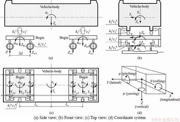
Figure 1 Vehicle model:
Therefore, the geometric nonlinearity should be taken into account in order to obtain the bridge response accurately. The stiffness matrix of the bridge system can be expressed as:
KB=KE+K0+KNL (3)
where KE is the elastic stiffness matrix, which is determined by the material properties of the bridge structure; K0 is the initial stress matrix caused by the initial internal force in elements; KNL is the geometric non-linear stiffness matrix, which is calculated according to the time-varying nodal displacement.
2.3 Train-bridge coupled model under earthquake
Considering the interactive force and wheel load at the contact points, the train-bridge coupled system is firstly developed. The equations of motion for the system under seismic excitation are written as:

 (4)
(4)
where FV is the dynamic wheel load vector of a train; FB is the external load vector caused by the train on the bridge; FEA is the seismic equivalent load vector acting on the bridge; CBB, CBV, KBB and KBV indicate coupling damping and stiffness matrices of the train-bridge interaction system, respectively. The Newmark-�� method is adopted to solve the simultaneous differential equations of the coupled system.
3 Numerical models
3.1 Description of cable-stayed bridge
The Dongting Lake Railway Cable-Stayed Bridge belongs to the West Inner Mongolia-Central China Railway, and it is the first triple-tower cable-stayed railway bridge in the world. As shown in Figure 2, the overall length of the bridge is 1288 m, with the two main spans measured at 406 m and the two side spans at 98 and 140 m, respectively. The full height of the towers is 157 m, and the height of the towers above the deck is 113.5 m. The superstructure consists of a box-truss composite structure, with members made of Q370qE grade steel. The superstructure is also fitted with 156 stay cables (excluding stabilizing cables), forming multiple double-plane systems that support the bridge deck at 14 m intervals. The 164 stay cables are divided into eight groups, ranging from 241 to 409 galvanized steel wires per cable, with wire diameter of 7 mm and tensile strength of 1860 MPa.
The bridge towers are Y-shaped, containing upper, middle, and lower tower columns and lower beams. Each tower consists of three cross sections at different heights. The concrete for these towers has a compressive strength of 50 MPa. The stay cables are numbered sequentially from the side to the main span, as shown in Figure 2. The deck is 21 m in width and 2.34 m in height, including two longitudinal steel-box girders along the deck edges with steel cross girders at 3.5 m intervals. Under the deck, longitudinal U-shape stiffeners are used to strengthen sections and prevent buckling problems from the flat steel box girder.
3.2 Finite element model of cable-stayed bridge
As shown in Figure 3, the 3D dynamic FE model of the cable-stayed bridge (CSB) is developed in ANSYS [23]. In this model, the towers and steel trusses are modeled using BEAM188 element, which utilizes actual cross- section properties based on the assumption of linear elastic. Tower bases are fixed in all degrees of freedom. Moreover, the long-stay cables participate much in the response of large-scale cable-stayed bridges subjected to dynamic load [24, 25]. Therefore, in order to accurately simulate the cable force and get the local vibration response, the multiple-element cable system (MECS) method is used to simulate the cable [26], in which each stay cable is divided into 20 elements. The geometric distances between cable ends and the cross-section centroids of the towers are represented by rigid bars. The details of deck modeling are provided in Ref. [27].
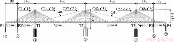
Figure 2 Elevation schematic of Dongting Lake Railway Bridge (Units: m)

Figure 3 Finite element model of Dongting Lake Railway Bridge
3.3 Modelling of heavy-haul train
For each vehicle of the train, two modelling methods are described in this section, namely space dynamic model based on the multi-body dynamics (as shown in Section 2.1) and the additional mass model, which ignores the dynamics of the vehicle and only considers inertia mass attributable to the vehicle. The schematic diagram of the two modeling methods is shown in Figure 4. The main properties of the vehicle C80 are listed in Table 1.
3.4 Ground motions
In order to investigate the seismic response of the train-bridge coupled system, three seismic waves belonging to different site soil are used in this paper. They are Tianjin wave, El Centro wave, and Kobe wave, which correspond to the site soil types of soft soil, moderate soil and stiff soil, respectively, according to the Chinese design code. In the place where the bridge was actually built, the site soil type of this bridge is close to the spectral characteristics of El Centro wave used in this paper, as shown in Figure 5. The peak ground acceleration (PGA) is in line with the seismic ground motion parameters zonation map of China [28], in which the PGA is set as 0.10g. Therefore, the maximum accelerations in this analysis are normalized as 0.10g in the horizontal direction and 0.05g in the vertical direction, as shown in Figures 6-8.
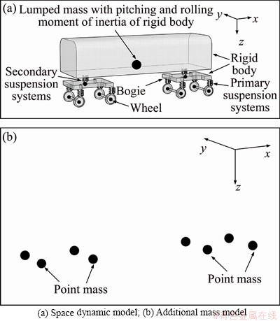
Figure 4 Different vehicle simulation methods:
Table 1 Properties of vehicles C80
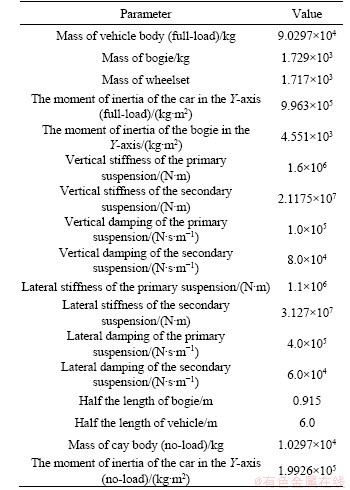
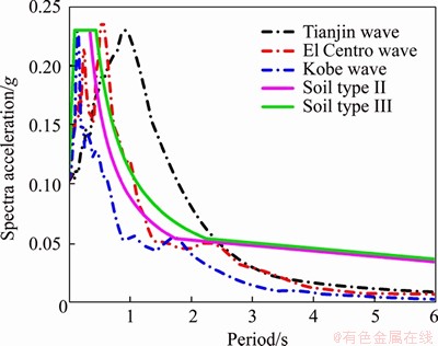
Figure 5 Comparison of spectrum characteristics
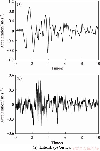
Figure 6 Time history of Tianjin wave:
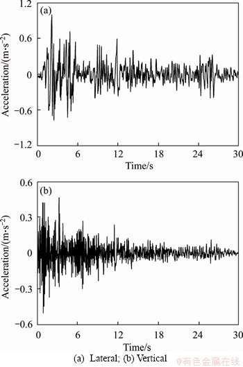
Figure 7 Time history of El Centro wave:

Figure 8 Time history of Kobe wave:
4 Results and discussion
4.1 Case simulation
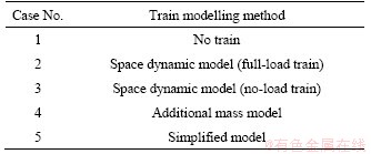
As discussed above, in order to investigate the effect of train dynamics on the seismic response of CSB, five cases are described in this section according to the different vehicle modeling methods, as shown in Table 2. The spatial dynamic model in cases 2 and 3, and the additional mass model in case 4 are corresponding to methods introduced in Section 3.3. The details of the simplified model are in Section 4.4. From cases 2 to 5, the train consists of 100 stationary vehicles (1 locomotive+48 trailers+2 locomotives+48 trailers+1 locomotive), occupying the entire length of the CSB. Figure 9 sketches the position of the train system from cases 2 to 5. The first two vertical circular frequencies of vibration of each numerical model, i.e., ��1=1.76 rad/s and ��2=2.01 rad/s, are used to calculate the Rayleigh damping coefficients, with the damping ratio of 0.02.
Table 2 Different cases simulation
The above cases are all examined by three seismic waves introduced in Section 2.4, with time step of 0.01 s. It is noteworthy that this study intends to discuss the effect of the dynamics of the train system on the response of bridge. Therefore, the situation of vehicles running on the bridge is not considered.
4.2 Dynamic characteristics analysis
4.2.1 Vehicle
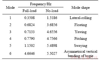
This section describes the dynamic characteristics of the vehicle model based on the spatial dynamic model. Table 3 lists the first six natural frequencies and the corresponding vibration modes of the vehicle system. Also, Figure 10 sketches the first six mode shape of the vehicle model. It can be seen from Table 2 and Figure 4 that the first five frequencies of the full-load heavy-haul vehicle are below 1.2 Hz. For no-load vehicle, the decrease in the mass and moment of inertia of the car body turns out higher natural frequencies.
4.2.2 Train-bridge coupled system
The modal analysis is used to assess the effect of the train system on the frequency of the CSB.

Figure 9 Position of stationary train system
Table 3 Vehicle dynamic characteristics
The modal analysis in cases 1 and 2 is pursued concerning different static equilibrium states, which are acquired by a geometric non-linear static analysis with initial stress applied to the main cables and gravities to all the members of the structure. Table 4 compares the model analysis results in cases 1 and 2.
It can be seen from Table 4 the natural vibration frequencies of the CSB are quite low, and the vibration modes are closely concentrated, from which the former fifteen modals distributed under 1.3 Hz. The train system not only plays a role in lowering the frequencies (16.99% at most in the 13th mode shape of symmetric vertical bending of the main girder) but also altering the distribution of mode shape.
4.3 Influence of train on bridge response under earthquake
The dynamic performance of the bridge is evaluated in three ways: the envelopes of acceleration and the bending moment of the main girder; the shear force of bearing of the middle tower; the tensions of all stay cables. This section compares the calculation results of cases 1, 2 and 3.
The envelopes of lateral and vertical acceleration of CSB main girder are plotted in Figures 11 and 12, respectively, in which the abscissa denotes in the distance along with the starting point of the bridge. It can be seen that the stationary full-load train has a significant damping effect on the seismic response of the bridge, both on the lateral and vertical directions. However, the no-load train not only has a weak lateral vibration reduction effect but also increases the peak value of vertical acceleration at particular positions of the main girder. This effect can be explained by the TMD theory: the mass damper with large mass ratio (damper/structure) generally has stronger robustness [28]. In this study, the mass ratio of the full-load train and the main girder reaches about 24%, while the mass ratio of the no-load train and the main girder is only about 4.8%. Therefore, as a series of mass damper without optimal design, the no-load train may amplify the response of bridge under the excitation of some particular main frequency seismic waves [29].
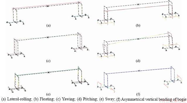
Figure 10 First six mode shapes of vehicle C80:
Table 4 Comparison of dynamic characteristics for first fifteen global modes
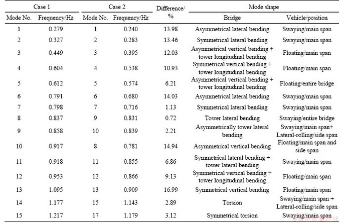
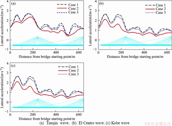
Figure 11 Envelopes of lateral acceleration of main girder:
Figure 13 sketches the envelopes of the moment of the main girder during the earthquake. It is seen from Figure 13 that the presence of the train system will increase the peak moment of the main girder: the peak negative moment of T2 bearing obtained by full-load train and no-load train models are 2.0 times and 1.2 times, respectively, of that obtained by the CSB model. The peak moment in the middle of the main span of full-load and no-load train models are 2.5 times and 1.3 times as much as that of the CSB model, respectively. Further, it can be seen from Figure 13 that the differences among the envelopes of bridge bending moment obtained under three kinds of normalized seismic excitations are very small. Therefore, it can be inferred that for the cases studied in this paper, the peak moment of the main girder mainly depends on the structure mass, which is the sum of bridge mass and the train mass, due to the different seismic waves with the same PGA.
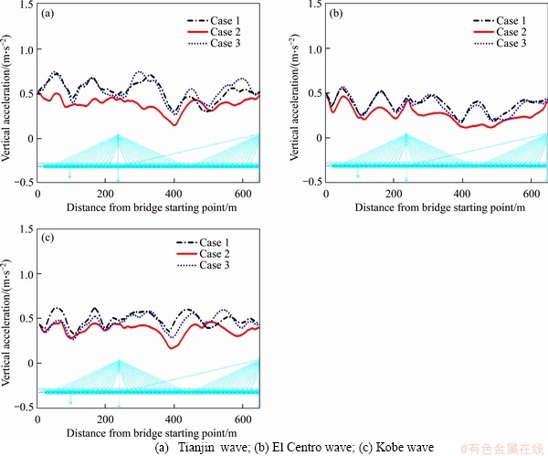
Figure 12 Envelopes of verticle acceleration of main girder:

Figure 13 Envelopes of moment of main girder:
Figure 14 illustrates the time history for the shear force of bearing T1, and Table 5 lists the root mean square (RMS) and the peak value of shear force. Compared with the results of different cases, the peak shear force decreases to varying degrees due to the presence of the train dynamic system, although there is a considerable increase in the inertia of the main beam. This confirms that significant energy is absorbed or dissipated by the train system during the earthquake.
Figure 15 shows the peak stress of stay cables during earthquakes. Similar to the main girder bending moment, the peak stress of stay cables is mainly affected by the dead load of bridges, and the peak stress of stay cables will increase significantly with the presence of the train. In fact, there are some differences in the increased range of different cables, which is also the result of the redistribution of cable tension caused by the train system to a certain extent.
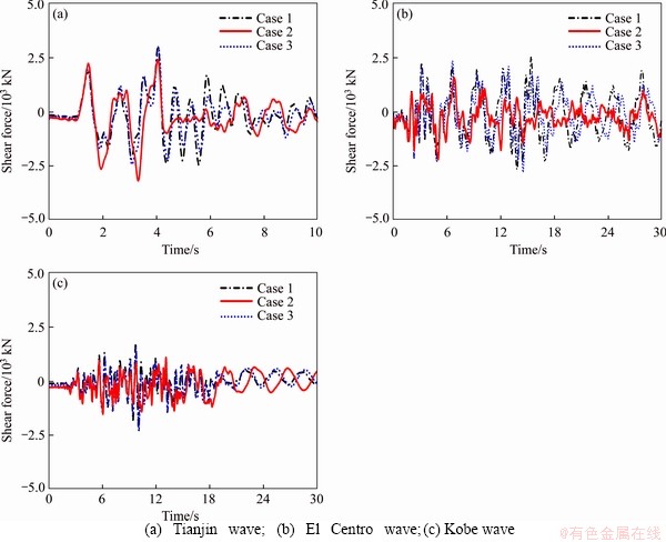
Figure 14 Shear force of bearing T1:
Table 5 RMS and peak value of shear force of T1 bearing (unit: kN)
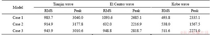
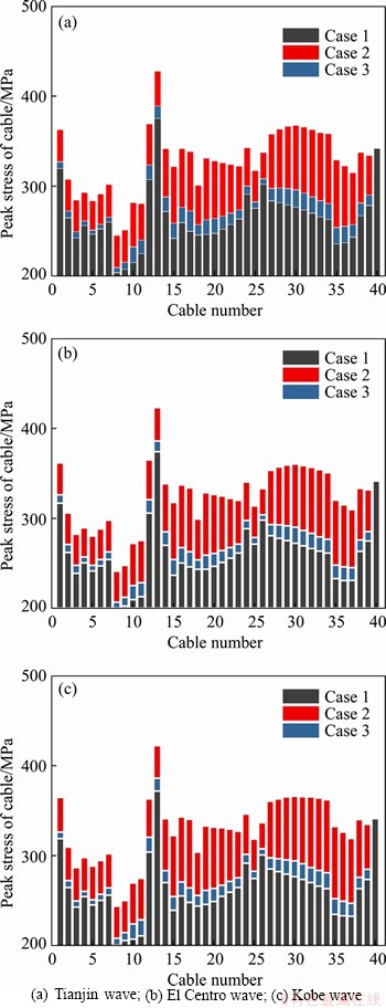
Figure 15 Peak stress of stay cables:
4.4 Influence of train simulation method on bridge response
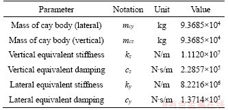
This section is corresponding to cases 2, 4 and 5. The only difference among them is the method of vehicle modelling, in which case 5 adopts a simplified train system, and each vehicle is simplified into a 2-DOF model. This is because, according to the results in Sections 4.2 and 4.3, it can be found that the dynamic train system could act as a mass damper, and for each heavy-haul vehicle, the main modes are floating and swaying of the car body. Therefore, the vehicle model for seismic checks can be modeled as a 2-DOF system, where the equivalent point mass (by using MASS21 in ANSYS) has the degrees of freedom of lateral (Y) and vertical (Z), as shown in Figure 16. The parameter of mass is the summary of the mass of the car body and bogies. The Equivalent spring- damper element (by using CONBIN14 in ANSYS) is used to connect the equivalent point mass to the bridge, with the corresponding equivalent stiffness and damping coefficient calculated through the primary and secondary suspension system. The main parameters of the simplified vehicle model are shown in Table 6.

Figure 16 Simplified vehicle model
Table 6 Properties of simplified vehicle model C80
The envelopes of lateral and vertical acceleration of the main girder are shown in Figures 17 and 18. It is seen from Figures 17 and 18 that, in most cases, treating train as additional mass overestimates the acceleration response of the bridge. Meanwhile, the results of cases 2 and 5 are in good agreement, which proves the applicability of the simplified vehicle model for seismic analysis of bridges.
Figure 19 plots the time-history of the shear force of bearing T1. And the RMS and peak shear force of bearing T1 are summarized in Table 7. Once again, it confirms that the train dynamic system absorbs and dissipates considerable energy under earthquake, and it is impossible to accurately simulate this effect by merely simplifying the vehicle as additional mass. Because the simplified vehicle in case 5 can reflect the dynamic characteristics of the vehicle under earthquake, the results of the bearing shear force are very close to those of case 2. Because of the geometric nonlinearity of stay cables, this section still compares the peak stress of stay cables with respect to the vehicle simulation method in Figure 20. The results show that all three vehicle simulation methods can be used to evaluate the stress of stay cables.

Figure 17 Envelopes of lateral acceleration of main girder:
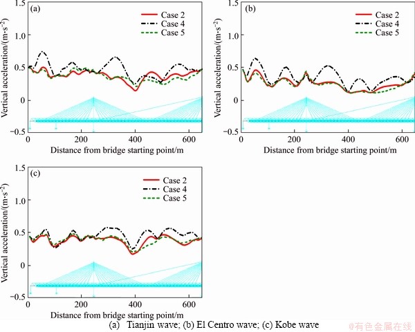
Figure 18 Envelopes of vertical acceleration of main girder:
According to the discussions above, the vehicle-bridge coupling dynamic system under earthquake is very complicated; the response of the system depends on the dynamic characteristics of bridges, trains, and ground motions. In this study, considering the vehicle effects does not lead to consistent underestimation or overestimation on the seismic response of bridge. Therefore, it is too arbitrary to neglect train loads or train dynamic effects for analyzing the peak bending moment of the main girder and the local response such as bearing shear force and acceleration of the main girder nodes. However, this study also suggests it is not necessary to adopt the complicated vehicle model for seismic checks of bridges, and the vibration-mode-shape-based simplified model can meet the requirement.

Figure 19 Time histories of shear force of T1 bearing:
Table 7 RMS and peak value of shear force of bearing T1 (unit: kN)
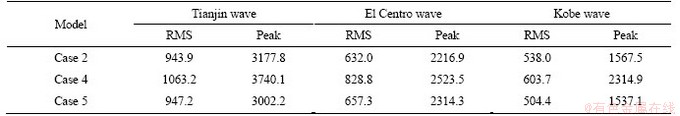

Figure 20 Peak stress of stay cables:
5 Conclusions
In this paper, the seismic response of a long-span cable-stayed bridge for heavy-haul railways is studied. Based on the different vehicle modeling strategies, a variety of train-bridge coupled models are established. Comparing with the bridge performances under different seismic waves, the conclusions are as follows:
1) The train system will significantly affect the dynamic response of the CSB under earthquake. In the presence of the train system, the peak acceleration of the main girder will generally decrease, while the peak force of stay cables and bending moment of the main girder will increase significantly.
2) There is a significant damping effect of the full-load heavy-haul train, whose working mechanism is similar to a series of mass dampers. Nevertheless, the no-load train leads to inconsistent results, which might amplify the seismic response of bridges. This is because mass dampers with large mass ratio usually have stronger robustness.
3) Considering vehicles as additional mass can only accurately evaluate the bridge bending moment and peak stress of stay cables under earthquake, but it will overestimate the bridge acceleration and bearing shear force. For bridge seismic performance check, not only train load but also train dynamic effect should be considered comprehensively.
4) The simplified vehicle simulation method proposed in this paper is convenient and efficient, which is also able to consider the dynamic effect of the train system. It can provide a reference for bridge design.
References
[1] GB 50111 2009. Code for seismic design of railway engineering [S]. (in Chinese)
[2] Japan Road Association. Design specifications of highway bridges, Part V seismic design [R]. Maruzen, Tokyo, Japan, 2002.
[3] AASHTO. AASHTO LRFD bridge design specifications [M]. 7th ed. Washington, DC: AASHTO, 2014.
[4] CAI Xiao-pei, ZHONG Yang-long, HAO Xiao-cheng, ZHANG Yan-rong, CUI Ri-xin. Dynamic behavior of a polyurethane foam solidified ballasted track in a heavy haul railway tunnel [J]. Advances in Structural Engineering, 2019, 22(3): 751-764. DOI: 10.1177/1369433218799154.
[5] WIBOWO H, SANFORD D, BUCKLE I, SANDERS D. Effect of live load on the seismic response of bridges [R]. Nevada: University of Nevada, 2013.
[6] BORJIGIN S, KIM C W, CHANG K C, SUGIURA K. Nonlinear dynamic response analysis of vehicle-bridge interactive system under strong earthquakes [J]. Engineering Structures, 2018, 176, 500-521. DOI: 10.1016/ j.engstruct.2018.09.014.
[7] KIM C W, KAWATANI M, KONAKA S, KITAURA R. Seismic responses of a highway viaduct considering vehicles of design live load as dynamic system during moderate earthquakes [J]. Structure and Infrastructure Engineering, 2011, 7(7, 8): 523-534. DOI: 10.1080/15732479.2010. 493339.
[8] KAMESHWAR S, PADGETT J E. Effect of vehicle bridge interaction on seismic response and fragility of bridges [J]. Earthquake Engineering & Structural Dynamics, 2018, 47(3): 697-713. DOI: 10.1002/eqe.2986.
[9] PARASKEVA T S, DIMITRAKOPOULOS E G, ZENG Q. Dynamic vehicle�Cbridge interaction under simultaneous vertical earthquake excitation [J]. Bulletin of Earthquake Engineering, 2017, 15(1): 71-95. DOI: 10.1007/ s10518-016-9954-z.
[10] SHABAN N, CANER A, YAKUT A, ASKAN A, KARIMZADEH N A, DOMANIC A, CAN G. Vehicle effects on seismic response of a simple-span bridge during shake tests [J]. Earthquake Engineering & Structural Dynamics, 2015, 44(6): 889-905. DOI: 10.1002/eqe.2491.
[11] SIRINGORINGO, DIONYSIUS M, FUJINO Y. Lateral stability of vehicles crossing a bridge during an earthquake [J]. Journal of Bridge Engineering, 2018, 23(4): 04018012. DOI: 10.1061/ (ASCE)BE.1943-5592.0001211.
[12] JIN Zhi-bin, PEI Shi-ling, LI Xiao-zhen, QIANG Shi-zhong. Vehicle-induced lateral vibration of railway bridges: an analytical-solution approach [J]. Journal of Bridge Engineering, 2015, 21(2): 04015038. DOI: 10.1061/ (ASCE)BE.1943-5592.0000784.
[13] KHAN E, LOBO J A, LINZELL D G. Live load distribution and dynamic amplification on a curved prestressed concrete transit rail bridge [J]. Journal of Bridge Engineering, 2018, 23(6): 04018029. DOI: 10.1061/(ASCE)BE.1943-5592. 0001236.
[14] HE Xing-wen, KAWATANI M, HAYASHIKAWA T, MATSUMOTO T. Numerical analysis on seismic response of Shinkansen bridge-train interaction system under moderate earthquakes [J]. Earthquake Engineering and Engineering vibration, 2011, 10(1): 85-97. DOI: 10.1007/s11803-011- 0049-1.
[15] KIM Chul-woo, ONO Kazuyuki, KAWATANI Mitsuo, ENMEI Takuya. Seismic performance of straddle-type monorail pre-stressed concrete bridges considering interaction with train under moderate earthquakes [C]// Proceedings of the 9th International Conference on Structural Dynamics. Porto: European Association for Structural Dynamics, 2014: 1161-1168.
[16] ZENG Qing, DIMITRAKOPOULOS E G. Seismic response analysis of an interacting curved bridge-train system under frequent earthquakes [J]. Earthquake Engineering & Structural Dynamics, 2016, 45(7): 1129-1148. DOI: 10.1002/eqe.2699.
[17] MONTENEGRO P A, NEVES S G M, CALCADA R, TANABE M, SOGABE M. Wheel�Crail contact formulation for analyzing the lateral train�Cstructure dynamic interaction [J]. Computers & Structures, 2015, 152: 200-214. DOI: 10.1016/j.compstruc.2015.01.004.
[18] ZHU Zhi-hui, GONG Wei, WANG Li-dong, HARIK I E, BAI Yu. A hybrid solution for studying vibrations of coupled train�Ctrack�Cbridge system [J]. Advances in Structural Engineering, 2017, 20(11): 1699-1711. DOI: 10.1177/ 1369433217691775.
[19] ZHAI Wan-ming, HAN Zhao-ling, CHEN Zhao-wei, LING Liang, ZHU Sheng-yang. Train�Ctrack�Cbridge dynamic interaction: A state-of-the-art review [J]. Vehicle System Dynamics, 2019, 57(7): 984-1027 DOI: 10.1080/00423114. 2019.1605085.
[20] CHEN G, ZHAI Wan-ming. A new wheel/rail spatially dynamic coupling model and its verification [J]. Vehicle System Dynamics, 2004, 41(4): 301-322. DOI: 10.1080/ 00423110412331315178.
[21] ZHANG Nan, XIA He. Dynamic analysis of coupled vehicle�Cbridge system based on inter-system iteration method [J]. Computers & Structures, 2013, 114: 26-34. DOI: 10.1016/j.compstruc.2012.10.007.
[22] ZENG Qing, YANG Yeong-bin, DIMITRAKOPOULOS E G. Dynamic response of high speed vehicles and sustaining curved bridges under conditions of resonance [J]. Engineering Structures, 2016, 114: 61-74. DOI: 10.1016/ j.engstruct.2016.02.006.
[23] ANSYS. ANSYS workbench modeling guide release 17.0 [M]. Canonsburg, PA: ANSYS Inc, 2017.
[24] CAMARA A, EFTHYMIOU E. Deck-tower interaction in the transverse seismic response of cable-stayed bridges and optimum configurations [J]. Engineering Structures, 2016, 124: 494-506. DOI: 10.1016/j.engstruct.2016.06.017.
[25] NI Y Q, WANG J Y, LO L C. Influence of stabilizing cables on seismic response of a multispan cable-stayed bridge [J]. Computer-Aided Civil and Infrastructure Engineering, 2005, 20(2): 142-153. DOI: 10.1111/j.1467- 8667.2005.00383.x.
[26] ZARATE B A, CAICEDO J M. Effects of cable dynamics in the modeling of cable-stayed bridges under seismic excitation [J]. International Journal of Structural Stability and Dynamics, 2015, 15(4): 1450061. DOI: 10.1142/ S0219455414500618.
[27] ZHU Zhi-hui, WANG Li-dong, DAVIDSON M T, , HARIK I E, PATIL A. Nonlinear dynamic analysis of long-span cable-stayed bridges with train�Cbridge and cable coupling [J]. International Journal of Advanced Structural Engineering, 2019: 1-13. DOI: 10.1007/s40091-019-0229-1.
[28] HOANG N, FUJINO Y, WARNITCHAI P. Optimal tuned mass damper for seismic applications and practical design formulas [J]. Engineering Structures, 2008, 30(3): 707-715. DOI: 10.1016/j.engstruct.2007.05.007.
[29] LI Jian-zhong, SU Mu-biao, FAN Li-chu. Vibration control of railway bridges under high-speed trains using multiple tuned mass dampers [J]. Journal of Bridge Engineering, 2005, 10(3): 312-320. DOI: 10.1061/(ASCE)1084-0702(2005) 10:3(312).
(Edited by ZHENG Yu-tong)
���ĵ���
�����г�ϵͳ�Ķ���ЧӦ����·б���ŵ�����Ӧ��Ӱ��
ժҪ������Ϊ�����������г�ϵͳ�Ķ���ЧӦ�Դ�����·����������Ӧ��Ӱ�죬�о��������г���ֹ����·б������ʱ�Ķ��������Լ�������Ӧ�������˻��ڶ������ѧ�Ŀռ䳵��ģ���븽������ģ�����ֲ�ͬ�ķ�ʽ�Գ������н�ģ�������п����������ļ��η����ԣ��������������������ֵģ�⡣�ڶԱ�����������µ�������Ӧʱ�����������ػ��������Լ����ص����ء�����������ڵ�����ʱ�����ص��г���ʹ����������Լ�������������ֵ�ֱ�����80%��40%�����������ļ��ٶȷ�ֵ��������½���֤���������г�����һ������ЧӦ���Ҹ�����ЧӦ���������г���˵��Ϊ�������ڴ˻����ϣ������һ������������������ļ�2���ɶȳ���ģ�ͣ���֤������ɿ��ԡ�
�ؼ��ʣ���-������������г���б���ţ������г�����
Foundation item: Project(51678576) supported by the National Natural Science Foundation of China; Project(2017YFB1201204) supported by the National Key R&D Program of China
Received date: 2019-12-25; Accepted date: 2020-05-08
Corresponding author: WANG Kun, PhD, Lecturer; Tel: +86-18874751908, E-mail: vtkwang@163.com; ORCID: 0000-0001-6061- 3069
Abstract: This paper focuses on understanding and evaluating the dynamic effect of the heavy-haul train system on the seismic performance of a long-span railway bridge. A systematic study on the effect of heavy-haul trains on bridge seismic response has been conducted, considering the influence of vehicle modeling strategies and dynamic characteristics of the seismic waves. For this purpose, the performance of a long-span cable-stayed railway bridge is assessed with stationary trains atop it, where the heavy-haul vehicles are modeled in two different ways: the multi-rigid body model with suspension system and additional mass model. Comparison of the bridge response in the presence or absence of the train system has been conducted, and the vehicle loading situation, which includes full-load and no-load, is also discussed. The result shows that during the earthquake, the peak moment of the main girder and peak stress of stay cables increase by 80% and by 40% in the presence of fully loaded heavy-haul trains, respectively. At the same time, a considerable decrease appears in the peak acceleration of the main girder. This proves the existence of the damping effect of the heavy-haul train system, and this effect is more obvious for the fully loaded vehicles. Finally, this paper proposes an efficient vehicle modeling method with 2 degrees of freedom (DOF) for simplifying the treatment of the train system in bridge seismic checking.
