

Effect of impinging angle and rotating speed on erosion behavior of aluminum
A. K. JHA, R. BATHAM, M. AHMED, A. K. MAJUMDER, O. P. MODI, S. CHATURVEDI, A. K. GUPTA
Advanced Materials and Processes Research Institute, Bhopal-462026, India
Received 27 January 2010; accepted 15 April 2010
Abstract:
Commercial aluminum (grade 1900) in rotary motion was exposed to slurry of sand in water. Samples were mounted at various angles and rotated at different speeds. Wear rate was calculated using mass loss measurement. The results show that wear rates increase with increasing impingement angle up to 90��. Contrary to the conventional understanding of maximum loss of ductile material at about 45�� impingement angle, maximum wear rate was observed in case of the aluminum sample fixed at 90��. However, increasing rotation speed of the samples results in exponential increase in wear rate. The findings are substantiated with the metallographic study of worn surface.
Key words:
aluminum; slurry erosion; impinging; wear;
1 Introduction
Erosion is described as the progressive loss of original material from a solid surface due to mechanical interaction between the surface and a fluid which may be a multi-component fluid or impinging solid or liquid particles. It is common that the materials used in pipes, bends and tank, etc in industries like chemical, cement, mining and mineral processing and thermal power plants encounter erosion related problems. Pulveriser mill components, multiple port outlet, orifice, PF bends, elbow, burner assembly, pressure parts, ID fan blade and coal ash slurry pipes are the main components affected by erosion in thermal power stations. There has always been attempt to reduce the material loss due to erosion as it incurs huge loss of the material. In the past few decades, researchers have focused on the study of material loss in order to conserve material and energy[1]. A wide variety of methods were adopted to protect materials from the nuisance of wear, including use of efficient materials[2], processing techniques[3], surface treatment[4-5] of the exposed components and use of engineering skills leading to less impact of wear on the material, such as appropriate impingement angle of erodent and velocity of slurry. Methodology to be followed for protection of material is adopted from the conclusions drawn from the simulated test carried out for the purpose. Investigations and studies provide insight into the mechanisms of material removal during the wear process of material[6-7]. There is a number of methods to evaluate the erosion wear of materials using equipment, such as small feed rate erosion test rig[8], particle jet erosion test rig[9], coriolis erosion tester[10] and slinger erosion test rig[11]. None of the methods is universal; however, such tests give a comparative rating of simulated material test which is identical to the real situations.
Present study has been undertaken to investigate the effects of parameters on the erosive wear behavior of ductile material rotating in slurry tank. Erosion wear behavior of commercial grade aluminum has been studied by rotating the specimens in a slurry tank containing 40% (mass fraction) sand in water with the help of spindle attached to a motor. Samples were fixed at different angles and varied rotating speed. Erosion wear rates were computed using mass loss method. Surface damage on wear surface is examined by scanning electron microscopy.
2 Experimental
2.1 Material
Commercial aluminum (grade: 1900) in the form of rolled sheet with thickness of 3 mm was selected for the study. The sheet was cut into pieces of 25 mm��25 mm and polished using emery paper (100 ?m grit size). The hardness of the specimen was measured to be HV 40.
Chemical composition of the aluminum was determined by spectrometer (Model Unispac) and listed in Table 1.
Table 1 Chemical composition of aluminum sample (mass fraction, %)
![]()
Quartz silica sand was used as the erodent. The hardness of the sand was HV 980 and the particle size varied from 200 to 300 ?m. Fig.1 shows the morphology of the sand.
2.2 Erosion test
Wear test was carried out using an Erosion Tester (DUCOM Bangalore make, Model TR 40). Schematic diagram of the machine is shown in Fig.2. A spindle is rotated at different speeds with the help of a motor. A circular disc is attached perpendicularly to the rear end of the spindle on which samples were fixed at different angles with the help of brackets and screws (see Fig.3). A circular disc was placed in the tank containing slurry of water and sand.
Specimens were positioned at angles of 0��, 30��, 45�� and 90�� with respect to its rotating direction. The rotation per minute (r/min) maintained 300, 400, 500, 600 and 700 which corresponded to the speeds of 2.20, 2.93, 3.66, 4.4 and 5.13 m/s, respectively. Duration of the tests were 320, 240, 192, 160 and 137 min corresponding to the time to maintain a rotation of 700 m in linear distance with speed of 300, 400, 500, 600 and 700 r/min, respectively. Specimens were ultrasonically cleaned with acetone and weighed before and after the tests. Wear rates were calculated from the difference in mass of the specimens before and after the tests.
2.3 Metallography
Microstructure investigation was carried out in order to reveal the nature of damage of the specimen under various test conditions using a scanning electron microscope (JEOL Japan Make, Model 5600).
3 Results
3.1 Wear characteristics
Fig.4 shows the plots of rotation speeds vs mass loss of the specimens at various impingement angles. Wear rate increased with increasing angle of the
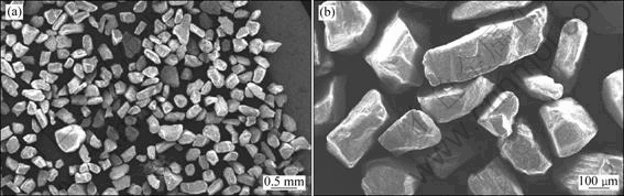
Fig.1 SEM images of quartz silica sand used as erodent

Fig.2 Schematics of erosion tester: 1��Disc; 2��Sample holder; 3��Sample; 4��Slurry media; 5��Double wall container; 6��Spindle; 7��Driving motor; 8��Column; 9��Machine base

Fig.3 3D view of erosion tester pot: 1��Tank; 2��Spindle; 3��Slurry media; 4��Disc; 5��Samples at different angles; 6��Sample holder/clamp
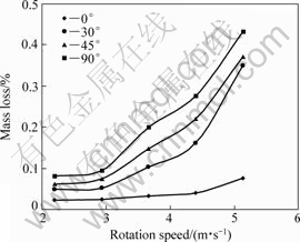
Fig.4 Plots of rotation speed vs mass loss
specimen under each test condition. The minimum wear loss was found in the case of specimen placed at 0�� position, while the maximum was obtained at 90��. Difference in the wear rates of the specimen at different angles was less at lower speed as compared with that at higher speed. There is a significant difference in the wear rate of the specimen positioned at 0�� and those positioned at higher angles (30��, 45�� and 90��) tested at maximum rotation speed of 5.13 m/s. The wear rate of specimen positioned at 0o was found to be in the range of (1-5)��10-12 m3/m, whereas, the wear rate of the other samples was found to be in the range from 20��10-12 to 25��10-12 m3/m at higher speed.
There is an insignificant increase in the wear of the specimen rotated at 2.20 and 2.93 m/s at all angles. Thereafter, wear rate increased exponentially with rotating speeds for the specimen positioned at 30��, 45�� and 90��. Effect of increased rotating speed is minimum in the case of specimen positioned at 0�� with respect to rotating direction.
3.2 Worn surface
SEM micrographs of the original surface of the specimen and the surface exposed to the slurry at 0�� and 2.93 m/s are shown in Fig.5. Fig.5(a) indicates the polishing mark on the surface (shown by arrow). Some irregularities should also be noticed (marked ��A��) on the surface. Identical surface is observed on the specimen subjected to the test at 0�� and 2.93 m/s as shown in Fig.5(b). Damaged area (marked ��B��) is observed in this case. However, the difference in topography of the surface is minimum.
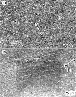
Fig.5 SEM images of original (a) and subjected to 0�� and 2.93 m/s (b) samples
Furthermore, SEM micrographs of the specimen subjected to the test with 0�� and rotation speed of 5.13 m/s are shown in Figs.6(a) and (b). It is worth noting in Fig.6(a) that the polishing mark as visualized in polished surface (Fig.5(a)) is totally absent and a ridge mark damage is observed in this case. The nature of the surface damage is seen at magnified view of the micrograph in Fig.6(b). There is crater formation (marked by single arrow) as well as tearing of the surface (marked by double arrows) as shown in Fig.6(b).
Fig.7 shows typical damaged surfaces at different rotating speeds of specimen positioned at 30��. The lower magnification micrographs of the damaged surfaces positioned at 30�� and different rotating speeds show different surface topography. Specimen surface subjected to a lower speed of 2.93 m/s presents parallel cut marks (Fig.7(a)) while the surface without scars is observed (Fig.7(b)) for the specimen subjected to higher speed (5.13 m/s). Fig.8 is the magnified view of Fig.7, which shows the cut mark and flake debris formation on the surface subjected to low rotating speed (2.93 m/s). Contrarily, smooth surface with shallow pits is observed in another case (5.13 m/s) (Fig. 8(b)). Different natures of the damage surfaces positioned at 45�� is observed in Fig.9. Low rotating speed (2.93 m/s) imparted regular cut marks (marked arrow) while high speed (5.13 m/s) induced random damaged marks (marked arrow) on the surface.
Continuous grooves on the damage surface (Fig.9(a)) are seen at lower speed (2.93 m/s) while higher speed

Fig.6 SEM images of worn surfaces (0�� and 5.13 m/s) at different magnifications
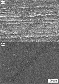
Fig.7 SEM images of worm surfaces subjected to 30�� at speed of 2.93 m/s (a) and 5.13 m/s (b)
(5.13 m/s) gives rise to random damage mark (Fig. 9(b)). Finally, surfaces positioned at 90�� at different speeds of impingement (2.93 and 5.13 m/s) show identical damage pattern (Fig.10). Large crater formation is observed in both cases. Figs.10(a) and (b) show the microstructure of surface at low and high speeds, respectively, which reveals that the amount of damaged points is higher in the case of low speed as compared with that subjected to a higher speed.

Fig.8 SEM images of worm surfaces subjected to 30�� of 2.93 m/s (a) and 5.13 m/s (b)

Fig.9 SEM images of surfaces subjected to 45�� at speeds of 2.93 m/s (a) and 5.13 m/s (b)

Fig.10 SEM images of worm surfaces subjected 90�� and at speed of 2.93 m/s (a) and 5.13 m/s (b)
4 Discussion
Erosive wear occurs when the impingement of hard particles flows in a fluid stream at high velocity. The kinetic energy of the moving particles is mainly responsible for the loss of material. The impingement attack is either by solid or by liquid media. Erosion is a complex process in which three co-existing phases, namely conveying fluid, solid particles and the metallic surface interact in many ways. Major factors effecting erosive wear rate are 1) the angle of impingement; 2) the hardness, shape and size of erosive particles; 3) the striking speed of the fluid and 4) the toughness and hardness of the eroding component. Velocity ��u�� of the particle has a significant influence upon the erosion volume loss ��V��[12] as
V=kun
where k is a constant; n is the velocity exponent generally in a range of 2-4. For a given particle velocity, n is generally found to increase as the impingement angle increases. In the present case, the values of n are 1.3, 2.3, 2.3 and 2 for the slope for 0��, 30��, 45�� and 90�� curves, respectively. In general, ductile materials exhibit peak erosion loss at low (shallow) angles, and the erosion is minimum at normal angle[13]. Contrary to this finding, erosion is maximum at normal angle in the present case (Fig.4). The main factor responsible for the increased wear with increasing impingement angle is the method of creating interaction between erodent particles and the surface. In earlier cases, erodent directly hit the surface at a particular angle[13]. However, in the present case, specimens are fitted to the disc at different angles with respect to the slurry rotation. They are hit by the erodent particles at various angles as rotating along the slurry specimen at a particular speed. Both specimens and erodent are moving in the same direction. Erosion particles would only tend to slide over the specimen surface at a lower angle without effectively hitting it, resulting in a very low wear rate (Fig.4). As the specimen angle increases, the impact of hitting increases. At a normal angle, the impingement reaches maximum as there is thorough interaction between the erodent and surface. A total kinetic energy of erodent is exhausted in crater formation. Due to the large difference in the hardness of erodent and specimen surface, crater would be easily created on the surface. Therefore, wear loss increases with increasing angle of erodent particles attacked on the surfaces, due to the high impact pressure, the material is removed. Presence of slurry helps in the removal of material from crater, angularity of erodent supports the crater formation. FINNIE[14] proposed a model of a rigid grain cut into a ductile metal, which provided an outline on how the material got swept away by the tip of particle when a polyhedral grain hit the surface. In brief, at a lower impingement angle, the tendency of erosive particles towards deflection from the surface becomes prominent[15-16], which is revealed by the groove formation on the surface (Fig.7(a)). Tendency of crater formation is high when the attack angle is high, as in the case of 90�� impingement angle (Fig.10).
A higher erosion wear rate at higher rotation speed (Fig.4) is caused by the severe damage of the surface. The erosive particles at higher velocity were associated with more kinetic energy, causing severe impingement on the specimen surface[17-20]. At a particular angle, the morphology of the wear surface is entirely different at different speeds. At lower speed of 2.93 m/s, the surface exhibited continuous cut grooves; while higher speed induced smooth surface (Figs.7(a) and (b)). It was envisaged that due to longer period of interaction and the cut action of particles, continuous grooves were generated. While at higher speed, scooped materials were rapidly removed by the impact of the particles, which resulted in smooth surface and high erosion loss (Fig.4). A similar characteristic of the surface was revealed for the specimens fixed at 90�� (Figs.10(a) and (b)). Relatively high amount of craters i.e. damaged regions were present on the surface at a lower speed (Fig.10(a)) as compared with that of the surface at a higher speed (Fig.10(b)).
Erodent particles impinging on the surface resulted in either cut/indent or physical deformation of the surface, depending on the strength and toughness of the interacting material and operating parameters. For ductile material, the theory of erosive cutting[21] is applicable, which assumes that hard and angular particles impinging on a smooth surface at an attack angle would cut the surface. Cutting processes can be classified into two categories: 1) the particle is stopped during its scooping action at a certain depth as its kinetic energy is exhausted; 2) the particle cuts the ductile surface and subsequently leaves it.
Emergence of the continuous grooves at lower speed is a result of 1) type of cutting (Figs.7(a) and 9(a)), while at higher speed, 2) type of cutting is applicable (Fig.6). Deformation of the surface also takes place in erosion. Considering the limitation of applicability of cutting and deformation theories with respect to the angle impact, NEILSON and GILCHRIST[22] proposed a combined theory in which the total erosion volume loss V is proposed to be partly due to the volume loss of cutting (Vc) and deformation (Vd). Thus, the total erosion volume loss may be given as
V=Vc+Vd
Plots of Vc, Vd and resultant V versus angle of impact change depend on the materials property, i.e. strength and toughness. MANN et al[23] demonstrated the usefulness of the equations[22] developed for various target materials like mild steel, stainless steel, aluminum and high-carbon high-chromium steel, but none of the results matches the present study, which infers that the method of tests is very important in deciding the performance of material. In the former case[23], jet erosion test was carried out; while in the present case, rotating pot test was carried out.
5 Conclusions
1) Erosive wear of the aluminum increases with increasing impingement angle in slurry tank type of test.
2) Increases in rotation speed of specimen lead to increasing wear rate. However, the effect is low for the specimen at 0�� with respect to the rotating motion. The wear is low, at a speed of about 3 m/s, beyond which it increases exponentially with increasing speed.
3) Wear takes place by cutting, impingement and removal of material from the surface of the specimen.
4) Low rotation speed leaves continuous scratch marks and formation of flake type debris due to longer period of interaction between the erodent and specimen surface, while the smooth surface is generated at higher rotation speed due to the high impact of erodent and immediate removal of material resulting from material damage on the surface.
Acknowledgement
The authors are indebted to AMPRI Bhopal and CSIR (Council of Scientific & Industrial Research institute) for continuing the study and allowing publish this work.
References
[1] HARNE A R. Life improvement of thermal power station component: A war against wear [C]//Workshop on Wear and Erosion of Materials in Thermal Power Station. CPRI, Bangalore, 1989.
[2] SAVASKAN T, MURPHY S. Mechanical properties and lubricated wear of Zn-25Al-based alloys [J]. Wear, 1987, 116: 211-224.
[3] PRASAD B K, DAS S, JHA A K, MODI O P, DASGUPTA R, YEGNESWARAN A H. Factors controlling the abrasive wear response of a zinc-based alloy silicon carbide particle composite [J]. Composites A, 1997, 28: 301-308.
[4] JHA A K, GACHAKE A, PRASAD B K, DASGUPATA R, SINGH M, YEGNESWARAN A H. High stress abrasive wear behavior of some hard faced surfaces produced by thermal spray [J]. Journal of Materials Engineering and Performance, 2002, 11(1): 37-45.
[5] SANJAY K, MONDAL D P, JHA A K. Effect of microstructure and chemical composition of hard facing alloy on abrasive wear behavior [J]. Journal of Materials Engineering and Performance, 2002, 9(6): 649-655.
[6] FINNIE I, NATESAN K. The mechanism of erosion wear in ductile material: Corrosion behaviour of materials [J]. TMS-AIME, 1980: 118-126.
[7] TU J P, PAN J, MATSUMURA N, FUKUNAGA N. The solid particle erosion behavior of Al18B4O33 whisker-reinforced AC4C Al alloy matrix composites [J]. Wear, 1981, 223: 22-30.
[8] ZHU W, MAO Z Y. Wear of material [C]// LUDEMA K C ed. Proceeding of Conference Wear of Material. ASME, 1987: 787.
[9] DESALE R G, BHUPENDRA K, GANDHI S C. Improvement in the design of a pot tester to simulate erosion wear due to solid-liquid mixture [J]. Wear, 2005, 259: 96-202.
[10] THROHE H M H, XIE Y, YICK S K. A new coriolis slurry erosion tester design for improved slurry dynamics [J]. Wear, 2003, 255: 170-180.
[11] KOSEL T H, SCATTERGOOD R O, TURNER A P L. [C]// LUDEMA K C ed. Proceeding of Conference Wear of Material. ASME, 1979: 192-204.
[12] KRISHNAMOORTHY P R, SEETHARAMU S, SAMPATHUKUMARAN P. Wear and erosion: Basic concept [C]//Proceeding of Workshop on Wear and Erosion of Materials in Thermal Power Station. CPRI, Bangalore, 1989: 7-8.
[13] CHEN L H, LIOU J W, LIU T S. SiO2 particle erosion of A356.2 aluminum alloy and the related microstructural changes [J]. Wear, 1997, 211: 169-176.
[14] FINNIE I. Erosion of surfaces by solid particles [J]. Wear, 1960, 3: 87-103.
[15] DASGUPTA R, PRASAD B K, JHA A K, MODI O P, DAS S, YEGNESHARAN A H. Slurry erosive wear characteristics of a hard faced steel: Effect of experimental parameters [J]. Wear, 1997, 213: 41-46.
[16] DASGUPTA R, PRASAD B K, JHA A K, MODI O P, DAS S, YEGNESHWARAN A H. Effect of sand concentration on slurry erosion of steels [J]. Mater Trans JIM, 1998, 39: 185-1190.
[17] TURENNE S, SIMARD D, FISAT M. Influence of structural parameters on the slurry erosion resistance of squeegee-cast metal matrix composites [J]. Wear, 1991, 149: 187-197.
[18] SRINIVASAN S, SCATTERGOOD R O, WARREN R. Erosion of fiber reinforced Ai-4 pet Cu composites [J]. Metallurgical and Materials Transactions A, 1988, 19: 1785-1793.
[19] WANG B Q, LUER K. The erosion-oxidation behavior of HVOF Cr3C2-NiCr cermet coating [J]. Wear, 1994, 174: 177-185.
[20] DAS S, MONDAL D P, MODI O P, DASGUPTA R. Influence of experimental parameters on the erosive-corrosive wear of Al-SiC particle composite [J]. Wear, 1999, 231: 195-205.
[21] FINNIE I. The mechanism of erosion of ductile metals [C]//Proc 3rd US Nat Congress of Applied Mechanics, 1958: 527-532.
[22] NEILSON J H, GILCHRIST A. Erosion by a stream of solid particles [J]. Wear, 1968, 11: 111-122.
[23] MANN B S, AULAKH R H, SHERVE S, RAO S V K, GHUSE. An experimental study to predict erosion damage of metallic, ceramic and cement materials due to impingement of particles [J]. BHEL Journal, 1986, 7(1).
����Ƕ�����ת�ٶȶ�����ʴ��Ϊ��Ӱ��
A. K. JHA, R. BATHAM, M. AHMED, A. K. MAJUMDER, O. P. MODI, S. CHATURVEDI, A. K. GUPTA
Advanced Materials and Processes Research Institute, Bhopal-462026, India
ժ Ҫ������ҵ������¶��һ��Ũ�ȵ��ཬ�У���Ʒ�Բ�ͬ�ĽǶȹ̶������ڲ�ͬ�ٶ�����ת��ͨ��������ʧ��������Ʒ��ĥ���ʡ����������������Ƕ�С��90��ʱ����Ʒ��ĥ���������Ƕȵ����Ӷ����ӡ��봫ͳ����ʶ��ͬ���������ĥ���ʳ����ڳ����Ϊ90�㣬�����dz����ڳ����45�㡣��ת�ٶȵ����ӽ�����ĥ���ʳ�ָ�����ӡ���һ�����ĥ�����Ľ������һ�¡�
�ؼ��ʣ������ཬ��ʴ�������ĥ��
Corresponding author: M. AHMED; E-mail: mahmed2@rediffmail.com
DOI: 10.1016/S1003-6326(11)60674-2
