

J. Cent. South Univ. (2019) 26: 2554-2568
DOI: https://doi.org/10.1007/s11771-019-4194-4

Effect of crack-closure treatment on fatigue durability of cracked rib-to-deck welded joints in steel bridge decks
WANG Qiu-dong(���ﶫ), JI Bo-hai(������), FU Zhong-qiu(������), YE Zhi(Ҷ֦)
College of Civil and Transportation Engineering, Hohai University, Nanjing 210098, China
 Central South University Press and Springer-Verlag GmbH Germany, part of Springer Nature 2019
Abstract:
To evaluate the effect of treating long cracks with the impact crack-closure retrofit (ICR) technique, three rib-to-deck welded specimens with a crack length of about 100 mm were tested. The metallographic structure, crack section, crack propagation life, and stress variation were analyzed. Finite-element models were also developed, and some optimal values of certain parameters are suggested according to the simulated results. The results show that new crack sources are generated on both sides of the ICR-treated region because of the stress distribution. The fatigue lives of cracked specimens with long cracks are significantly improved by the technique. Considerable residual compressive stress is also induced, and so it is suggested that the optimal impact angle to be applied to real bridges should be 70��. The stress at the weld root is distributed uniformly with the crack closed, and the optimal crack-closure depth is 4 mm. To evaluate the effect of different crack-closure depths in tests, it is recommended that a hot-spot stress method which is extrapolated by three reference points should be adopted.
Key words:
Cite this article as:
WANG Qiu-dong, JI Bo-hai, FU Zhong-qiu, YE Zhi. Effect of crack-closure treatment on fatigue durability of cracked rib-to-deck welded joints in steel bridge decks [J]. Journal of Central South University, 2019, 26(9): 2554-2568.
DOI:https://dx.doi.org/https://doi.org/10.1007/s11771-019-4194-41 Introduction
Orthotropic steel bridge decks (OSBDs) have been widely used in long-span cable-supported bridges because of their light weight, high strength, excellent wind-resistant stability, and other advantages [1, 2]. However, the structure of an OSBD is complex and the main components are welded to each other, which leads to short influence lines and considerable residual stress in the welds [3]. Therefore, the welds are susceptible to fatigue cracking under cyclic traffic loads, including extremely low-cyclic loads [4]. As an example, fatigue cracks were detected in Humen Bridge in China after it had been in service for only about 5 years [5]. There are many fatigable structural details in OSBDs, such as the rib-to-deck welds, butt welds of U-shaped ribs, and diaphragm-to-rib welds. Crack propagation is obviously bad for the structural safety and durability of the bridge. With respect to rib-to-deck welds, pavement cracking and deck rusting will be further caused once fatigue cracks start to penetrate the deck [6]. Therefore, effective measures need to be taken immediately to strengthen or repair cracked components.
The so-called ��impact crack-closure retrofit (ICR) technique�� was recently developed to retrospectively address the problem of cracks [7]. The method shares the same fundamental aims as air-hammer peening (AHP), that is, residual compressive stress is induced in the treated region so that the effective tensile stress under fatigue loading is decreased therein [8, 9]. Crack propagation is significantly delayed if the depth of the influence of the residual compressive stress exceeds the crack depth [10]. Compared to AHP, the ICR technique employs a much higher working air pressure (enhanced about 2�C3 times). This means that it creates a higher impact energy and a deeper zone of influence of the residual compressive stress. As ICR treatment is conducted on the surface of the structure, no damage is caused (unlike other common repairing methods such as drilling stop-holes [11] and re-welding [12]). Furthermore, the ICR technique has the advantages of being inexpensive, having good portability, and having a simple mode of operation. Thus, it has a broad application foreground as the technique could be applied to the complex working conditions in real bridges.
Some investigations have already been carried out relating to the mechanism and implementation effect of ICR treatment. Obvious plastic deformation zones are generated in ICR-treated surfaces and cracks become closed [7, 13]. However, related tests have been conducted using magnifying glasses, while the changes in the microstructure of ICR-treated surface layers are still unknown. Some research has revealed that AHP has a positive repairing effect on short cracks only [8, 10]. However, long cracks (commonly found in real bridges) might be arrested by ICR treatment as the ICR technique has a much higher impact energy than AHP. Even though extensive tests have been conducted to evaluate the repairing effect of the ICR technique, most of the cracks tested were no more than 50 mm in length [7, 9, 13�C15]. Therefore, additional tests are needed to evaluate the retrofit effect of the ICR technique on cracked specimens with longer cracks.
Both microhardness and residual stress tests have been conducted to analyze the local stress variation after ICR treatment has been applied to rib-to-deck welded specimens [16]. However, the crack-propagation patterns arising post ICR treatment were not analyzed in this work. Thus, the remaining fatigue life of the cracked specimens remains unknown. Even though the ICR technique has been tentatively applied to real steel bridges [15], current usage still depends on experience and relevant operational requirements. To make the technique more effective and reliable, therefore, some relevant operating parameters need to be determined (e.g. optimal impact angle and crack-closure depth).
In this paper, rib-to-deck welded specimens with long cracks (about 100 mm) were adopted to conduct ICR treatment and subsequent fatigue tests. The crack propagation sections, fatigue lives, and stress variations were analyzed to evaluate the effect of ICR treatment on the fatigue durability of the specimens. Different finite-element (FE) models were also constructed to analyze the residual stress variation and stress distribution of the welds to help interpret the test results. Subsequently, recommended optimal operating parameters, including impact angle and crack-closure depth, could be derived according to the simulated results.
2 Experimental details
2.1 Specimens
In steel bridge decks, rib-to-deck welded joints are susceptible to fatigue cracking because of local out-of-plane transverse deformations caused by the traffic load. For this work, rib-to-deck welded specimens were manufactured to simulate such fatigue. For specimens with open ribs, the stress characteristics and fatigue durability were demonstrated to be similar with that of specimens with closed ribs [17]. For ease of conducting crack-closure treatment and detecting fatigue cracks during test, specimens with open ribs were adopted here. The geometry and size of the specimens were chosen to be the same as those used in real steel bridge decks (Figure 1). There are eight bolt holes on the left side of the weld to fix the specimen to the test-bed, and four on the right side to bolt the fatigue test machine to the specimen.
Bridge steel of type Q345qD was adopted to manufacture the specimens, the mechanical properties and chemical composition of which are shown in Table 1. All the specimens were welded using CO2 gas metal arc welding technology. The Chinese Codes Welding Electrodes and Rods for Gas Shielding Arc Welding of Carbon and Low Alloy Steel (GB/T 8110-2008) [18] was consulted during the welding process.
To evaluate the effect of the repairing method, three cracked specimens were adopted (labeled S-ICR-1, S-ICR-2, and S-ICR-3). Fatigue cracks in these specimens were obtained using fatigue tests formerly conducted by our group (all were located at the weld root). The lengths of the cracks in S-ICR-1, S-ICR-2, and S-ICR-3 were 118, 104, and 94 mm, respectively.
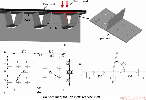
Figure 1 Specimen design and main geometric sizes (dimensions in mm):
Table 1 Mechanical properties and chemical composition of Q345qD material
2.2 Repair process
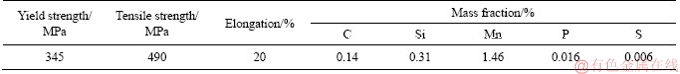
The ICR technique was adopted to repair the cracked specimens. The equipment used in the treatment process is comprised of a chisel, a pneumatic tool, and an air compressor (Figure 2). The chisel tip was burnished to a flat surface measuring 4 mm��5 mm in the shape of a rectangle with rounded corners. The frequency of the pneumatic tool was 90 Hz. The air compressor, with a tank capacity of 12 L, was used as the energy source for the pneumatic tool. During the treatment process, the air pressure of the air compressor was maintained at 0.8 MPa.
As the fatigue cracks were all located at the weld root, it was difficult to carry out the treatment due to the limitations of the operating space. For ease of operation, therefore, two thirds of the rib was cut off and removed (see Figure 3). As the upper parts of the ribs are free, it can be assumed that cutting off these parts of the ribs has no obvious effect on the stress distributions at the welds.
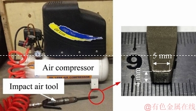
Figure 2 Devices used for ICR treatment
The specimens were fixed to the test-bed, and the fatigue cracks retrofitted using the ICR technique without applying any load. To close the crack completely, an additional length of 10 mm was set over the crack tip. The angle between the chisel and the deck was about 50��. A magnifier was used to observe the crack, and the ICR process was deemed to be finished when the crack opening was barely visible. The fatigue cracks in specimens S-ICR-1 and S-ICR-2 were fully retrofitted using the ICR treatment (Figure 4(a)).
Figure 3 Specimen with 2/3 rib cut off
With specimen S-ICR-3, however, only half of the crack was retrofitted �� the other half was left in its original state (Figure 4(b)). After ICR treatment, sections A�CA and B�CB of S-ICR-3 were sampled and metallographic tests were conducted subsequently. Figure 5 shows a photograph of the weld root profile at a magnification of 50��. It is clear from the photograph that an obvious, plastically-deformed area is generated in the material by the ICR procedure. Furthermore, the maximum compression depth is about 0.41 mm.
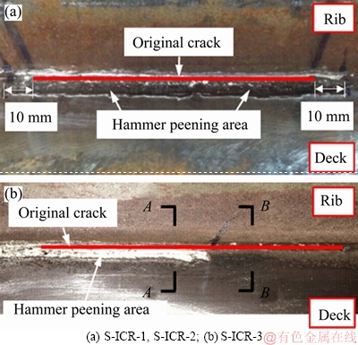
Figure 4 ICR treated surface:
2.3 Fatigue retesting
After ICR treatment, specimens S-ICR-1 and S-ICR-2 were tested again to reevaluate their fatigue properties. The specimens were bolted to the fatigue test machine (Figure 6) and a bending-type load was generated by the rotation of an eccentric block inside the testing machine. As a result, the specimens were cyclically subjected to a sinusoidal stress with a stress ratio of R=-1. In the previous fatigue tests on S-ICR-1 and S-ICR-2, the test machine was set to use frequencies of 15.3 and 15.7 Hz, respectively. Thus, the same frequencies were set for the retests (i.e., 15.3 Hz for S-ICR-1) to make the tests comparable.
To make the attachment of strain gauges easier, two positions on either side of the ICR-treated area were selected. According to Ref. [19], the stress away from the edge of the specimen varied little. Figure 7 shows the schematic curve of the stress perpendicular to the weld line (sy). Each strain gauge was placed 10 mm away from the edge of the ICR-treated area and 5 mm away from the weld root, so that the measured stress could be compared with that in previous fatigue tests. During the fatigue tests, a rust agent was regularly sprayed onto the weld root to allow the crack length to be measured. Copious amounts of microscopic bubbles are generated if the crack propagates beneath the oil layer, and thus the crack tip could be marked. A dynamic measuring system was adopted to collect the strain data during the fatigue tests.
3 Effect on residual stress
3.1 Crack-closure depth
The crack surfaces were closed by the ICR treatment according to Figure 4, which was also found in Ref. [20], but the closure depth of the cracks was not immediately apparent. As the section A�CA was cut using an abrasive disc cutter, the appearance of the closed crack was likely to change considerably due to the effect of friction. Considering that the crack closure depth was measured for qualitative analysis here, it was appropriate to replace the sample with section A�CA with other specimens with cracks. It was noted that the ideal crack is not needed. The reason is that the crack closure depth is related to the plastic deformation induced by crack-closure treatment, which has no connection with the geometric sizes of cracks. Thus, a rectangular steel bar (also made of Q345qD-type material) with an artificial crack was adopted for study. The crack was cut using a wire electric discharge machine (WEDM) and had a depth of 7 mm and width of 0.1 mm. Figure 8a shows the appearance of both the steel bar and the crack. Two further steel bars with the same geometric sizes were placed on either side of the specimen to help make the peening of the edges easier. The crack opening was photographed before and after ICR treatment at a magnification of 50��. Figure 8(b) shows the side view of the original crack and Figure 8(c) shows the equivalent view after ICR treatment. Thus, it can be seen that the treatment closed the crack to a depth of up to 1.5 mm from the surface.
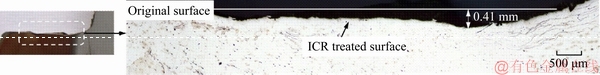
Figure 5 Photograph of plastically deformed area
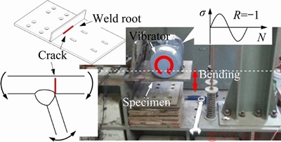
Figure 6 Fatigue testing treated specimens
3.2 Change in microstructure
The sections A�CA and B�CB in S-ICR-3 were polished using papers ranging in coarseness from 200 to 2000 grit. Thereafter, a 4 vol% nitric acid alcohol solution was used to corrode the polished surface for 5�C10 s. Then, the samples were washed in water and immediately wiped with alcohol.
Figure 9 shows the metallographic structures observed along sections A�CA and B�CB (at a magnification of 500��). Figure 9(a) shows the typical microstructure of hot-rolled steel, with ferrite and pearlite uniformly distributed throughout. However, in the ICR-treated surface layer (Figure 9(b)), both the ferrite and pearlite can be seen to be compressed. Compression makes the microstructure much more compact so that minor defects are eliminated.
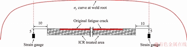
Figure 7 Arrangement of strain gauges used (dimensions in mm)

Figure 8 Crack-closure depth:

Figure 9 Comparison of microstructures:
Based on the deformation compatibility conditions, an elastic deformation zone exists between the plastic deformation zone and parent metal. The elastic deformation zone is irrecoverable because of the restraints induced by plastic deformation. As a result, residual stress is induced. It is believed that residual compressive stress is induced in the ICR-treated surface layer, which is beneficial to the mechanical behavior of the welded joints.
3.3 Analytical model
ANSYS software was adopted to develop a finite-element model (FEM) to investigate the residual stress distribution induced by the ICR treatment (Figure 10). Considering that the hardness of the chisel was much greater than that of the metal, the ICR process was simplified to a contact problem. In our experiments, the frequency of the pneumatic tool was 90 Hz. Because of the variable velocities and high accelerations involved in the ICR process, it is very difficult to simulate the ICR process accurately. Therefore, displacement- controlled loading was adopted here instead of force-controlled loading. In this model, the rigid displacement of the chisel is set to 0.41 mm, which is consistent with the maximum depth of the plastic deformation area seen in the tests.
In view of the limited range of distribution of the residual stress, a local specimen was modeled in order to save time. A spherical chisel of radius 2 mm was simulated in this model. The crack was simplified as a notch, like the one cut using WEDM, and the notch measured 40 mm long, 0.1 mm wide, and 7 mm deep. The geometric size of the model is illustrated in Figures 10 and 11. SOLID185-type elements were used to simulate the specimen and the chisel and the FEM was meshed with a refined mesh size of 0.5 mm. A bilinear kinematic hardening model with a yield strength of 345 MPa and tangent modulus of 0, was used. Element types TARGE170 and CONTA174 were adopted for the surface of the chisel and weld, respectively. To keep boundary conditions the same, nodes on the four side surfaces and top surface of the rib were fixed. The angle between the chisel and deck was 50��(i.e., the same as that used experimentally). The process of ICR in the model was divided into two steps: the pressing and lifting of the chisel. The whole process was completed in 0.01 s with each step taking 0.005 s.
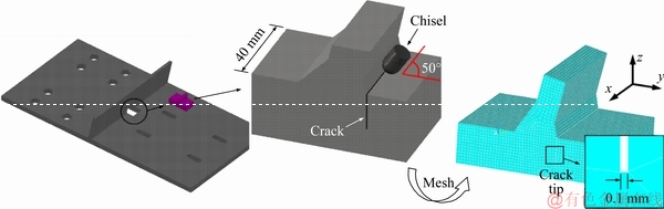
Figure 10 Finite-element model employed
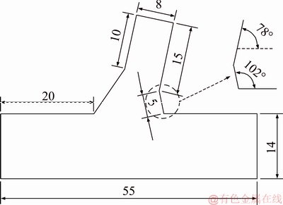
Figure 11 Geometric size of model (dimensions in mm)
3.4 Plastic deformation
Considerable plastic deformation occurs during ICR treatment. The vertical and horizontal displacements corresponding to the finished state of the chisel��s pressing and lifting operations were both plotted (Figure 12). Figure 12(a) shows the surface displacement perpendicular to the weld. The two displacement curves overlap well, which indicates that the deformation generated by the pressing action of the chisel is almost plastic. The maximum depth of the plastic deformation zone can be seen to be about 0.407 mm. Also, there is a small upper displacement of the surface around 3 mm away from the weld, which indicates the formation of a slight bulge near the edge of the ICR-treated area.
The horizontal displacement along the outside of the crack profile was plotted in Figure 12(b). The maximum horizontal displacement of 0.275 mm can be seen to be located at the surface. As the depth increases, the absolute value of the horizontal displacement decreases almost uniformly, and becomes zero at a depth of 3 mm. This reveals the limited range of influence of the plastic deformation induced by the ICR treatment. According to Figure 12(b), the absolute value of horizontal displacement becomes 0.1 mm at a depth of 1.6 mm. This indicates that the crack-closure depth in the FEM is 1.6 mm, which agrees well with the test result (1.5 mm). And the closure depth was similar with that induced by portable pneumatic needle-peening treatment (PPP treatment) [21]. It demonstrates that the simplifications made to the FEM are acceptable. And it is also acceptable to replace the samples of section A-A with specimens with artificial cracks.
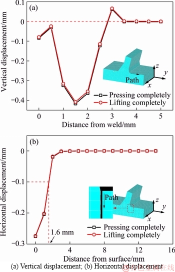
Figure 12 Displacement variation in ICR-treated zone:
3.5 Residual stress
Residual compressive stress is beneficial to the fatigue properties of the rib-to-deck weld, especially the component of the residual compressive stress perpendicular to the weld (sy,r). Figure 13 presents curves showing how sy,r varies at different depths below the surface of the metal. According to this figure, the stress curves all approach zero at positions 9 mm away from the weld. This suggests that the horizontal range of influence of the residual stress is 9 mm. The maximum values in the sy,r curves increase at first and then decrease along the deck depth. The maximum residual compressive stress (325 MPa) occurred 1 mm under the surface.
Residual tensile stress was found at depths of 1.5 to 2 mm. This indicates that both plastic and elastic deformation were generated by the ICR treatment, which is in agreement with the deformation compatibility condition.
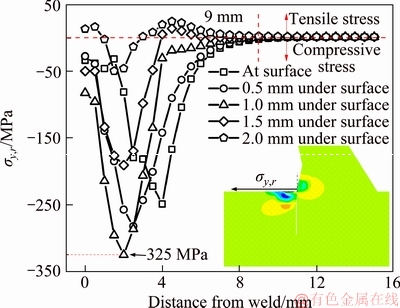
Figure 13 Distribution of residual stress
3.6 Effect of impact angle
With regard to the above model (meshed with a mesh size of 0.5 mm), the whole calculating process lasted for about 8 h using a Dell workstation. In order to save time, a mesh size of 1 mm was used in the following series of calculations. The angle of impact (q) was varied from 30�� to 90�� using 10�� increments, and the sy,r distribution calculated 1 mm below the surface of the metal was plotted in Figure 14.
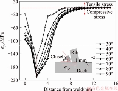
Figure 14 Effect of impact angle on distribution of stress sy,r
Comparing Figures 13 and 14, it can be seen that the stress values decrease as the mesh size is increased. However, the variation in the stress distribution remains the same. Figure 14 shows that the relevant value of residual compressive stress increases at first as the impact angle is increased and then tends to remain almost unchanged. The threshold for this behavior change is about 70�� (as the sy,r curves corresponding to the 70��, 80��, and 90�� results are almost overlapped). As far as real bridges are concerned, maintenance workers will carry out the ICR treatment overhead on a ladder. It would be very difficult to retrofit the cracks using an impact angle of 90��. Therefore, an impact angle of 70�� is recommended.
4 Effect on crack propagation
4.1 Crack propagation section
The original cracks in S-ICR-1 and S-ICR-2 were closed after ICR processing. During the subsequent fatigue testing process, the crack propagation patterns in the two specimens were almost the same. That is, only the tips of the closed cracks propagated again and the remaining parts remained well closed. However, two new cracks propagated on both sides of the ICR-treated areas. Figure 15 shows the crack section of specimen S-ICR-1. A hardened surface layer is present in the section, as can be seen in Figure 15(a), which also reveals that the central part of the original crack remained closed during the entire fatigue loading process.
Figure 15(a) also indicates that both the original and new crack tips on the opposite sides of the original crack propagated outwards in the directions shown by the red arrows. There are obvious junctions between the original and new crack sections which are just below the edges of the ICR-treated surface. In the newly cracked sections, the curvature of the crack front on the nearside of the junction is greater than that on the other side. This shows that the hardened surface layer and residual compressive stress limits the propagation of the new cracks towards the ICR-treated area. If the specimen had not been cut and tested again, we can assume that the original and new crack sections would probably have merged together.
4.2 Crack propagation rate
Figure 16 presents curves showing how the original and new cracks propagated (no data was collected for a new crack on the right in S-ICR-1 as the phenomenon was not obvious in this specimen). According to Figure 16, an obvious inflection point exists between the original cracks�� propagation curve before and after ICR treatment (segments AB and BC, respectively) which indicates a significantly decreased rate of crack propagation. The probable propagation curves for the original cracks are also plotted in Figure 16 as dotted lines based on the former test results (segments BD), as the crack propagation rate could be relatively accurately and conservatively considered to be the same as that in the previous fatigue test if the crack-closure treatment was not conducted. The angles between segments BD and BC are 45��-60��, showing that the propagation of the original cracks after ICR treatment were effectively delayed. By the time the fatigue tests were finished, the propagation lengths of the original cracks in S-ICR-1 and S-ICR-2 were about 7 and 9 mm, respectively. Compared to the original crack lengths before ICR treatment (118 and 104 mm, respectively) which were generated using similar loading cycles, it can be seen that the original cracks were almost arrested.
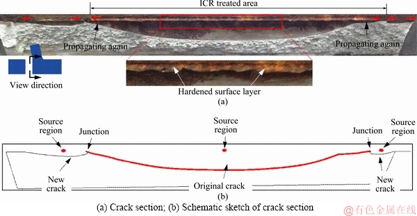
Figure 15 Crack section of S-ICR-1:
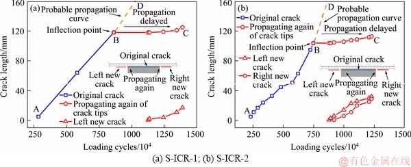
Figure 16 Crack propagation curves:
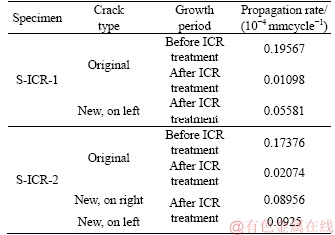
A linear fitting method was adopted to calculate the average propagation rates��the results are shown in Table 2. The results show that the average propagation rates of the original cracks in ICR-treated S-ICR-1 and S-ICR-2 are only 5.6% and 11.9% of the original rates, respectively. Thus, the crack propagation rates are dramatically reduced by the ICR treatment. The average propagation rate of the new cracks is around 40% of that of the original cracks before ICR treatment. The reason for this is that the propagation of the new cracks is limited by the hardened surface layer and residual compressive stress induced by the ICR treatment.
4.3 Crack propagation life
The average crack propagation rates in the original S-ICR-1 and S-ICR-2 specimens (i.e., before ICR processing) were 0.19567�� 10-4mm/cycle and 0.17376��10�C4mm/cycle, respectively. Assuming that if the cracked specimens were retested without ICR treatment and the original crack propagated again at the same rate, the fatigue life (in terms of number of cycles) corresponding to a certain crack length a can be calculated according to the formula.
 (1)
(1)
where Ncal is the calculated propagation life (cycles), a is the crack length (a1, a2, or a3), and  is the average propagation rate (0.19567��10-4mm/cycle and 0.17376��10-4mm/cycle for the two specimens). Herein, a1 refers to the propagation length of the original crack after ICR treatment, a2 refers to the sum of the new crack propagation lengths, and a3 is the sum of a1 and a2.
Table 2 Average crack propagation rates before and after ICR process
The test and calculated results are plotted in Figure 17. According to Figure 17, the real fatigue lives of the ICR-treated S-ICR-1 and S-ICR-2 specimens are about 5 and 1.8 times higher than the average calculated ones, respectively. This shows that the fatigue life of a cracked specimen with long cracks can be significantly improved by the ICR treatment.
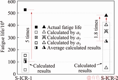
Figure 17 Comparison of fatigue lives
5 Discussion of stress variation
5.1 Test results
The frequencies used in the current fatigue tests were the same as those used in the former fatigue tests to make the results comparable. The results obtained for the variation in the stress sy in the two specimens are plotted in Figure 18. According to Ref.[19], the stress amplitudes in the two strain gauges used in this test should be similar. In the previous fatigue tests conducted by our group, a strain gauge was placed at the center of the weld root, and the stress amplitude was nearly 80 MPa at the initial loading stage. Therefore, assuming that the two strain gauges are also arranged in the same position in the current tests, the corresponding stress amplitudes should be about 80 MPa. As can be seen from Figure 18, the stress amplitudes at the initial fatigue loading stage were between 80 and 90 MPa, which are almost the same as that found in the previous fatigue tests. This shows that the mechanical proprieties of the cracked rib-to-deck welded joints were improved by the ICR treatment.
Due to the initiation and propagation of new cracks, the stress amplitudes decrease in time and significant stress distribution occurs. The stress amplitude on the right side of the ICR-treated area of specimen S-ICR-1 (��S-ICR-1-right��) decreased most slowly, as this corresponds to the minor crack propagation section shown in Figure 15(a).
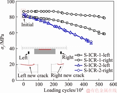
Figure 18 Stress variation at weld root
5.2 FE analysis of stress variation
Another FEM was developed using ANSYS software to calculate the stress distribution at the weld root. The size of the FEM was taken to be the same as the specimens used (Figure 19). A simplified notch was also simulated (100 mm long, 0.1 mm wide, and 8 mm deep, which is similar to the actual cracks in S-ICR-1 and S-ICR-2) as illustrated in Section 3.3. In view of the complexity of the residual stress distribution, the residual stress was not considered in the FEM. However, crack closure was simulated to a depth of 1.5 mm, which is consistent with the test results.
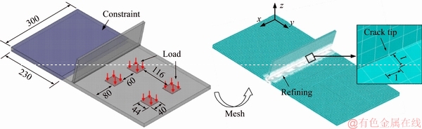
Figure 19 FEM used for stress analysis (dimensions in mm)
An elasticity analysis was carried out assuming the elastic modulus of the material to be 210 GPa and the Poisson ratio to be 0.3. SOLID185 was also adopted to simulate the specimen. The weld zone was meshed with a refined mesh size of 1 mm, while the other parts were meshed with a mesh size of 7 mm. Two transition regions were arranged between the refined and coarse regions to ensure a smooth transition. The arrangement of the transition regions is shown in Figure 20. In this diagram, Z1 refers to the refined region, and Z2 and Z3 refer to the transition regions. The boundary conditions were the same as those used in the fatigue tests, that is, the size of the confined zone was 230 mm��300 mm. The static analysis based on no-cracked rib-to-deck specimens showed that the nominal stress at weld root equaled 100 MPa when the surface loads of 0.71 N/mm2 were applied. Hence, four surface loads of 0.71 N/mm2 were applied to the model above the bolt holes of the specimen. The loading area was equal to the contact area between the fatigue test machine and specimen, as shown in Figure 19.
5.3 Stress variation at weld root
The stress calculated at the weld root and strain gauge location are plotted in Figure 21. According to Figure 21(a), the stress at the crack tip is about 400 MPa, while the maximum stress found in the ICR-treated model is about 170 MPa. Furthermore, the stress concentration region is transferred to the center of the weld. As the residual compressive stress could be about 250 MPa after ICR treatment (as shown in Figure 13), the effective tensile stress at the ICR-treated surface will be significantly decreased. Therefore, the maximum effective tensile stress will be transferred to both sides of the ICR-treated area. Thus, new cracks will be generated here in the subsequent fatigue loading process, as demonstrated by the test results.
Figure 21(b) shows the stress distribution at the strain gauge location. Fatigue cracking leads to a sharp decrease in the stress amplitude therein, while the stress amplitude is increased at the crack tip. However, the stress is distributed uniformly after ICR treatment, which indicates that the mechanical properties of the cracked specimen are recovered.
5.4 Effect of multiple cracks
For our rib-to-deck welded joints, the crack propagation behavior differed from previous test results as the original and new cracks propagated concurrently. To investigate the effect of multiple cracks on the stress distribution at the weld root,three further FEMs were developed:Model I-to simulate new cracks only,Model II-to simulate the original cracks only (including propagation after ICR treatment) and, Model III-to simulate all the cracks.
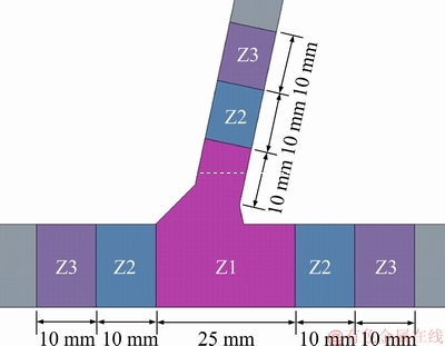
Figure 20 Arrangement of transition regions
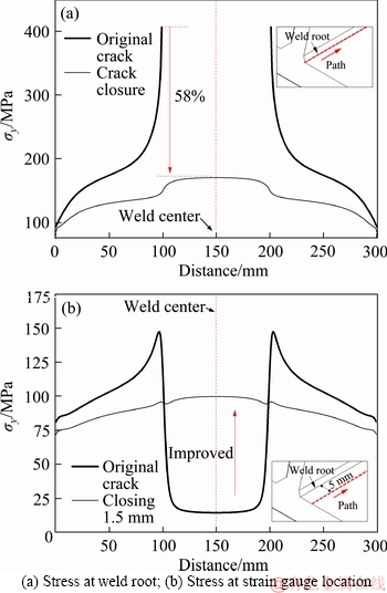
Figure 21 Results of finite-element analysis:
The lengths and positions of the cracks are shown in Figure 22. The parameters used in these FEMs are the same as those used in the previous one introduced in Section 5.2. The stress amplitudes thus calculated at the crack tips are plotted in Figure 23. According to this figure, the stress amplitudes at the crack tips (labeled symax) in models I and II are 264.5 and 267.8 MPa, respectively, which are very similar. However, with multiple cracks present at the weld root, i.e., in Model III, symax increased to 286.3 MPa. The stress amplitudes at the other crack tips are also larger. This shows that multiple cracks will propagate at a higher rate than a single crack.
However, the propagation rates of the original and new cracks after ICR treatment were found to be less than half of the value of an untreated crack (as shown in Table 2). This demonstrates that the propagation of multiple cracks has less influence when the material has received ICR treatment.
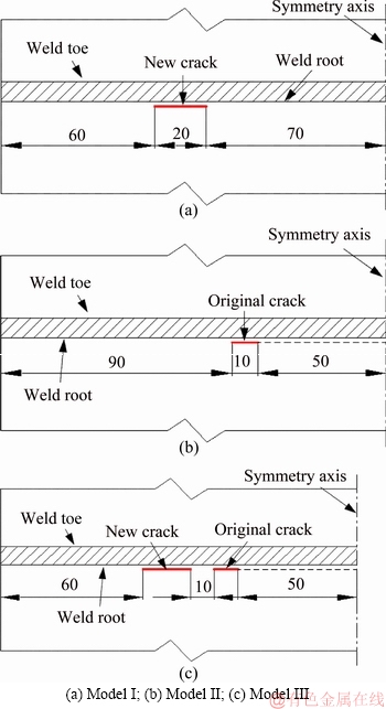
Figure 22 Different models used to consider effect of having multiple cracks present (dimensions in mm):
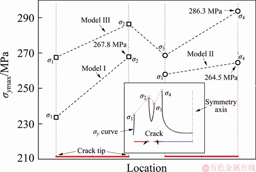
Figure 23 Effect of multiple cracks on stress distribution
Therefore, it can be speculated that the fatigue life of ICR-treated specimens will be further improved if the whole of the weld root is treated with the ICR technique.
5.5 Effect of crack-closure depth
To investigate the effect of crack-closure depth on stress distribution, additional FE models were developed with cracks with closure depths of 1, 2, 2.5, 3, 4, and 5 mm (in each case, the crack was 8 mm deep before closing). Since the crack remained closed at the initial stage of fatigue re-testing, the closed part, of which the depth equaled to the crack closure depth, was assumed to be continuous in the FE model. The calculated stress distributions at the weld root and strain gauge location are shown in Figure 24.
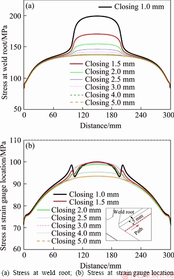
Figure 24 Effect of crack-closure depth on stress variation:
The stress at the weld root gradually decreases as the crack-closure depth increases (Figure 24(a)), while the stress at the strain gauge location changes little (Figure 24(b)). Figure 24(a) also shows that the stress curves corresponding to closure depths of 4 and 5 mm are almost merged together. As the impact energy required to achieve a closure depth of 5 mm would be larger, a crack-closure depth of 4 mm can be seen to be more acceptable.
In each of these FE models, the crack depth was set to 8 mm. To acquire a more universal impact parameter, the crack depth was transformed to 6 and 10 mm and the calculations rerun for crack-closure depths corresponding to 2, 3, 4, 5, and 6 mm. Considering that the stress at the weld root is more sensitive to the crack-closure depth, the stress perpendicular to the weld root, of which the extracting point is located at the middle of weld root line, are focused on (Figure 25). According to this figure, the variation of the stress amplitude with crack-closure depth shows the same trend irrespective of the depth of the crack. As the crack-closure depth increases, the stress amplitude gradually decreases (as does the gradient). These results suggest that the crack depth has little effect on the optimal crack-closure depth, and so a crack-closure depth of 4 mm can be recommended in general.
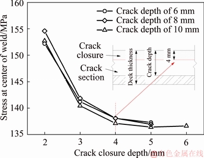
Figure 25 Effect of crack depth on optimized crack-closure depth
5.6 Comparison of stress measuring methods
In light of Figure 24(b), it is apparent that the effect of different crack-closure depths cannot be convincingly compared using the nominal stress variation measured in the tests. Therefore, a more effective method of stress measurement is needed in such experiments. Compared to methods based on nominal stress, those based on hot-spot stress are a more precise option [22]. Thus, hot-spot stresses extrapolated using two reference points (shs,2) and three reference points (shs,3) are considered here. Figure 26 shows how the strain gauges need to be arranged to facilitate the measurement of these stresses. The hot-spot stresses are then calculated using the expressions:
 (2)
(2)
 (3)
(3)
Figure 27 shows a comparison of the results. According to this figure, the (two and three reference point) hot-spot stress gradually decreases as the crack-closure depth increases. This trend is very similar to that occurring in the stress at the weld root (the nominal stress can also be seen to be less responsive). However, the gradient of the shs,3 curve changes more than that of the shs,2 curve. Therefore, considering the experimental error in the measurement process, we recommend that the hot-spot stress derived by extrapolating three reference points is adopted.
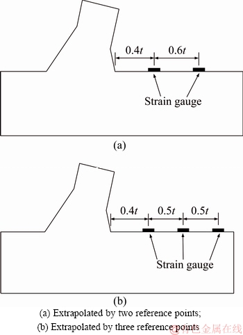
Figure 26 Arrangement of strain gauges used to measure hot-spot stress:
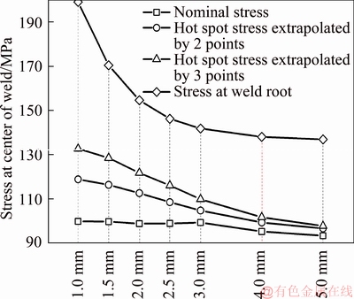
Figure 27 Comparison of hot-spot stress, nominal stress, and stress at weld root
6 Conclusions
1) During fatigue tests performed after ICR treatment, two new cracks were initiated on both sides of the ICR-treated area of the rib-to-deck specimens but the retrofitted crack remained very well closed, which demonstrates an obvious stress distribution. It is recommended that both the ICR-treated area and adjacent regions be regularly checked after the ICR techniques have been applied to real bridges.
2) Even though multiple collinear cracks propagated at the same time, the relative average propagation rate was less than half of the one prior to ICR treatment. The fatigue lives of the ICR-treated specimens were more than doubled. The results clearly reveal that the fatigue properties of the cracked rib-to-deck specimens could be effectively improved using the ICR technique.
3) The metallographic structure of the surface layer becomes more compact after ICR treatment, which has a beneficial effect on the weld��s mechanical properties. Increasing the impact angle resulted in increased maximum compressive residual stress at first. After this initial increase, however, it then remained almost unchanged. An impact angle of 70�� was found to be optimal.
4) The weld stress was distributed uniformly after the crack was closed by the ICR process. Considering the efficiency of the process (i.e., the impact energy required), a crack-closure depth of 4 mm is recommended. In addition, it is recommended that a hot-spot stress method extrapolated by three reference points should be adopted to measure the stress perpendicular to the weld.
References
[1] FU Zhong-qiu, JI Bo-hai, ZHANG Cheng-yi, LI Di. Experimental study on the fatigue performance of roof and U-rib welds of orthotropic steel bridge decks [J]. KSCE Journal of Civil Engineering, 2017(3): 1-9. DOI: 10.1007/s12205-017-1725-0.
[2] GUO Tong, LI Ai-qun, WANG Hao. Influence of ambient temperature on the fatigue damage of welded bridge decks [J]. International Journal of Fatigue, 2008, 30(6): 1092-1102. DOI: 0.1016/j.ijfatigue.2007.08.004.
[3] KAINUMA S, JEONG Y S, YANG Mu-ye, INOKUCHI S. Welding residual stress in roots between deck plate and U-rib in orthotropic steel decks [J]. Measurement, 2016, 92: 475-482. DOI: 10.1016/j.measurement.2016.06.040.
[4] GE Han-bin, KANG Lan, TSUMURA Y. Extremely low-cycle fatigue tests of thick-walled steel bridge piers [J]. Journal of Bridge Engineering, 2013, 18(9): 858-870. DOI: 10.1061/(ASCE)BE.1943-5592.0000429.
[5] JI Bo-hai, LIU Rong, CHEN Ce, MAENO H, CHEN Xiong-fei. Evaluation on root-deck fatigue of orthotropic steel bridge deck [J]. Journal of Constructional Steel Research, 2013, 90(5): 174-183. DOI: 10.1016/j.jcsr.2013. 07.036.
[6] LI Ming, SUZUKI Y, WANG Hong-chang, AOKI Y, ADACHI Y, SUGIURA K. Experimental study of asphalt surfacing influence on rib-to-deck joints considering temperature and dynamic effects [J]. Journal of Bridge Engineering, 2016, 21(11): 04016077. DOI: 10.1061/ (ASCE)BE.1943-5592.0000936.
[7] ISHIKAWA T, YAMADA K, KAKIICHI T, LI Hui. Extending fatigue life of cracked out-of-plane gusset by ICR treatment [J]. JSCE Journal of Structural and Earthquake Engineering, 2010, 66(2): 264-272. DOI: 10.2208/jsceseee. 28.21s.
[8] FISHER J W, HAUSAMMANN H, SULLIVAN M D, PENSE A W. Detection and repair of fatigue damage in welded highway bridges [R]. Washington DC: NCHRP Report 206, 1979. http://onlinepubs.trb.org/Onlinepubs/ nchrp/nchrp_rpt_206.pdf.
[9] ISHIKAWA T, SHIMIZU M, TOMO H, KAWANO H, YAMADA K. Effect of compression overload on fatigue strength improved by ICR treatment [J]. International Journal of Steel Structures, 2013, 13(1): 175-181. DOI: 10.1007/ s13296-013-1016-7.
[10] FISHER J W, ROY S. Fatigue damage in steel bridges and extending their life [J]. Advanced Steel Construction, 2015, 11(3): 250-268. DOI: 10.18057/IJASC.2015.11.3.1.
[11] FU Zhong-qiu, JI Bo-hai, XIE Shu-hui, LIU Tian-jia. Crack stop holes in steel bridge decks: Drilling method and effects [J]. Journal of Central South University, 2017, 24(10): 2372-2381. DOI: 10.1007/s11771-017-3649-8.
[12] FU Zhong-qiu, WANG Qiu-dong, JI Bo-hai, YUANZHOU Zhi-yuan. Rewelding repair effects of fatigue cracks in steel bridge deck welds [J]. Journal of Performance of Constructed Facilities, 2017, 31(6): 04017094. DOI: 10.1061/(ASCE)CF.1943-5509.0001083.
[13] YUANZHOU Zhi-yuan, JI Bo-hai, FU Zhong-qiu, GE Han-bin. Fatigue performance of cracked rib-deck welded joint retrofitted by ICR technique [J]. International Journal of Steel Structures, 2016, 16(3): 735-742. DOI: 10.1007/ s13296-015-0089-x.
[14] YAMADA K, ISHIKAWA T, KAKIICHI T. Rehabilitation and improvement of fatigue life of welded joints by ICR Treatment [J]. Advanced Steel Construction, 2015, 11(3): 294-304. DOI: 10.18057/IJASC.2015.11.3.4.
[15] YAMADA K, ISHIKAWA T, KAKIICHI T. Extending fatigue durability by closing crack surface [J]. Journal of Japan Society of Civil Engineers Ser A1, 2009, 65(4): 961-965. DOI: 10.2208/jsceja.65.961. (in Japanese)
[16] YUANZHOU Zhi-yuan, JI Bo-hai, FU Zhong-qiu, GE Han-bin. Local stress variation in welded joints by ICR treatment [J]. Journal of Constructional Steel Research, 2016, 120: 45-51. DOI: 10.1016/j.jcsr.2015.12.001.
[17] YA S, YAMADA K. Fatigue durability evaluation of trough to deck plate welded joint of orthotropic steel deck [J]. Structural Engineering/earthquake Engineering, 2008, 64(3): 603-616. DOI: 10.2208/jsceja.64.603.
[18] GB/T 8110. Welding electrodes and rods for gas shielding arc welding of carbon and low alloy steel [S]. 2008. https:// wenku.baidu.com/view/346d4c0de418964bcf84b9d528ea81c758f52e9e.html. (in Chinese)
[19] FU Zhong-qiu, JI Bo-hai, ZHANG Cheng-yi, WANG Qiu-dong. Fatigue performance of roof and U-rib weld of orthotropic steel bridge deck with different penetration rates [J]. Journal of Bridge Engineering, 2017, 22(6): 04017016. DOI: 10.1061/(ASCE)BE.1943-5592.0001036.
[20] YUANZHOU Zhi-yuan, JI Bo-hai, FU Zhong-qiu, SUN Tong. Retarding effects on crack propagation by closing crack surface using ICR treatment [J]. Journal of Constructional Steel Research, 2018, 143: 11-17. DOI: 10.1016/j.jcsr.2017.12.015.
[21] KINOSHITA K, BANNO Y, ONO Y, YAMADA S, HANDA M. Fatigue strength improvement and fatigue crack closure by portable pneumatic needle-peening treatment on welded joints [J]. International Journal of Steel Structures, 2019, 19(3): 693-703. DOI: 10.1007/s13296-018-0153-4.
[22] HOBBACHER A. Recommendations for fatigue design of welded joints and components [M]. Berlin: Springer International Publishing, 2015. DOI: 10.1007/978-3-319- 23757-2.
(Edited by HE Yun-bin)
���ĵ���
������嶥�����Ƶ����������Ч����
ժҪ��Ϊ����������������Գ����Ƶ���Ч����ѡȡ���������Ƴ��Ⱦ�Ϊ100 mm���ϵĶ�����U���Լ�����չ��������������鼰����ƣ�ͼ��أ����������۽ṹ�仯�����ƶ��桢������չ���ʡ�Ӧ�����ȡ�ͬʱ���������������Ԫģ�ͣ����ڷ����������˲��ֹؼ��ļ����������о����������ڴ������Ӧ���طֲ����ڴ�����������������µ�ƣ��Դ���������г������Լ���ƣ��������Ȼ�õ�����������ߡ���������ɲ����ɹ۵IJ���ѹӦ����Ϊȡ�����Ч������������ǶȽ���Ϊ70�㡣���ƱպϺ�Ӧ���ʲ����ȷֲ�����ѵıպ����Ϊ4 mm�������Ʊպ����Ӱ��������о��У���������������Ƶõ����ȵ�Ӧ����Ϊ����ָ�ꡣ
�ؼ��ʣ�������壻ƣ���;��ԣ��������������ƣ��������Ӧ���ֲ�
Foundation item: Projects(51478163, 51678216) supported by the National Natural Science Foundation of China; Project(2017Y09) supported by the Transport Science Research Project of Jiangsu Province, China
Received date: 2017-12-24; Accepted date: 2018-11-15
Corresponding author: JI Bo-hai, PhD, Professor; Tel: +86-25-83786832; E-mail: bhji@hhu.edu.cn; ORCID: 0000-0002-2737-6134
Abstract: To evaluate the effect of treating long cracks with the impact crack-closure retrofit (ICR) technique, three rib-to-deck welded specimens with a crack length of about 100 mm were tested. The metallographic structure, crack section, crack propagation life, and stress variation were analyzed. Finite-element models were also developed, and some optimal values of certain parameters are suggested according to the simulated results. The results show that new crack sources are generated on both sides of the ICR-treated region because of the stress distribution. The fatigue lives of cracked specimens with long cracks are significantly improved by the technique. Considerable residual compressive stress is also induced, and so it is suggested that the optimal impact angle to be applied to real bridges should be 70��. The stress at the weld root is distributed uniformly with the crack closed, and the optimal crack-closure depth is 4 mm. To evaluate the effect of different crack-closure depths in tests, it is recommended that a hot-spot stress method which is extrapolated by three reference points should be adopted.
