
J. Cent. South Univ. Technol. (2011) 18: 1304-1310
DOI: 10.1007/s11771-011-0837-9![]()
Stress and deformation due to embankment widening with different treatment techniques
WANG Hao(����)1, HUANG Xiao-ming(������)2
1. Department of Civil and Environmental Engineering, University of Illinois at Urbana-Champaign,
IL 61866, USA;
2. School of Transportation, Southeast University, Nanjing 210096, China
? Central South University Press and Springer-Verlag Berlin Heidelberg 2011
Abstract:
A two-dimensional (2-D) finite element (FE) model was developed to analyze the deformation and stress of embankment on soft ground due to widening with different treatment techniques. It is found that the embankment widening induces transverse gradient change due to differential settlements and horizontal outward movements at the shoulder of the existing embankment. Embankment widening also increases the shear stress along the slope of the existing embankment, especially at the foot of slope. The failure potential due to embankment widening may increase with the increase of widening width when the widening width is smaller than 8.5 m, but may decrease with the increase of widening width as the widening width is greater than 8.5 m. The effectiveness of four ground and embankment treatment techniques, including geosynthetic reinforcement, light-weight embankment, deep mixed columns, and separating wall were compared. The results indicate that these treatments reduce the differential settlements and improve the stability. The light-weight embankment has the most effectiveness among four treatments. By using the fly-ash backfill material in widening, the transverse gradient change decreases from 0.5%-1.3% to 0.26%-0.8% and the maximum horizontal displacement decreases from 2.76 cm to 1.44 cm.
Key words:
1 Introduction
Now, many highways are confronted with embankment and pavement widening for the purpose of increasing traffic capacity. Differential settlements may develop between and within the new and existing embankments due to widening, especially on soft soils. This could cause transverse gradient change at the pavement surface and longitudinal pavement cracking at the vicinity of the joint between the existing and new pavements [1-5].
Various treatment techniques have been reported in the literature to reduce the differential settlements due to widening, such as excavated terrace on the existing slope, staged (gapped) construction, geosynthetic reinforcement, preloading with surcharge, foundation improvement, and a combination of the above alternatives. DESCHAMPS et al [6] emphasized the importance of adequate compaction and consistent permeability of the existing and new embankment material. HAN and AKINS [7] reported using vibro-concrete columns in conjunction with geogrid layers above to support widened embankments. ALLERSMA et al [8] and MEURS et al [9] investigated the effectiveness of the gapped construction method for embankment widening using field study and centrifuge experiment. FORSMAN and UOTINEN [10] and HUANG and WANG [11] studied the effect of geosynthetic reinforcement on the differential settlements and horizontal displacements of embankments after widening. HAN et al [12] concluded that the installing columns under the widened portion and/or the connecting side slope of the existing embankment could reduce the maximum settlement, transverse gradient change, and the shear stress induced by widening of the embankments.
Although various treatment techniques have been commonly adopted in practice for widening of embankments, limited researches were conducted to compare the effectiveness of different treatments and the design guideline is still not available for widening projects. In addition, it is important to select the appropriate ground treatment technique based on the geotechnical investigation of the widening site. In this work, a numerical model is developed to analyze the responses of embankment and foundation caused by widening, including the differential settlements, horizontal displacements, and stress distributions. Four different treatment techniques were simulated in the model and their influences on the stress and deformation of the existing and new embankments after widening were compared.
2 Development of finite element model
A two-dimensional (2-D) finite element (FE) model based on Biot consolidation theory was developed to calculate the responses of embankment and foundation due to widening. The GEO SLOPE software [13] was used to develop the FE model.
2.1 Model geometry
The embankment is supposed to be infinite in the longitudinal direction and thus can be considered as plain strain condition. The schematic representation of the embankment structure is shown in Fig.1. The width of old embankment (B) is 26 m and the height (h) is 4 m. The slopes of old and new embankments are both 1:1.5. The foundation depth (H) considered in the model is 15 m and it is deep enough until no additive stress is caused in the foundation. The width of widening embankment (b) is 4, 8.5 and 12.5 m, respectively. Due to the symmetry in loading and geometry, only half of the embankment and foundation was simulated. This required imposing a boundary on the plane of symmetry in the transverse direction. Another fixed boundary was imposed at the bottom of foundation.
2.2 Loading process
Only the self-weight of new embankment was considered as the load input in the model and the vehicle load was neglected in this work. The total loading process was divided into five steps: 1) consolidation of the foundation; 2) construction of the existing embank- ment; 3) consolidation of the existing embankment; 4) construction of the new embankment; 5) consolidation of the new embankment. The stress field at the end of each consolidation step was used as the initial stress state for the following steps. The increment steps were used to simulate the layered construction of the embankment.
2.3 Material parameters
The soil was simulated with eight-node quadratic isoparametric element. Due to the complexity of the problem itself, a simplified constitutive model was used in this analysis within reasonable accuracy. Considering the fact that the stress redistribution is a key mechanism and the properties of foundation soil and embankment fill are stress dependent, a nonlinear hyperbolic elastic model subjected to the Biot consolidation theory was adopted [14-16]. The soil tangential modulus (Et) for a given stress condition is given by
 (2)
(2)
where Rf is the failure ratio defining the shape of the stress-strain curve; k is the dimensionless parameter representing elastic modulus; n is the modulus exponent governing the stress dependence of k on ��3 (range of values: 0-1); �� is the internal friction angle; c is the cohesion intercept; pa is the atmospheric pressure used for normalization of stress input; ��1 is the first principal stress; ��3 is the third principal stress.
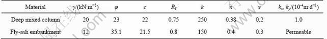
The material parameters of foundation soil and embankment fill used in the calculation were determined from the consolidated undrained triaxial tests [17], as listed in Table 1, where �� is soil volume weight; �� is Poisson ratio; kx, ky are penetration parameters. The Poisson ratios were assumed as constants: 0.3 for clay foundation and 0.35 for embankment fill, respectively.
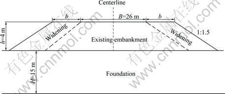
Fig.1 Schematic illustration of model geometry
Table 1 Soil Parameters of Foundation and Embankment
3 Deformation and stress of embankment due to widening
3.1 Influence of widening on deformation
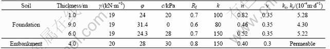
The schematic plots of the deformed mesh of the ground and embankment and the displacement vectors after widening are shown in Figs.2(a) and (b), respectively. The plots show that there is an apparent depression of new embankment into the soft ground, which causes the opposite horizontal movements of the ground soil.
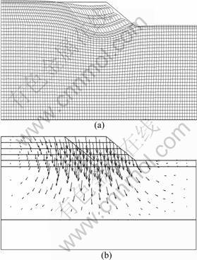
Fig.2 Schematic plots of deformations after widening for mesh (a) and displacement vectors (b)
Figure 3 compares the settlements along the surface of embankment after widening with different widening widths. It is obvious that the non-uniform settlements exist depending on the distance to the center of existing embankment. The maximum settlement is found in the region near the joint between the existing and new embankment, while the minimum settlement at the center of the existing embankment. This could result in differential settlements and transverse gradient change at pavement surface. After widening, the transverse gradient changes at the embankment surface are around 0.5%-1.3% due to differential settlements. These transverse gradients are calculated as the differential settlements divided by its corresponding distance. The maximum transverse gradient change happens in the vicinity of the joint between the existing and new embankment, because the widened portion has the greater settlement than that for the existing embankment. This suggests that the treatment techniques should be conducted under/within the joint part between the existing and new embankment to avoid possible failure or damage of roadways after widening.
Fig.3 Settlement distributions along surface of embankment
As the widening width increases, the maximum settlement increases, especially when the widening width increases from 4 to 8.5 m. However, the transverse gradient change is not significantly affected by the widening width. This is because the maximum settlement moves away from the joint toward the center of the new embankment as the widening width increases.
The horizontal displacement indicates the stability of the new embankment and ground after widening. Figure 4 compares the horizontal displacement along the surface of the embankment after widening with different widening widths. The shoulder of the existing embankment exhibits the maximum outward horizontal movement (around 2-2.7cm) away from the center. This indicates that the possible slippage surface of the new embankment after widening could be along the slope of the existing embankment. The maximum horizontal displacement increases as the widening width increases from 4 to 8.5 m, but decreases as the widening width increases from 8.5 to 12.5 m.
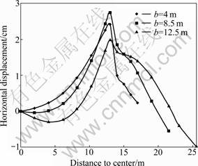
Fig.4 Horizontal displacement distributions along surface of embankment (Positive means moving away from centerline, and vice versa)
3.2 Influence of widening on stress distributions
Figures 5(a) and (b) compare the maximum shear stress contours in the embankment and ground before and after widening, respectively. It is obvious that the widening changes the distribution of shear stress in the ground and embankment. After widening, the concentration of shear stress in the embankment is located in the area along the slope of the existing embankment, especially at the foot of slope. The highest shear stress in the foundation is found under the new embankment at the bottom of soft soil.
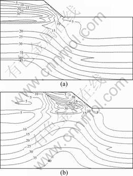
Fig.5 Maximum shear stress contours before (a) and after (b) widening (unit: kPa) (b=8.5 m)
The transverse distribution of the shear stress along the surface of the old embankment is shown in Fig.6. It is interesting to see that the maximum shear stress is located inward 1-2 m away from the joint between the existing and new embankments. This indicates that the longitudinal cracking could initiate at this location and propagate to the upper base course and pavement surface. This is consistent with the field observation that the longitudinal cracking on widened roadways is usually found in the old pavement surface with some distance away from the joint [5]. The maximum shear stress increases as the widening width increases from 4 to 8.5 m, but keeps constant as the widening width increases from 8.5 to 12.5 m. This indicates that the failure potential due to widening may increase with the increase of widening width when the widening width is smaller than 8.5 m, but decrease with the increase of widening width when the widening width is greater than 8.5 m. This is also consistent with the horizontal deformations after widening discussed in the aforementioned analysis.

Fig.6 Distributions of shear stress along surface of old embankment after widening
4 Selection of treatment techniques for widening embankment
It is usually difficult to have sufficient time in the widening process to allow settlements to occur for new embankments before the construction of upper layers. Therefore, some specific treatment techniques are desired for widening embankments. The selection of treatment for widening embankments requires knowledge of the ground conditions, particularly the geometry of the ground, geotechnical properties, and ground water conditions, together with the anticipated ground responses to the particular or intended ground treatment technique. Typically, the objective of ground treatment for highway projects is to provide stability and settlement control for newly constructed embankments over soft soils. For widening embankments, the main factors that need to be considered in the selection of treatment are as follows:
1) Be consistent with the ground treatment used in the old road;
2) Ensure the embankment stability, especially on soft ground;
3) Reduce the differential settlements between and/or within the existing and new embankments;
4) Expedite the construction process and reduce the cost of traffic delay.
Based on the literature, four ground and embankment treatment methods, including geosynthetic reinforcement, light weight embankment, cement deep mixed column and separating wall, were selected in this study. Their different advantages and applicable conditions are summarized.
The geosynthetic reinforcement such as geogrid, geotextile or geocell has the ability to better distribute the applied load over a large area and to compensate for the lack of tensile strength within structural materials. The suggested mechanism of geogrid reinforced embankment is to provide a stabilizing force at the soil/geogrid interface as a result of the interlock and friction action between the layer particles and grid, as well as providing membrane reinforcement [18]. These reinforced layers can be placed either at the bottom of the embankment or within the embankment.
The light-weight embankment has the virtue of reducing settlements because of small self-weight load on underlying soft soils. Fly-ash and expanded polystyrene (EPS) are two main types of material used to backfill the embankment instead of normal soil or sand. They are often used to minimize differential settlements at bridge abutment. The fly-ash embankment is easier for compaction; while the EPS embankment can be constructed easily in limited right-of-way areas and in adverse weather conditions.
Preloading with pre-fabricated vertical drains is usually implemented in the soft clay under the new highway embankments. It accelerates the rate of clay settlement and improves the embankment stability. However, in road widening process, there is usually no enough time available for the development of settlements during preloading. Therefore, in-situ foundation improvement methods such as deep mixed columns, vibro-concrete columns, and stone columns, are usually used to reduce the settlements on soft ground and increase the shear strength and lateral stability of the ground.
Separating wall is a special type of high-pressure jet grouting methods for ground improvement. It is to eject the prepared slurry into the soil using high-pressure muzzle and form a cement-soil blending wall [19]. It forms a continuous wall in the ground fully separating the ground under the new embankment from the ground under the existing embankment, compared with the deep mixed column that is discrete in the ground along the road. The separating wall is expected to reduce the influence of the new embankment on the existing embankment, such as additional settlements and stresses.
5 Effect of treatment methods on deformation and stress
5.1 Simulating treatment methods in FE model
Figure 7 illustrates the four treatment techniques (geosynthetic reinforcement, light weight embankment, cement deep mixed column and separating wall) considered in this study. The geosynthetic reinforcement was modeled using linear elastic bar elements only having resistance to tensile deformation. The elastic stiffness of the reinforcement was 1 000 MPa. The interaction between soil and reinforcement was simulated using the nodal compatibility contact element. These contact elements were assigned with a normal and tangent stiffness between the connected nodes. The normal stiffness was assumed to be 1 000 MPa and tangential stiffness to be 10 MPa. The relatively lower tangential stiffness indicates the possible tangential slip between the reinforcement and surrounding soil. The location of the geosynthetic reinforcement is at the bottom of the new embankment with 2 m embedded within the existing embankment (Fig.7(a)). The sensitivity analysis shows that an additional layer of reinforcement in the middle of the new embankment could not increase the effectiveness of reinforcement significantly.
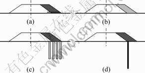
Fig.7 Treatment techniques analyzed: (a) Geosynthetic reinforcement; (b) Light-weight embankment; (c) Deep mixed column; (d) Separating wall
The light-weight embankment is backfilled with fly-ash material (Fig.7(b)). The cement deep mixed columns are embedded in the ground under the new embankment and the slope of existing embankment as well (Fig.7(c)). The length of the deep mixed column is 10 m with 1.5 m column spacing and 0.5 m column diameter. The embedded depth of the deep mixed column was selected to penetrate the soft layer in the ground and reach the underlying stiff layer. The deep mixed column was modeled as the stabilized soil with different parameters from nature soil. The Duncan-Chang parameters for the deep mixed column and the fly-ash used in the calculation are listed in Table 2 [20-21].
The separating wall was simulated as an elastic beam embedded into the ground, with an elastic modulus of 90 MPa and a Poisson ratio of 0.167 [19]. The separating wall has 15 m in length and 0.5 m in thickness. The thickness selection of the separating wall is based on the balance of reducing its self-weight and having enough bending strength. The conducted sensitivity analysis shows that the appropriate wall thickness is around 50-70 cm. The interaction between the beam and surrounding soil was simulated using the same contact element between the reinforcement and soil. The location of the separating wall is under the foot of the slope of the existing embankment for the purpose of restricting the horizontal movement in the soft ground due to widening (Fig.7(d)).
Table 2 Parameters for deep mixed column and fly-ash
5.2 Effect of treatment methods on deformation
The settlement distributions along the surface of the embankment using different treatment techniques after widening are compared in Fig.8. The treatments reduce the upper lift at the center of the existing embankment and the settlement of the new embankment as well, and thus reduce the differential settlements. Among the four treatment techniques, the light-weight fly-ash embankment causes the least settlement and the corresponding differential settlements. The transverse gradient decreases from 0.5%-1.3% to 0.26%-0.8% with the fly-ash backfill material. Comparatively, the rank of four treatment technologies is: 1) light-weight embankment, 2) deep mixed column, 3) separating wall, and 4) geosynthetic reinforcement.
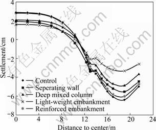
Fig.8 Distributions of settlement on top of embankment (b= 8.5 m)
The distributions of horizontal displacement along the surface of the embankment using different treatment techniques after widening are compared in Fig.9. It is shown that the treatments reduce the maximum horizontal displacement at the shoulder of the existing embankment. Similarly, the light-weight fly-ash embankment causes the least horizontal displacement among the four treatment techniques. The maximum horizontal displacement decreases from 2.76 to 1.44 cm by using the fly-ash backfill material. The relative rank of four treatment technologies is the same as the rank from the analysis of differential settlements.
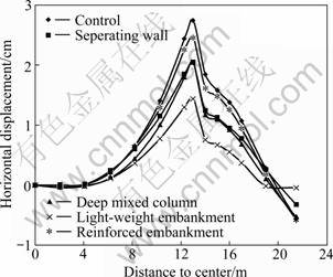
Fig.9 Distributions of horizontal displacement on top of embankment (b=8.5 m) (Positive means moving away from centerline, and vice versa)
5.3 Effect of treatment methods on stress distributions
The maximum shear stress contour using geosynthetic reinforcement after widening is plotted in Fig.10(a). Compared with Fig.5(b), the reinforcement reduces the concentration area of high shear stresses, especially for the soil at the vicinity of the reinforcement. The reduction of shear stresses could contribute to the increase of embankment stability. The effect of reinforcement is expected to be more significant with higher modulus of reinforcement and/or softer ground such that the ��tensile effect�� of reinforcement could be more excited.
As shown in Fig.10(b), for the case of using deep mixed column, the stress concentration is located around the columns because the deep mixed columns have greater shear strength than the surrounding soils. The maximum principal stresses around the deep mixed column are much greater than the surrounding soil at the same depth. This indicates that the high-strength deep mixed columns and the underlying soil under the soft layer bear the most embankment load and thus reduce the settlements and horizontal displacements of soft soils.
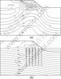
Fig.10 Shear stress contour using geosynthetic reinforcement (a) and maximum principal stress contour using deep mixed column (b) after widening (Unit: kPa)
6 Conclusions
1) It is found that the embankment widening induces transverse gradient change due to differential settlements and horizontal outward movements at the shoulder of the existing embankment. Embankment widening also increases the shear stress along the slope of the existing embankment, especially at the foot of slope. This could affect the serviceability of pavement and induce longitudinal pavement cracking at the joint.
2) The failure potential due to embankment widening may increase with the increase of widening width when the widening width is smaller than 8.5 m, but may decrease with the increase of widening width when the widening width is greater than 8.5 m.
3) Through the comparison of the reduction of differential settlements and horizontal displacements, the relative rank of four treatment technologies is: light- weight embankment, deep mixed column, separating wall, and geosynthetic reinforcement. The transverse gradient change decreases from 0.5%-1.3% to 0.26%-0.8% and the maximum horizontal displacement decreases from 2.76 cm to 1.44 cm by using the fly-ash backfill material.
References
[1] LUDLOW S J, CHEN W F, BOURDEAU P L, LOVELL P L. Embankment widening and grade raising on soft foundation soils. Phase 2, Research project final report: joint highway research project [R]. West Lafayette: Purdue University, 1993.
[2] VOS E, COUVREUR J F, VERMAUT M. Comparison of numerical analysis with field data of a road widening project on peaty soil [C]// Proceeding of International Workshop: Advances in Understanding and Modeling the Mechanical Behavior of Peat. Balkema, Rotterdam, 1994: 267-274.
[3] WANG Hao, HUANG Xiao-ming. Centrifuge model test and numerical analysis of embankment wideningon soft ground [C]// Proc Applications of Advanced Technologies in Trans Eng of the 8th International Conf. ASCE T&DI, Beijing, China, 2004: 548-553.
[4] HAN Jie, HUANG Jie, LIU Song-yu, HONG Zhen-shun. Stresses and deformations induced by widening of existing embankments over soft soils [C]// Proceedings of the International Symposium of Lowland Technology. Saga, Japan, 2006: 201-205.
[5] LING Jian-ming, QIAN Jin-song, HUANG Qin-long. Failure mechanism and design criterion for low-volume roads subgrade widening [R]. Transportation Research Record 1989, TRB, National Research Council, Washington, D.C., 2007: 135-141.
[6] DESCHAMPS R J, HYNES C S, BOURDEAU P. Embankment widening design guidelines and construction procedures [R]. West Lafayette: Purdue University, 1999.
[7] HAN J, AKINS K. Case Studies of geogrid-reinforced and pile-supported earth structures on weak foundation soils [C]// O��NEILL M W, TOWSEND F C. Proceedings of the International Deep Foundation Congress, Geotechnical Special Publication No. 116, Deep Foundations 2002. Orlando (USA), ASCE, 2002: 668- 679.
[8] van MEURS A, van den BERG A, VENMANS A A M, ZWABENBURG C. Embankment widening with the gap-method [C]// Proceedings of the 12th European Conference on Soil Mechanics and Geotechnical Engineering. Amsterdam, Netherlands, 1999: 1133-1138.
[9] ALLERSMA H G B, RAVENSWAAY L, VOS E. Investigation of road widening on soft soils using a small centrifuge [J]. Journal of Transportation Research Record, 1994(1462): 47-53.
[10] FORSMAN J, UOTINEN V. Synthetic reinforcement in the widening of a road embankment on soft foundation [C]// Geotechnical Engineering for Transportation Infrastructure. Balkema, Rotterdam, 1999: 1489-1496.
[11] HUANG Xiao-ming, WANG Hao. Comparison between responses of reinforced and unreinforced embankments due to road widening [J]. Journal of Central South University of Technology, 2009, 16(5): 857-864.
[12] HAN J, OZTOPRAK S, PARSONS R L, HUANG J. Numerical analysis of foundation columns to support widening of embankments [J]. Computers and Geotechnics, 2007, 34: 435-448.
[13] KRAHN J. Stress and deformation modeling with SIGMA/W [R]. GEO-SLOPE International, 2004.
[14] DUNCAN J M, CHANG C. Nonlinear analysis of stress and strain in soils [J]. Journal of the Soil Mechanics and Foundations Division, 1970, 96(5): 1629-1653.
[15] CHEN Xiao-bin, ZHANG Jia-sheng, AN Guan-feng. Test study of red stone granular soil��s rheological property in road embankment engineering [J]. Journal of Central South University of Technology: Science and Technology, 2007, 38(1): 154-159. (in Chinese)
[16] DEND Jian, BIAN Li. Response and energy dissipation of rock under stochastic stress waves [J]. Journal of Central South University of Technology, 2007, 14(1): 111-114.
[17] XU Zhe-zhong, SU Chao. The design of ground treatment on the joint of Hu-ning and Xi-cheng expressway [J]. Advances in Science and Technology of Water Resources, 1998, 18(2): 49-51. (in Chinese)
[18] LIU H L, CHARLES W W N G, FEI K. Performance of a geogrid-reinforced and pile-supported highway embankment over soft clay: Case study [J]. Journal of Geotechnical and Geo-environmental Engineering, 2007, 133(12): 1483-1493.
[19] GUO Zhi-bian. The design and settlement analysis of the joint embankment on soft soil [D]. Nanjing: Transportation College of HoHai University, 1999. (in Chinese)
[20] XU Yang, XIE Kang-he, LU Ting-hao. Consolidation analysis of composite ground with lime-fly ash columns by 3D FEM [J]. Chinese Journal of Geotechnical Engineering, 2002, 24(2): 254-256. (in Chinese)
[21] WANG Zhi-liang, YIN Zong-ze, LI Yong-chi. Practical method for FEM analysis of embankment settlement with Duncan-Chang model [J]. Rock Science and Mechanics, 2005, 26(7): 1085-1089. (in Chinese)
(Edited by YANG Bing)
Received date: 2010-03-05; Accepted date: 2011-01-10
Corresponding author: HUANG Xiao-ming, Professor, PhD; Tel: +86-25-83795184; E-mail: huangxm@seu.edu.cn
