

J. Cent. South Univ. (2020) 27: 144-154
DOI: https://doi.org/10.1007/s11771-020-4284-3

Performance of magnetorheological elastomer based torsional vibration isolation system for dynamic loading conditions
PRAVEEN Shenoy K1, 2, KUCHIBHATLA Sai Aditya Raman2,SINGH Abhishek Kumar1, 2, GANGADHARAN K V1, 2
1. Department of Mechanical Engineering, National Institute of Technology Karnataka, Surathkal, Mangalore-575025, India;
2. Centre for System Design, National Institute of Technology Karnataka, Surathkal, Mangalore-575025, India
 Central South University Press and Springer-Verlag GmbH Germany, part of Springer Nature 2020
Abstract:
Vibration isolation is an effective method to mitigate unwanted disturbances arising from dynamic loading conditions. With smart materials as suitable substitutes, the conventional passive isolators have attained attributes of semi-active as well as the active control system. In the present study, the non-homogenous field-dependent isolation capabilities of the magnetorheological elastomer are explored under torsional vibrations. Torsional natural frequency was measured using the serial arrangement of accelerometers. Novel methods are introduced to evaluate the torsional stiffness variations of the isolator for a semi-definite and a motor-coupled rotor system. For the semi-definite system, the isolation effect was studied using the frequency response functions from the modal analysis. The speed-dependent variations for motor-coupled rotor system were assessed using the shift in frequency amplitudes from torque transducers. Finite element method magnetics was used to study the variations in the non-homogenous magnetic field across the elastomer. The response functions for the semi-definite rotor system reveal a shift in the frequency in the effect of the magnetic field. Speed-dependent variations in the frequency domain indicate an increment of 9% in the resonant frequency of the system.
Key words:
Cite this article as:
PRAVEEN Shenoy K, KUCHIBHATLA Sai Aditya Raman, SINGH Abhishek Kumar, GANGADHARAN K V. Performance of magnetorheological elastomer based torsional vibration isolation system for dynamic loading conditions [J]. Journal of Central South University, 2020, 27(1): 144-154.
DOI:https://dx.doi.org/https://doi.org/10.1007/s11771-020-4284-31 Introduction
Rotating members are susceptible to torsional vibrations originating from various forces like asymmetric defects, gyroscopic effects, internal damping and forces inherent within the system. These vibrations are often seen as a cause for concern in power transmission systems and may lead to severe damage or failure under uncontrolled conditions. As observed by RAN et al [1], all rotatory elements experience torsional vibrations to variable degrees, either during start-up, shutdown or even during continuous operation. The severity of these vibrations is minimum under shorter dwell time in the resonance region. However, the results are harmful, if the system resonates for a sustained interval of time. To ensure reliability and safety of the rotating system, it is important to analyse its response characteristics under dynamic loading conditions.
Vibrations in dynamic systems are mitigated by employing either vibration absorbers [2] or vibration isolators [3]. In the absorption technique,as shown in Figure 1(a) a secondary spring-mass, damper system is attached to the primary system at its highest inertia point. On the contrary, vibration isolation is achieved (Figure 1(b)) by attaching viscoelastic rubber isolators in between the source of vibration and the primary system.
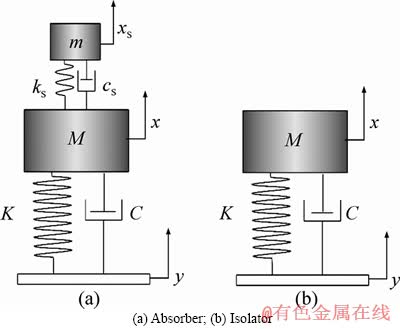
Figure 1 Schematic of vibration attenuation techniques:
Passive isolators work efficiently in mitigating vibrating amplitudes for fixed operating conditions. However, their isolation performance varies significantly, due to poor adaptability to fluctuations in the working frequencies.
This limitation is overcome by magnetorheological (MR) materials. These have the ability to significantly change their properties in the effect of the magnetic field, owing to which dynamic changes in frequencies are easily addressed. The MR materials are divided into magnetorheological fluid (MRF) [4], the fluid form and its solid analogue known as magnetorheological elastomer (MRE) [5]. The former consists of a non-magnetized liquid medium such as silicone, mineral oil, polyesters or polyether suspended with iron particles. MRE, on the other hand, has a solid medium of a non-magnetised viscoelastic matrix with iron particles interlocked in between. The viscous medium of the MRF allows it to be effectively used as shock absorbers in automotive vehicles [6]. However, sedimentation of iron particles and fluid leakage, by and large, restricts its use extensively. Contrary to this, MRE overcomes those issues and is found effective in applications of adaptive dynamic vibration absorbers, smart isolators in-seat vibration isolation and suspension bushings in automobile [7-9]. Further, various control strategies have been adapted for the vibration control using the adaptive nature of the MRE [10, 11].
MRE is classified based on the type of matrix (hard or soft), the type of filler particle, shape and size of the filler or the percentage volume of the filler. Past studies by EEM et al [8] and LI et al [9], suggest the optimal volume percentage of the carbonyl iron particles, (CIP) in between 25% and 35%. In addition to this, it is seen that a smaller particle size offers better performance in terms of loss factor. Furthermore, MRE is categorized based on the application of magnetic field during the curing process. Field-induced curing of MRE is termed anisotropic while the no-field process is termed as isotropic.
The characterization of MRE has been well researched for parameters such as magnetic field, input frequency, operating temperature and input strain rate [14-18]. It is seen that the complex stiffness of the viscoelastic material increases with the increase in magnetic field and operating frequency. However, with the increase in the operating temperature and strain rate, the stiffness decreases. The strain-dependent decrease in the stiffness is attributed to the Payne effect often exhibited in viscoelastic materials [19]. Apart from the stiffness, the influence of the above parameters on the dynamic damping has also been explored. Increase in the energy dissipation is observed with weak magnetic fields and at higher strain rates [20, 21]. Nevertheless, it is observed that damping reduces at stronger magnetic fields, while the influence of frequency is found to be relatively less.
As shown by POOJARY et al [22] MRE is observed to be an effective isolator and absorber in low temperature-low strain conditions for a frequency of 60 Hz beyond which the saturation of the moduli sets in.As stated earlier, MRE based absorbers and isolators have been effectively used for translatory vibration conditions. For torsional loading conditions, an absorber was studied under compressive loading conditions by HOANG et al [23, 24]. Complex elastic modulus was obtained for the elastomer under varying magnetic fields. Numerical simulations carried out revealed a significant reduction of approximately 60% in the system��s angular displacement. Though MRE has been considerably explored in translatory conditions, the potential of MRE for torsional vibration isolation has not been well explored. The present study addresses the isolation capabilities of an isotropic MRE for a semi-definite rotor system, and a motor coupled rotor system. Novel methods are introduced to comprehend the isolation competences under non-homogenous magnetic fields.
2 Preparation of MRE
Constituents of MRE comprise of room temperature vulcanized silicone rubber (Dow Corning, Xiameter-3483) as the matrix and carbonyl iron powder (CC grade of average diameter 5 ��m) as the particle ingredient. The process involves mixing the ingredients in the required proportion (27% by volume of the CIP) [25]. The mix is transferred to the mould (�� 60 mm, 10 mm thick) and is degassed in a desiccator using a vacuum pump to remove the entrapped air bubbles. Curing is carried out for 24 h at room temperature without magnetic field.
3 Methodology
3.1 Identification of torsional natural frequency
Any rotating system often consists of torsional, bending and lateral frequencies. To differentiate the torsional mode, a serial arrangement of accelerometers (SAA) [26] is adopted in the study. The method includes two identical accelerometers (equal sensitivity) arranged as shown in Figure 2(b). This enhances the torsional natural frequency and undesirable bending and lateral frequencies are restrained. Similarly, the parallel arrangement of accelerometers (Figure 2(a)) enhances the bending frequency. For the lateral frequency mode, a single axis accelerometer is used with an impact force applied, as shown in Figure 2(c).
The harmonic response for SAA is given as,
 (1)
(1)
where Sij is the harmonic response in SAA measurement, ��ri and ��rj are the angular displacement terms, ��r is the torsional natural frequency, Tj is the harmonic torque applied on the disks.
The harmonic signal in torsional mode is given as
 (2)
(2)
The FRF for the torsional frequencies is given as
 (3)
(3)
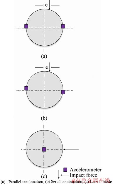
Figure 2 Accelerometer arrangements:
3.2 Vibration isolation for semi-definite rotor system
With the torsion mode ascertained using the SAA; the field-dependent complex modulus of the MRE for a semi-definite rotor system is evaluated. This is desirable as a semi-definite system exemplifies an actual rotating system under constant velocity. The system is excited using an impact hammer. The resulting frequency response function (FRF) is recorded in the absence and presence of magnetic field using a torque sensor. Corresponding loss factor and shift in resonance frequency are evaluated from the FRF graphs.
Figure 3 represents the semi-definite system for torsional 2DoF system. J1 and J2 signify the rotational inertial component. K* defines the field dependent complex stiffness modulus for viscoelastic materials. In general, the complex stiffness moduli consist of the stiffness part of the MRE (represented as K��) and the energy dissipation component (represented as K��). This is represented as
K*=K��+iK�� (4)
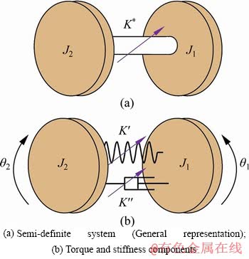
Figure 3 Schematic of semi-definite rotor system:
For a semi-definite system, the equations of motion are given as

For the sinusoidal input, the angular displacement is given as

Upon substituting,

From the determinants, the frequency components are:
 (5)
(5)
It is to be noted that for a semi-definite system, the zero root corresponds to the rigid mode frequency, which is a distinctive feature of free-free systems.
The loss factor of the system is evaluated by the half-power method (Figure 4) [3]. The loss factor is obtained from the quality factor, which is defined as the ratio of the resonance frequency to its frequency bandwidth. It is given as
 (6)
(6)
where f2 and f1 correspond to the frequency values at 0.707 Q, on either side of the resonance frequency, f.
The relation between quality factor and the loss factor is given as [3]
 (7)
(7)
It is seen that the above relation holds good for low viscous materials. For highly viscous materials, the loss factor [21, 22, 29] is modified as
 (8)
(8)
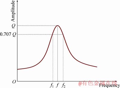
Figure 4 Half-power method
3.3 Speed-dependent analysis
With the semi-definite rotor system analysed, the torsional system is subjected to continuous rotations. Two identical DC motors are connected at input and output ends of the shaft respectively. The rotational inertia for the system is provided by the discs (Mild Steel) and the DC motors. To ensure that the inertial elements are lumped, the discs are connected close to the DC motors. The input DC motor is operated at varying speeds and the torque amplitude from the transducers is recorded. The signal is analyzed in the frequency domain by performing a fast Fourier transform (FFT). Torque values are converted to corresponding angular displacements.
The relation between torque, angular displacement and torsional stiffness is [30]:
 (9)
(9)
where �� is angular displacement (rad), T is input torque (N��m), Kt is torsional stiffness (N��m/rad).
The torsional stiffness is obtained from the frequency domain representation of the signal (corresponding to the maximum value of the FFT). For the torsional natural frequency (��n), Kt for the given rotational inertia, J is estimated from the relation
 (10)
(10)
To ensure that the torsional system is free from the frequencies of the supporting rigid base, the natural frequencies of the rigid base are obtained using roving hammer test [31]. To establish consistency in results, an average of 10 samples is obtained. Two identical MRE test samples are used to ensure consistency and accuracy. To address issues associated with the deformation history, the MRE is allowed a relaxation period of 20 min before successive measurements [32].
4 Experimental setup
The setup comprises of two aluminium rods, connected by an MRE coupler (Figure 5). Two discs (mild steel) are attached at the free ends of either shaft. The torsional natural frequency of the system is obtained using four triaxial accelerometers (measurement specialities Inc.), in a serial arrangement. The semi-definite rotor system includes the response functions obtained using a torque sensor (HBM, T22) and a PCB peizotronics impact hammer.For the speed-dependent tests (Figure 6), 2 DC motors (Dynaflux, 1 HP) are used. The input DC motor is run at variable speeds using a Sorenson DC power supply and the torque signals on the input and output ends are measured. The sensors and the bearings are firmly supported on the rigid base. 8 N52 permanent magnets (25 mm��25 mm��12 mm) provide the non-homogenous magnetic field, which is measured using a Gaussmeter (Lake Shore, Model 410). A distance of 20 mm is maintained between the magnets and either end of the MRE. A single axis accelerometer (YMC Piezotronics Inc.) is used to estimate the frequency response of the rigid base. The data are read using NI 9234, which is interfaced using LabVIEW. The consistency in results is maintained by repeating the tests 10 times.
Finite element method magnetics (FEMM), is used to envisage the 2D, non-homogenous magnetic field distributions through MRE. Figure 7 shows the contour plot for the field variation across the thickness and the diameter of a section of the elastomer. The plots reveal a decrease-increase trend in the field distribution across the MRE with the maximum at the circumference. Since the maximum shear occurs on the outer boundary of the elastomer, the non-homogenous field distribution is a viable option to counter space constraints as in the case of electromagnets. The average field measured using the gaussmeter across the diameter was 0.15 T.
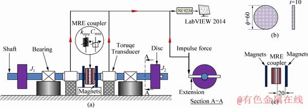
Figure 5 Schematic of torsional vibration isolation system for semi-definite rotor system (a), MRE sample dimensions (b) and distance between MRE sample and magnets (c) (Unit: mm)
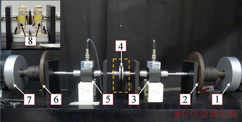
Figure 6 Experimental setup for torsional vibration isolation system without and with magnets (1-DC motor (Input end); 2, 6-MS disk; 3-Torque transducer (Input end); 4-MRE; 5-Torque transducer (Output end); 7-DC motor (Output end); 8-Neodymium magnets)
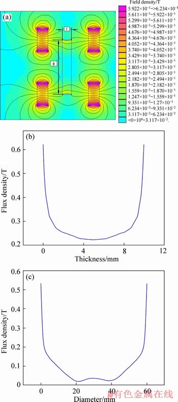
Figure 7 Contour plots (a) of field variation over thickness (b) and diameter (c) of MRE sample
5 Results and discussion
To ensure that the system is not influenced by the frequency components of the supporting base, a roving hammer test is carried out. The details about the experiment are as discussed in Ref. [31].
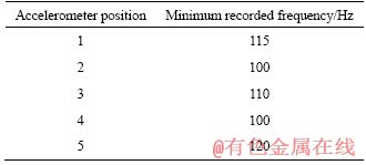
Table 1 shows the least obtained frequencies of the rigid base member. As seen, the base frequencies are comparatively higher than the expected torsional natural frequency of the system, which shows the system isolation from disturbances of the rigid base.
Table 1 Minimum recorded frequencies of rigid base
5.1 Determination of torsional, bending and lateral natural frequencies
It is observed that with the SAA, the second torsional natural frequency of the system is observed at 13.5 Hz. Further, the parallel arrangement of accelerometers (PAA) indicates the bending mode at 42 Hz [31]. The lateral mode (Figure 8) is obtained at 70 Hz. From the results, it is affirmed that the torsional mode is unaffected by the bending and lateral frequency components, confirming that the isolation experiments further carried out are for pure torsional vibrations.
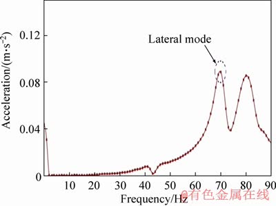
Figure 8 Lateral resonant frequency
5.2 Vibration isolation for semi-definite rotor system
The FRF of the semi-definite rotor system in the absence and presence of magnetic field is shown in Figure 9. In the absence of the field, the FRF peaks at 13.5 Hz, signifying the second torsional natural frequency of semi-definite rotor system. In the presence of a non-homogenous magnetic field, the peak shifts to a frequency of 14.5 Hz, resulting in the drop in amplitude. This asserts the isolation capability of the MRE isolator. The changing trends in the shear properties for torsional loading conditions vary on similar lines as that of the translatory shear conditions. The moduli improvement is elucidated with the Dipole mechanism with a unit cell of the CIP-silicone matrix [5, 25]. In the absence of magnetic field, the force of attraction between the individual CIPs is zero. This results in CIP offering less resistance to the input displacement, which results in lower complex moduli of the viscoelastic MRE. In the presence of the field, however, the iron particles are energised forming a chainlike structure, offering a compressive force on the underlying silicone matrix. This increases the resistance to the torsional shear input experienced by the MRE, leading to the increase in the complex moduli. With the bulk of the MRE considered, the total stiffness increases thereby, resulting in a shift in the system��s torsional natural frequency.
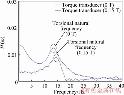
Figure 9 FRF for semi-definite rotor system under 0 T and 0.15 T
5.3 Loss factor
Loss factor represents the ability of materials to absorb the vibration energy. For a viscoelastic material, it is calculated as per Eqs. (7) and (8). The loss factor obtained from the torsional vibration test is shown in Figure 10. The results reveal a negligible difference between the actual and the approximate values which indicate that both the approaches can be successfully used to estimate the loss factor of MRE since its value is less than 0.3 [28]. The numerical values of the loss factor obtained are in the range of 0.3 which is significantly higher compared to that of an unfilled rubber. The MRE, which is a filled rubber by virtue of its microstructure, has a significant contribution due to the presence of interfaces. Under dynamic loads, these interfaces are disturbed thereby increasing the damping. The loss factor registered during torsional tests has a close match with the results reported in the lateral shear experiments [22]. This suggests that the damping in MRE is independent of the direction of the shear loading. However, the displacement of the particles in torsion may differ at the centre of the elastomer when compared to the particles at the circumference.
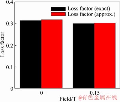
Figure 10 Loss factor vs field
It is seen that the magnetic field dependent variation in the loss factor is not significant as reported in the past studies [9]. This phenomenon is attributed to the fact that as the filler percentages increase, the amount of rubber present in the matrix reduces. This reduces the damping effect due to the filler-matrix interface. Past studies [33] also reveal that for higher volume fractions of the filler materials, the increase in the interface damping is more remarkable only at higher magnetic fields. This showcases the reduced influence of the magnetic field on the loss factor.
Further, the energy dissipation capabilities of the MRE depend on many factors such as the intrinsic damping capacity of the matrix, the interaction between the matrix and the carbonyl iron particles (CIP), the interaction between the individual CIP under the influence of the magnetic field. Of these, the interaction between the CIP and the matrix is influenced by the total number of carbonyl iron particles per unit volume of the MRE sample. During the shearing of the MRE, the individual iron particle is subjected to constant cyclic deformation. Due to the force of friction between the particle and the rubber strands, the damping at the interface increases. With the increase in the volume fraction of the filler elements, the total number of the CIP per unit volume of the MRE increases, which increases the overall damping among the CIP and the matrix.
5.4 Speed-dependent torsional vibration isolation
With the isolation capability for the semi-definite rotor system analysed, the MRE isolator is studied for continuous rotation conditions using DC motors. Figure 11 shows the frequency response from the input and output torque transducers of the system. The motor is operated at different speeds and the frequency response for each of the speeds is consolidated and plotted. The variations in the frequency response signify the existence of torsional natural frequency. In general, torsional vibrations are a typical phenomenon arising from unbalance present in rotational systems. The effects of torsional natural frequency are not significant below or beyond the resonance region. However, a significant influence of the torsional vibrations is seen as it approaches the resonance region due to the amplification of the unbalance forces of the system.
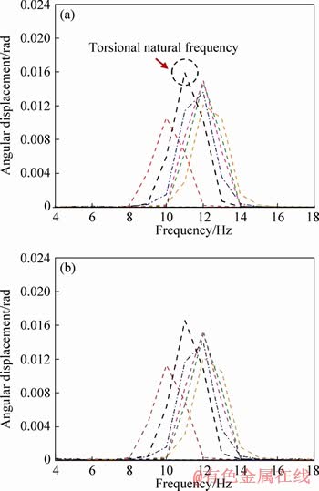
Figure 11 Frequency domain plots for angular displacement versus frequency at 0 T for input transducer (a) and output transducer (b)
It is evident that the maximum amplitude of the system is observed at 11.15 Hz which signifies the torsional natural frequency of the system which is in contrast with the maximum amplitude observed at 13.5 Hz in the semi-definite rotor system. This variation in the frequency is attributed to the additional rotational inertia provided by the DC motors at either end of the shafts. From Eq. (5), it is seen that, with the increase in the rotational inertia, the natural frequency of the system reduces.
With the introduction of non-homogenous magnetic field (Figure 12), the plots reveal a shift in frequency to 12 Hz. With the frequency shift of 9%, the field dependent behaviour on the properties of the MRE is showcased. This is attributed to the increase in the torsional stiffness offered by the MRE under the influence of the magnetic field.
It is also evident that under the influence of the magnetic field, there is a reduction in amplitude of the transducer at 11.15 Hz. Due to the shift in the natural frequency of the system, the amplitude of angular displacement for the 11.15 Hz frequency reduces from 0.016 rad at 0 T to 0.01 rad under the influence of 0.15 T. This highlights the usefulness of the MRE in reducing/isolating the system at the operating frequency of 11.15 Hz. The same has been highlighted in Figure 13.
6 Conclusions
In this study, the torsional vibration isolation capabilities of MRE under non-homogenous field conditions are studied. Novel methods are introduced to comprehend the isolation capabilities for a semi-definite rotor system and continuous rotating systems. The torsional natural frequency for the developed semi-definite rotor system is identified at 13.5 Hz using serial accelerometer arrangement. The shift in the torsional natural frequency under the non-homogenous magnetic field reveals the capability of the developed setup in portraying vibration isolation for torsional loading conditions. The well-established dipole mechanism explains the stiffening of the elastomer which leads to a shift in natural frequency. The loss factor of MRE under the torsional loading condition is 0.3 and can be effectively obtained using both the exact solution and the approximate method. The larger volume fraction of the filler reduced the field induced variation in the loss factor. Under continuous rotations, the shift in the torsional natural frequency is 9% under the influence of magnetic field. Moreover, the contribution of additional rotational inertial elements from the coupled DC motors reduces the torsional natural frequency of the system in comparison with the semi-definite system.
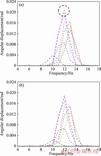
Figure 12 Frequency domain plots for angular displacement versus frequency at 0.15 T for input transducer (a) and output transducer (b)
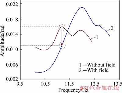
Figure 13 System isolation
Acknowledgements
The authors acknowledge the support from SOLVE: The Virtual Lab @ NITK (Grant number: No.F.16-35/2009-DL, Ministry of Human Resources Development) and experimental facility provided by Centre for System Design (CSD): A Centre of Excellence (http://csd.nitk.ac.in/) at National Institute of Technology Karnataka, India. The authors would also wish to thank Mr Umanath Poojary, Senior Research Fellow, CSD, for his invaluable inputs.
References
[1] RAN L, YACAMINI R, SMITH K S. Torsional vibrations in electrical induction motor drives during start-up [J]. Journal of Vibration and Acoustics, 1996, 118(2): 242-251. DOI: 10.1115/1.2889655.
[2] GAO P, XIANG C, LIU H, ZHOU H. Reducing variable frequency vibrations in a powertrain system with an adaptive tuned vibration absorber group [J]. Journal of Sound and Vibrations, 2018, 425: 82-101. DOI: 10.1016/j.jsv.2018. 03.034.
[3] RAO S S. Mechanical vibrations [M]. Pearson, 2010.
[4] RABINOW J. The magnetic fluid clutch [J]. Transactions of the American Institute of Electrical Engineers, 1948, 67: 1308-1315. DOI: 10.1109/T-AIEE.1948.5059821.
[5] JOLLY M R, CARLSON J D, MUNOZ B C. A model of the behaviour of magnetorheological materials [J]. Smart Materials and Structures, 1996, 5(5): 607-614. DOI: 10.1088/0964-1726/5/5/009.
[6] VICENTE J, KLINGENBERG D J, HIDALGO-ALVAREZ R. Magnetorheological fluids: A review [J]. Soft Matter, 2011, 7(8): 3701-3710. DOI: 10.1039/c0sm01221a.
[7] SUN S, DENG H, YANG J, LI W, DU H, ALICI G. Performance evaluation and comparison of magnetorheological elastomer absorbers working in shear and squeeze modes [J]. Journal of Intelligent Material Systems and Structures, 2015: 1757-1763. DOI: 10.1177/1045389X14568819.
[8] EEM S H, JUNG H J, KOO J H. Application of MR elastomers for improving seismic protection of base-isolated structures [C]// IEEE Transactions on Magnetics, 2011: 2901-2904. DOI: 10.1109/TMAG.2011.2156771.
[9] LI Y, LI J, LI W, DU H. A state-of-the-art review on magnetorheological elastomer devices [J]. Smart Material Structure, 2014, 23(12): 123001-123024. DOI: 10.1088/ 0964-1726/23/12/123001.
[10] LI W, ZHANG X, DU H. Development and simulation evaluation of a magnetorheological elastomer isolator for seat vibration control [J]. Journal of Intelligent Material Systems and Structures, 2012, 23(9): 1041-1048. DOI: 10.1177/ 1045389X11435431.
[11] QIAN L J, XIN F L, BAI X X, WERELEY N M. State observation�Cbased control algorithm for dynamic vibration absorbing systems featuring magnetorheological elastomers: Principle and analysis [J]. Journal of Intelligent Material Systems and Structures, 2017, 28(18): 2539-2556. DOI: 10.1177/ 1045389X17692047.
[12] LOKANDER M, STENBERG B. Improving the magnetorheological effect in isotropic magnetorheological rubber materials [J]. Polymer Testing, 2003, 22(6): 677-680. DOI: 10.1016/S0142-9418(02)00175-7.
[13] LOKANDER M, STENBERG B. Performance of isotropic magnetorheological rubber materials [J]. Polymer Testing, 2003, 22: 245-251. DOI: 10.1016/S0142-9418(02)00043-0.
[14] JOLLY M R, CARLSON J D, MUNOZ B C. The magnetoviscoelastic response of elastomer composites consisting of ferrous particles embedded in a polymer matrix [J]. Journal of Intelligent Material Systems and Structures, 1996, 7(6): 613. DOI: 10.1177/1045389X9600700601.
[15] ZHOU G Y. Shear properties of a magnetorheological elastomer [J]. Smart Material Structure, 2003, 12: 139-146. DOI: 10.1088/0964-1726/12/1/316.
[16] YANG J, GONG X, DENG H, QIN L, XUAN S. Investigation on the mechanism of damping behavior of magnetorheological elastomers [J]. Smart Material Structure, 2012, 21(12): 125015-125026. DOI: 10.1088/0964- 1726/21/12/125015.
[17] GONG X L, ZHANG X Z, ZHANG P Q. Fabrication and characterization of isotropic magnetorheological elastomers [J]. Polymer Testing, 2005, 24(5): 669-676. DOI: 10.1016/j.polymertesting.2005.03.015.
[18] XIN F, BAI X, QIAN L. Modeling and experimental verification of frequency-, amplitude-, and magneto- dependent viscoelasticity of magnetorheological elastomers [J]. Smart Material Structure, 2016, 25(10): 105002-105018. DOI: 10.1088/0964-1726/25/10/105002.
[19] PAYNE A R. The dynamic properties of carbon black loaded natural rubber vulcanizates. Part II [J]. Journal of Applied Polymer Science, 1962, 6(21): 368-372. DOI: 10.1002/app.1962.070062115.
[20] LI J F, GONG X L. Dynamic damping property of magnetorheological elastomer [J]. Journal of Central South University of Technology, 2008, 15(1): 261-265. DOI: 10.1007/s11771-008-0359-2.
[21] CHEN L, GONG X L. Damping of magnetorheological elastomers [J]. Journal of Central South University of Technology, 2008, 15(1): 271-274. DOI: 10.1007/s11771- 008-0361-8.
[22] POOJARY U R, HEGDE S, GANGADHARAN K V. Dynamic blocked transfer stiffness method of characterizing the magnetic field and frequency dependent dynamic viscoelastic properties of MRE [J]. Korea Aust Rheol J, 2016, 28(4): 301-313. DOI: 10.1007/s13367-016-0031-6.
[23] HOANG N, ZHANG N, LI W H, DU H. Development of a torsional dynamic absorber using a magnetorheological elastomer for vibration reduction of a powertrain test rig [J] Journal of Intelligent material systems and structures, 2013, 24(16): 2036-2044. DOI: 10.1177/1045389X13489361.
[24] HOANG N, ZHANG N, DU H. A dynamic absorber with a soft magnetorheological elastomer for powertrain vibration suppression [J]. Smart Material Structure, 2009, 18(7): 074009. DOI: 10.1088/0964-1726/18/7/074009.
[25] POOJARY U R, HEGDE S, GANGADHARAN K V. Dynamic deformation�Cdependent magnetic field�Cinduced force transmissibility characteristics of magnetorheological elastomer [J]. Journal of Intelligent Material Systems and Structures, 2017, 28(11): 1491-1500. DOI: 10.1177/ 1045389X16672730.
[26] KUANG J H, LIN J F. Accelerometer pair measurements for shaft dynamic parameters analysis [C]// Proceedings of SPIE. The International Society for Optical Engineering, 1994: 1649-1655.
[27] HOORZAD H. Characterization of viscoelastic materials using atomic force microscopy [D]. Alberta: University of Calgary, 2017: 61.
[28] GRAESSER E, WONG C. The relationship of traditional damping measures for materials with high damping capacity: A review [M]. STP1169-EB M D: Mechanics and Mechanisms Damping. ASTM, 1991: 316-328. DOI: 10.1520/STP17969S.
[29] CARFAGNI M, LENZI E, PIERINI M. The loss factor as a measure of mechanical damping [C]// SPIE Proceedings Series, 1998: 580-584.
[30] WILSON W K. Practical solution of torsional vibration problems: With examples from marine, electrical, aeronautical, and automobile engineering practice, vol. 1 [M]. Chapman & Hall, 1956.
[31] SHENOY K P, SINGH A K, RAMAN K S A, GANGADHARAN K V. Experimental investigation of torsional vibration isolation using magneto rheological elastomer [C]// MATEC Web of Conferences, 2018: 144. DOI: 10.1051/matecconf/201714401007.
[32] STACER R G, HUBNER C, HUSBAND D M. Binder/filler interaction and the nonlinear behavior of highly-filled elastomer [J]. Rubber Chemical Technology, 1990, 63(4): 488-502. DOI: 10.5254/1.3538268.
[33] HEGDE S, KIRAN K, GANGADHARAN K V. A novel approach to investigate effect of magnetic field on dynamic properties of natural rubber based isotropic thick magnetorheological elastomers in shear mode [J]. Journal of Central South University, 2015, 22(7): 2612-2619. DOI: 10.1007/s11771-015-2791-4.
(Edited by HE Yun-bin)
���ĵ���
���ڴ����䵯�����Ťת����ϵͳ�ڶ�̬���������µ�����
ժҪ��������һ�ּ����ڶ�̬������������Ҫ���ŵ���Ч�����������ܲ�����Ϊ���ʵ����Ʒ����ͳ����Դ�����������������ƺͰ��������Ƶ��ص㡣�ڱ��о��У�̽���˴����䵯������Ťת���µķǾ��ȳ���ظ������������ü��ٶȼƵĴ�����ʽ����Ťת����Ƶ�ʣ�������һ���µķ����������붨ת��ϵͳ�͵�����ת��ϵͳ�ĸ�������Ťת�նȱ仯������ģ̬�����е�Ƶ�캯�����о��˰붨ϵͳ�ĸ���Ч��������ת�ش�������Ƶ�ʷ�ֵ��λ��������������ת��ϵͳ���ٶ���ر仯��������Ԫ�����о��˷Ǿ��ȴų��ڵ��������ı仯���붨ת��ϵͳ����Ӧ������ʾ�˴ų�������Ƶ�ʵı仯��Ƶ������ٶ���ر仯����ϵͳ�Ĺ���Ƶ��������9%��
�ؼ��ʣ�Ťת���룻�붨ϵͳ�������䵯���壻�ٶ���ظ���
Received date: 2018-10-07; Accepted date: 2019-10-22
Corresponding author: PRAVEEN Shenoy K, PhD, Research Scholar; Tel:+91-08242473915; E-mail: praveen.me14f12@nitk.edu.in; ORCID: 0000-0002-6014-3391
Abstract: Vibration isolation is an effective method to mitigate unwanted disturbances arising from dynamic loading conditions. With smart materials as suitable substitutes, the conventional passive isolators have attained attributes of semi-active as well as the active control system. In the present study, the non-homogenous field-dependent isolation capabilities of the magnetorheological elastomer are explored under torsional vibrations. Torsional natural frequency was measured using the serial arrangement of accelerometers. Novel methods are introduced to evaluate the torsional stiffness variations of the isolator for a semi-definite and a motor-coupled rotor system. For the semi-definite system, the isolation effect was studied using the frequency response functions from the modal analysis. The speed-dependent variations for motor-coupled rotor system were assessed using the shift in frequency amplitudes from torque transducers. Finite element method magnetics was used to study the variations in the non-homogenous magnetic field across the elastomer. The response functions for the semi-definite rotor system reveal a shift in the frequency in the effect of the magnetic field. Speed-dependent variations in the frequency domain indicate an increment of 9% in the resonant frequency of the system.
