
Trans. Nonferrous Met. Soc. China 31(2021) 156-166
Effect of heat treatment conditions on ballistic behaviour of various zones of friction stir welded magnesium alloy joints
S. DHARANI KUMAR1, S. SURESH KUMAR2
1. Department of Mechanical Engineering, Sri Eshwar College of Engineering, Coimbatore, 641202, Tamil Nadu, India;
2. Department of Mechanical Engineering, Sri Sivasubramaniya Nadar College of Engineering, Chennai, 603110, Tamil Nadu, India
Received 19 March 2020; accepted 28 September 2020
Abstract:
Ballistic behaviour of different zones of post-weld heat-treated (PWHT) magnesium alloy (AZ31B) target against 7.62 mm �� 39 mm armour-piercing (AP) projectile with a striking velocity of (430��20) m/s was determined. Magnesium alloy (AZ31B) welded joints were prepared by using friction stir welding (FSW) process and subjected to different heat treatment conditions. The microhardness values of non-heat-treated and heat-treated FSW joints were investigated. The results indicated that PWHT process (250 ��C, 1 h) has improved the microhardness of heat-treated FSW joints. Scanning electron microscope (SEM) microstructure showed that heat treatment has caused the formation of fine ��-Mg grains and tiny precipitates and made the dissolution of ��-Mg17Al12 phase into the Mg matrix. The ballistic behaviour of PWHT zones was estimated by measuring the depth of penetration (DOP) of the projectile. Lower DOP value was observed for the base metal zone (BMZ) of a heat-treated welded joint. Post ballistic SEM examinations on the cross-section of all three zones of crater region showed the formation of adiabatic shear band (ASB).
Key words:
AZ31B magnesium alloy; post-weld heat treatment; ballistic behaviour; penetration depth; adiabatic shear band;
1 Introduction
In recent years many researchers have tried to use magnesium alloys for defence applications due to their better damping capability and lower density when compared to the steels and aluminium alloys. Mg alloys have been used in the defence tankers and defence aircrafts to decrease the mass and increase the fuel efficiency of the vehicle used in defence applications [1]. ABDULLAH et al [2] studied the ballistic resistance of cast AZ31B Mg alloy plates produced by disintegrated melt deposition (DMD) technique and reported that the addition of lead as reinforcement enhances the ballistic resistance. In the fabrication of defence tankers and vehicles structures, inevitably, there is a need of permanent and temporary joints. However, knowledge and selection of joint are most essential in the design of defence vehicle��s structures against the ballistic impact loads. The most common permanent joining technique is welding. Still, welding of magnesium is quite tricky, owing to its less surface tension and vapour pressure. However, traditional fusion welding techniques are not suitable for cast AZ31B Mg alloys due to the formation of solidification cracking, embrittlement and porosity in the weld zone [3,4]. The heat input during fusion welding process is higher compared to that during FSW [5]. THOMPSON et al [6] observed that the ballisitc limit of FSW 2xxx and 5xxx series of aluminium alloy joints is superior to that of gas metal arc welding (GMAW) aluminium alloy joints against the impact of armour-piercing (AP) projectile.
Generally, FSW is the most promising solid-state welding technique in which no melting occurs in the base metal (BM) and width of the heat affected zone (HAZ) is less. In the FSW process, a non-consumable tool will produce frictional heat combined with plastic deformation in the nugget zone (NZ) of FSW joint. FSW is being increasingly used in tanks and military vehicle applications [7]. SULLIVAN and ROBSON [8] determined the ballistic behaviour of thick AA7010-T7651 plates joined by FSW process and noticed that the loss of hardness in the HAZ region results in 20% reduction in ballistic limit. In addition, they found a linear correlation between hardness and ballistic performance. ERDEM et al [9] determined the hardness, microstructure and ballistic performances of friction stir welded 7039 aluminium alloy plates of different zones of NZ, HAZ and BMZ. The ballistic limits of the NZ and HAZ are observed to be lower than that of BMZ. HOLMEN et al [10] studied the metal inert gas (MIG) welded AA6082-T6 alloy plates against 7.62 mm AP projectile to determine the ballistic behaviour of different weld zones. It was observed that ballistic limit of the base metal was higher than that of other weld zones and the least ballistic limit occurs in the HAZ. JHA et al [11] determined the ballistic limit of aluminium 2219 alloy plates with 6.4 and 7.8 mm in thickness joined by tungsten inert gas (TIG) welding. They observed the formation of adiabatic shear band (ASB) which caused the separation of surfaces and resulted in solidified debris on the fracture surfaces.
It is important to study the ballistic failure mechanisms and damage fracture surface of targets after the ballistic impact test. A few ballistic fracture studies have been done on various ferrous [12] and non-ferrous alloys [13]. The improved strength and microhardness of the target caused reduction of ASB formation and reduced the depth of penetration (DOP) [14]. ASBs led to cracks and micro-pores in the crater region of a high strength thick steel plate in the tempered condition [15]. SUKUMAR et al [16] observed that 920 ��C WQ (Ti6Al4V) condition had a greater resistance to ASB formation when compared to 830 ��C slowly cooled and then aged (STA) (Ti6Al4V) condition, but it did not reveal better ballistic performance due to its lower strength when compared to 830 ��C STA condition. MANES et al [17] showed the formation of ASB along with ductile dimples through the coalescence and nucleation on the ballistic fracture surface of Al6061-T6 aluminium plates. The softening effect modifies the microstructure, accelerates the formation of dissolution and growth of coarse precipitates and results in the loss of mechanical properties. In order to restore the loss of these properties in different weld zones, one preference is to fully heat treat the welded components [8,18]. The increase in microhardness value in NZ of AA7075-T651 FSW joints after post-weld heat- treated (PWHT) process [19] was obtained. The PWHT AZ31B FSW Mg alloys considerably enhanced the tensile strength and microhardness at an annealing temperature of 250 ��C [20].
Reported literatures [20,21] showed that, PWHT process can significantly improve the hardness and modify the microstructure of the FSW joints. Published research works focused on the effect of FSW parameters on ballistic behaviour of aluminium alloy [8] and compared the ballistic limit between BM and welded aluminium alloy plates [9]. However, limited works were noticed on ballistic studies of PWHT FSW joints of magnesium alloy. It was observed that that there is an improvement in ballistic behavior with hardness; in a WZ it is likely to attain the same hardness with moderate microstructures, several of which might be highly harmful to loss of ductility and toughness [5]. EREEM et al [9] and SULLIVAN et al [21] have determined the ballistic properties of different friction stir welded zones such as NZ+TMAZ (thermo-mechanical affected zone), HAZ and BMZ of aluminium alloy. Limited attempts have been noticed to determine the performance and failure behaviour of NZ+TMAZ, HAZ and BMZ of the PWHT AZ31B magnesium alloy.
In the present work, an attempt has been made to determine the ballistic behaviour of PWHT AZ31B Mg joints (8 mm in thickness) using 7.62 mm AP projectiles. The PWHT test was carried out under different annealing conditions, such as (150 ��C, 1 h), (250 ��C, 1 h) and (350 ��C, 1 h), respectively.
2 Experimental
Magnesium plates with the dimensions of 50 mm ��50 mm �� 8 mm were used and Table 1 shows the chemical composition of DMD cast AZ31B Mg alloy.
In order to prepare square butt joints, taper pin tool made of H13 tool steel was used. Taper pin profile has shoulder diameter of 26 mm, pin diameter of 9 mm and length of 7.6 mm. The dimensions of the taper pin FSW tool are shown in Fig. 1.
Table 1 Chemical composition of DMD cast AZ31B Mg alloy (wt.%)
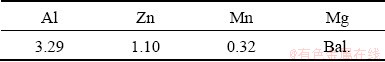
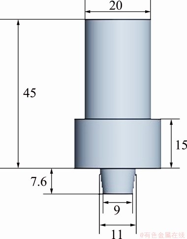
Fig. 1 Dimensions of taper pin FSW tool (Unit: mm)
The macro-level defect-free joint was prepared through a sequence of trial runs by changing the welding parameters such as tool rotation speed and welding feed which are listed in Table 2.
The trial runs indicated that rotation speed (1200 r/min) and welding feed (50 mm/min) are the optimum process parameters to produce defect-free FSW joints. Figure 2 shows the FSW joint obtained by using the above-mentioned parameters. The PWHT process was carried out in the electric furnace at three different annealing temperatures of 150, 250 and 350 ��C for a period of 1 h soaking time under vacuum condition.
The microhardness values of heat-treated and non- heat-treated welded joints were measured by using Vickers hardness tester with a load of 100 g and a dwell time of 15 s. For each specimen, three measurements were taken and an average value was reported. FSW and PWHT samples were subjected to metallographic examination to obtain the microstructural changes.
Ballistic experiments were carried out in three different weld zones such as NZ + thermo mechanically affected zone (TMAZ), HAZ and BMZ. Aluminium alloy 6062 having dimensions of 200 mm �� 200 mm �� 22 mm was used as the backing plate. The Al-6062 backing plate and PWHT Mg alloy as a front plate were firmly clamped together using C-clamps at four edges without any air gap. The mass of the cartridge and the projectile was 18.75 and 7.85 g, respectively. The ballistic experiments were conducted as per MIL-DTL��32333 standard. The PWHT target plates were impacted against 7.62 mm �� 39 mm AP projectile at 0�� angle of attack with a firing range of 10 m and striking velocity of the projectile was (430��20) m/s. The mass of the gun powder was varied from 1.20 to 1.25 g to obtain the required striking velocity. The schematic diagrams of ballistic setup and the AP projectiles used in the present study are shown in Fig. 3.
In each test, infrared light-emitting diode was used to measure the impact velocity of projectile. A total of three projectiles were fired to PWHT target plates to obtain the ballistic performance statistically. The DOP values were considered to determine the ballistic performance of different zones of the PWHT target plates. The DOP of the penetration channel was measured using a video measuring instrument with an accuracy of ��5 ��m. After the measurement of DOP value, the crater region of target plates was cut along the midpoint to investigate the nature of damage caused by the projectile impact. The damage behavior of crater sections was studied by using SEM.
Table 2 Macro graphs of different FSW joints prepared under different welding parameters
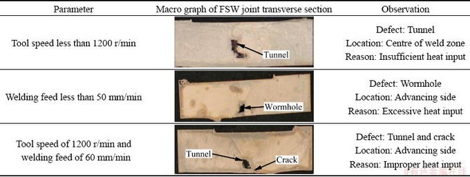
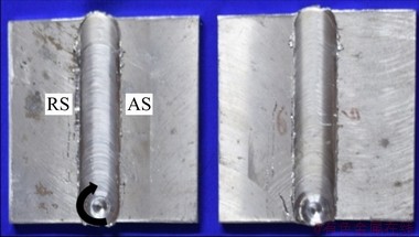
Fig. 2 Defect-free AZ31B friction stir welds
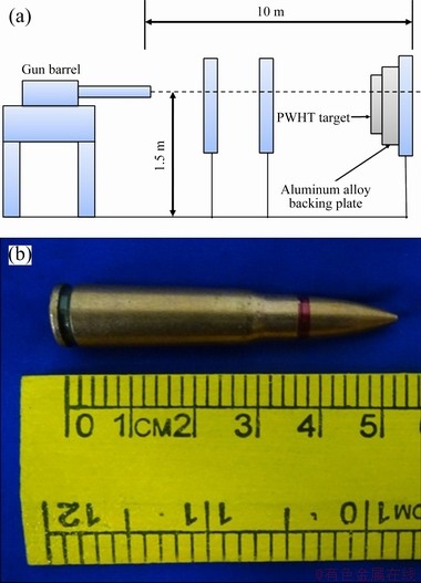
Fig. 3 Schematic diagrams of ballistic setup (a) and 7.62 mm �� 39 mm AP projectile (b)
3 Results and discussion
3.1 Microstructure
Figure 4 shows the SEM images of the AZ31B base metal (BM), non-heat-treated and heat-treated FSW joints. SEM image of BM shows the coarse and non-homogeneous distribution of ��-phase (Fig. 4(a)). The NZ-FSW (Fig. 4(b)) shows considerable changes in microstructure when compared to the BM. NZ-FSW consists of equiaxed grains with a few precipitate particles along the grain boundaries.
It is understood that the stirring action of the FSW tool locally produces plastic deformation and frictional heat; this causes the partial dissolution of ��-Mg17Al12 phase in the matrix. TUZ et al [22] reported that dissolution of the secondary phase was mainly due to the plastic deformation caused by the FSW tool. Hence, this produced the softening behaviour in the NZ compared to the BM. FSW reduced the size of the ��-phase particles in the NZ of Mg alloy [23,24]. Figure 4(c) shows the NZ-PWHT microstructure under annealing condition of 250 ��C and 1 h. The microstructure contains fine ��-Mg phase and significant dissolution of secondary ��-phase. However, the tiny precipitates were observed at the grain boundaries, due to the atomic diffusive flow of Mg and Al atoms. Hence, these strengthening precipitate particles make strong grain boundary and increase the strength of the joint. The HAZ-PWHT microstructure (Fig. 4(d)) exhibits coarse ��-Mg and discontinuous precipitations compared to the NZ-PWHT microstructure. However, HAZ only experiences thermal cycle but not any plastic strain during welding, even though its heat-treated region of microstructure shows imperfect recrystallization and a few retained ��-phases (��-Mg17Al12). SEM microstructure of BMZ-PWHT is shown in Fig. 4(e). It is evident that the presence of coarse ��-Mg is similar to HAZ and refined spherical Mg17Al12 phases. Mg17Al12 phases were refined because of the solid solution strengthening, which is the effect of annealing process. The grain sizes of NZ, HAZ and BMZ in the PWHT samples are about 10.2, 52.7 and 26.6 ��m, respectively.
3.2 Effect of PWHT temperature on micro- hardness
Figure 5 compares the average transverse microhardness of the three different heat-treated joints with that of non-heat treated one.
The microhardness of the HAZ of FSW joint was HV 54, while the microhardness values of the NZ and base metal were about HV 63 and HV 66, respectively. Compared to the base metal, lower microhardness was observed in the NZ, which is attributed to the dissolution of ��-phase. SINGH et al [25] also observed lower microhardness compared to the base metal. The least microhardness value was recorded in the friction stir welded zones, predominantly in the HAZ and TMAZ. However, these zones have undergone thermal softening effect caused by FSW tool. It was also observed that the variation of microhardness of the heat-treated welded joints was significantly influenced by the condition of heat treatment. The average microhardness values of NZ heat-treated welded joints obtained at annealing temperatures of 150, 250 and 350 ��C for 1 h were about HV 61, HV 68 and HV 56, respectively.
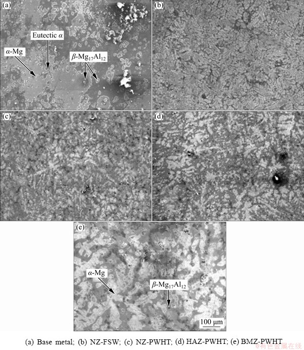
Fig. 4 SEM images of different zones of AZ31B magnesium alloys
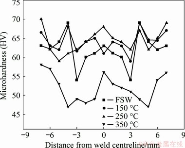
Fig. 5 Microhardness profiles of FSW and PWHT samples at different annealing temperatures
3.3 Ballistic failure mechanisms of different PWHT zones
Ballistic performance of the PWHT (250 ��C for 1 h) plate was determined by using 7.62 mm hard steel core projectile in the NZ+TMAZ, HAZ and BMZ. In each zone, three samples were tested and the corresponding DOP was measured using a video measuring instrument. The damage images of the front face and cross-sections of the NZ-PWHT, HAZ and BM target plates, impacted at a striking velocity of (430��20) m/s are shown in Figs. 6-8, respectively.
Figures 6(a) and (b) show the front face and cross-section images of the NZ+TMAZ crater region of PWHT targets, respectively.
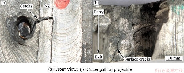
Fig. 6 Damage images of front face and cross-section of NZ-PWHT target plate after ballistic test
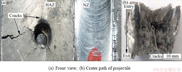
Fig. 7 Damage images of front side and cross-section of HAZ-PWHT target plate after ballistic test
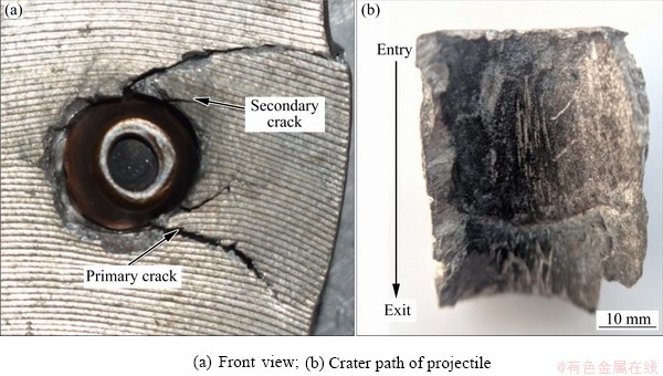
Fig. 8 Damage images of front face and cross-section of BM-PWHT target plate after ballistic test
The projectile impact caused the localized strain around the crater area, which led to the formation of surface crack in the weld region. It was found that the crater width at the entry was higher than that at the exit. Spalling mode failure was noted at the entry of the NZ where the hole diameter was bigger than the actual projectile diameter. It was due to the variation of hardness along the transverse direction. In addition, the ballistic failure mechanism changed from spalling to plugging mode in the middle. This type of failure was dominated by an induced shear stress during penetration of the projectile. The presence of small surface cracks at the exit of crater clearly indicates that there is loss of ductility.
Figures 7(a) and (b) show the damage images of front face and cross-sections of HAZ target plate. Radial cracks were observed on the front face of the HAZ. The contact of the projectile on the target reduced the strength and developed high compressive stress. The compressive stress waves changed the fracture behaviour from ductile to brittle mode. Hence, it led to the formation of more cracks around the crater region compared to the NZ. Theses cracks did not propagate towards the weld regions because these regions have higher microhardness and finer grains compared to the HAZ.
The plugging failure mode was observed on the crater cross-section of the HAZ. In addition to plugging failure, the ductile deformation was observed by extending the corners of crater at the entry.
Figure 8(a) shows front face image of BM target plate, revealing the presence of primary and secondary cracks. Large continuous cracks are known as primary cracks. The cracks are formed due to the initial stress waves caused during the contact of the projectile with the target.
During the projectile impact into the target, the front steel core tip causes higher compressive stress which may exceed the ultimate compressive strength of the material. These compressive stresses produce localized stress waves that cause the formation of initial cracks. Small cracks around the crater region are considered as secondary cracks. These cracks were formed because of the reflected shock waves from the backing plate. The penetration of the projectile in the BMZ was lower than that of NZ and HAZ for the same thickness. However, the front face image clearly indicated that the projectile did not penetrate more compared to other zones. In the case of NZ and HAZ there was a shift in the projectile path which was noticed on the front face of the targets after ballistic impact. This was due to the variation of hardness along the transverse direction. The projectile path of this region was followed to the least surface hardness. Figure 8(b) shows the carter cross-section of BMZ. In this case, the failure mechanism was dominated by ductile hole expansion without any cracks on the crater wall. The crater width at the exit was less than that at the entry. However, the ballistic failure mechanism did not change from the entry to the exit of the projectile path. This was due to uniform hardness of the BMZ when compared to other zones.
In the present work, ballistic performance was determined by measuring the DOP of the projectile into the 22 mm thick Al6062 backing plate. After the projectile impact, the backing plate was detached from the target and sectioned using hack saw. The penetration channels of Al6062 backing plates for the corresponding targets are shown in Fig. 9. Ductile hole formation was observed at the penetration channels of the Al6062 backing plates corresponding to different heat-treated weld zones.
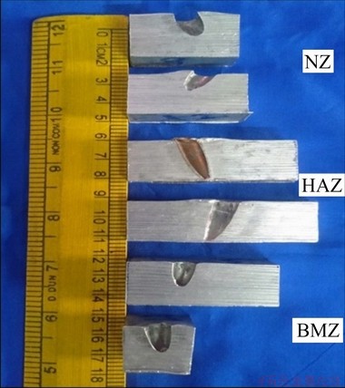
Fig. 9 Penetration channels of Al6062 backing plates after ballistic tests
The average DOP values of different heat- treated weld zones are shown in Fig. 10. It can be seen that the measured DOP values for NZ+TMAZ, HAZ and BMZ were 9.91, 21.14 and 8.46 mm, respectively. The BMZ has a slight decrease in DOP value compared to the NZ+TMAZ.
The yawed impact penetration was noticed in the backing plates due to the variation of hardness in the target plates and the maximum kinetic energy of the AP projectile absorbed by the front plate. This could be the reason for deviation of the projectile path in the backing plates. ERDEM et al [9] also noticed that the HAZ of friction-stir- welded Al7039 has the least ballistic limit when compared to the base metal and the NZ. The lower ballistic resistance in the HAZ was mainly due to thermal softening effect caused during welding. The slight reduction in ballistic performance of NZ+TMAZ was mainly due to the change of penetration mechanism from the entry to the exit crater region, whereas the penetration mechanism in the BMZ was completely ductile hole deformation.
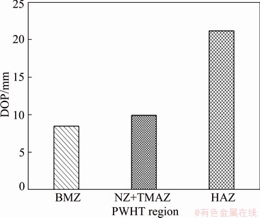
Fig. 10 DOP values of heat-treated weld zones
From the above discussion, it was observed that ballistic behaviours of the NZ+TMAZ, HAZ and BMZ were completely different. However, the crater walls of HAZ and BMZ were almost similar in appearance; whereas no such cracks were observed in the BMZ crater wall region. The deflected projectile path was noticed in the NZ+TMAZ and HAZ of the backing plate, as shown in Fig. 9. However, it was not observed in the BMZ. The variation of hardness along the transverse plane was the primary reason for the shift in the projectile path. Hence, this caused the deviation of projectile path in the backing plate. It was also noted that, in all the three regions the crater width decreased from the entry to the exit of the projectile. The least hardness value was observed in the HAZ compared to other regions which caused the increase in DOP value. It is well known that hardness is one of the important parameters that mostly influence the ballistic behaviour of a weld joint [9,21]. The DOP value of the HAZ was much higher than that of the NZ+TMAZ and BMZ.
3.4 Post-fracture SEM morphology
To investigate the fracture behaviour and failure mechanisms of targets, SEM analysis was carried out in crater region. The fracture surfaces of all three regions showed the creation of adiabatic shear bands (ASBs), especially more ASBs were observed at the entry (Fig. 11(a)). More ASBs caused the formation of cracks which in turn affected the ballistic performance. ASBs induced micro-cracks around the crater cross-section of the entry.
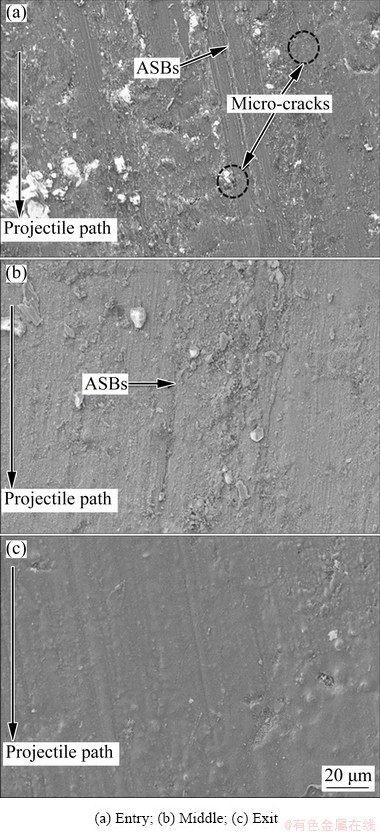
Fig. 11 SEM images of post-impact ballistic NZ-PWHT crater cross-section regions
The presence of higher ASBs lines at the entry confirms that the majority of the kinetic energy of the projectile was absorbed in this region compared to other regions which led to the deflection of projectile and restricted the penetration (Figs. 11(b) and (c)). MISHRA et al [15] found that the deflection of projectile at the target lowered the kinetic energy of the projectile, which significantly reduced the ASBs.
Figure 12 shows the SEM images of crater cross-section in different regions of HAZ-PWHT. The fracture surface of HAZ at the entry showed the presence of dimples, which indicated the failure mechanism was dominated by ductile hole enlargement and indicative of crack growth, voids and coalescence. It was also noted that all the three regions i.e. entry, middle and exit regions showed the formation of micro-cracks. Thus, one can expect the absence of ASBs and presence of cracks in HAZ when compared to NZ. The formation of cracks was due to the inability of the material to accommodate the radial stresses. The presence of micro-cracks at the entry, middle and exit was the reason for a reduction in ballistic performance. The formation of micro-cracks on the crater surface was due to the local temperature rise; hence, it may cause thermal softening effect and produce tensile stress.
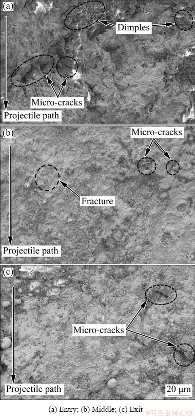
Fig. 12 SEM images of crater cross-section in different regions of HAZ-PWHT
Figure 13 shows the SEM images of crater cross-section in different regions of BMZ-PWHT. The presence of cracks at the entry of crater cross-section indicated that the penetration process was dominated by ASBs. The crater wall surfaces showed the formation of cracks at the entry and exit, and few ASBs at the middle. The presence of the shear bands in the middle of crater surface of the BMZ confirmed that the failure caused stress waves from the circumference of the specimen. The reflected stress waves contributed to the formation of ASB [25].The contact stress waves on the front face caused crack initiation and crack propagation along the thickness direction, which was indicated in the higher magnification SEM fracture images of the entry. The formation of cracks was due to lack of ability of the target to accommodate the shear strain generated by the projectile and influences of radial and tangential stress [15]. The presence of cracks on the BMZ crater surface was mainly due to the presence of coarse ��-Mg and retained spherical Mg17Al12 phase between grain boundaries that led to the initiation of cracks during the projectile penetration. However, these cracks were not observed in the surface level as discussed earlier. The small discontinuous crack was present at the exit, which indicated that the complete projectile impact energy was not transferred to the backing plate. Hence, it slightly reduced the depth of penetration compared to NZ-PWHT. Even though a larger number of ASBs were noticed in NZ compard to BMZ, its ballistic performance was not significantly inferior to that of the BMZ. From the fracture SEM images of BMZ it was understood that there was a change in fracture mode from ductile to mixed mode. In addition, the hardness of the target significantly influenced the change in ballistic failure mechanism [9,26].
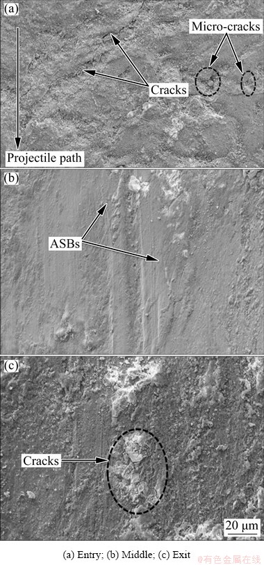
Fig. 13 SEM images of crater cross-section in different regions of BMZ-PWHT
4 Conclusions
(1) The effect of different PWHT temperatures (150, 250 and 350 ��C) on the microhardness was determined and compared with non-heat treated FSW joints. The maximum hardness value of HV 69 was obtained in the NZ under the PWHT condition of 250 ��C, 1 h, which was 7.93% and 3.03% higher than that of the NZ-FSW and BM regions, respectively.
(2) The NZ-FSW showed homogeneous microstructure with fine ��-Mg and partial dissolution of ��-Mg17Al12 phase due to stirring effect. Because of heat treatment, significant dissolution of ��-Mg17Al12 phase and strengthening of precipitated particles were noticed.
(3) Ballistic resistances of NZ+TMAZ and HAZ were 53.12% and 59.98% lower than that of the BMZ, respectively. The failure mechanism in the NZ+TMAZ was the combination of spalling and plugging. The least hardness of HAZ showed plugging failure along with surface cracks from the entry to the exit of penetration channel. The front face showed the formation of radial cracks.
(4) Post ballistic impact SEM images of NZ+TMAZ and BMZ showed the formation of ASBs and induced cracks. The crater in the HAZ exhibited micro-cracks in all three regions of the entry, middle and exit and along with ductile dimples at the entry. The HAZ region allows the projectile to enter easily and decreased the ballistic resistance when compared to other zones. The fragmentation failure was not observed in all three zones of PWHT target. Hence, PWHT process can be a suitable process for improving the hardness and ballistic resistance of FSW Mg alloy.
References
[1] JONES T L, KONDOH K. Magnesium Technology [M]. Heidelberg: Springer, 2011: 425-430.
[2] ABDULLAH M F, ABDULLAH S, OMAR M Z, SAJURI Z, SOHAIMI R M. Failure observation of the AZ31B magnesium alloy and the effect of lead addition content under ballistic impact [J]. Advances in Mechanical Engineering, 2015, 7: 1-13.
[3] DORBANE A, MANSOOR B, AYOUB G, SHUNMUGASAMY V C, IMAD A. Mechanical, microstructural and fracture properties of dissimilar welds produced by friction stir welding of AZ31B and Al6061 [J]. Materials Science and Engineering A, 2016, 651: 720-733.
[4] PADHEE C K, MASANTA M, MONDAL A K. Feasibility of Al-TiC coating on AZ91 magnesium alloy by TIG alloying method for tribological application [J]. Transactions of Nonferrous Metals Society of China, 2020, 30: 1550-1559.
[5] DERRY C G, ROBSON J D. Characterisation and modelling of toughness in 6013-T6 aerospace aluminium alloy friction stir welds [J]. Materials Science and Engineering A, 2008, 490: 328-334.
[6] THOMPSON B, DOHERTY K, NIESE C, EFF M, STOTLER T, PRAMANN Z, SEAMAN J, SPENCER R, WHITE P. Friction stir welding of thick section aluminum for military vehicle applications [C]//Proceedings of the 9th International Symposium on Friction Stir Welding, 2012. Huntsville, AL, 2012: 1-10.
[7] GRUJICIC M, ARAKERE G, HARIHARAN A, PANDURANGAN B. A concurrent product-development approach for friction-stir welded vehicle-underbody structures [J]. Journal of Materials Engineering and Performance, 2012, 21: 437-449.
[8] SULLIVAN A, ROBSON J D. Microstructural properties of friction stir welded and post-weld heat-treated 7449 aluminium alloy thick plate [J]. Materials Science and Engineering A, 2008, 478: 351-360.
[9] ERDEM M, CINICI H, GOKMEN U, KARAKOC H, TURKER M. Mechanical and ballistic properties of powder metal 7039 aluminium alloy joined by friction stir welding [J]. Transactions of Nonferrous Metals Society of China, 2016, 26: 74-84.
[10] HOLMEN J K, BORVIK T, MYHR O R, FJAER H G, HOPPERSTAD O S. Perforation of welded aluminum components: Microstructure-based modeling and experimental validation [J]. International Journal of Impact Engineering, 2015, 84: 96-107.
[11] JHA A K, SHIRESHA N, MURTY S N, DIWAKAR V, SREEKUMAR K. Ballistic impact testing of AA2219 aluminium alloy welded plates and their metallurgical characterisation [J]. Indian Journal of Engineering Material Science, 2005, 12: 221-226.
[12] JENA P K, SENTHIL P P. Effect of tempering time on the ballistic performance of a high strength armour steel [J]. Journal of Applied Research and Technology, 2016, 14: 47-53.
[13] KARAMIS M B, NAIR F E, TASDEMIRCI A. Analyses of metallurgical behavior of Al-SiCp composites after ballistic impacts [J]. Composite Structures, 2004, 64: 219-226.
[14] MONDAL C, MISHRA B, JENA P K, KUMAR K S, BHAT T B. Effect of heat treatment on the behavior of an AA7055 aluminum alloy during ballistic impact [J]. International Journal of Impact Engineering, 2011, 38: 745-754.
[15] MISHRA B, JENA P K, RAMAKRISHNA B, MADHU V, BHAT T B, GUPTA N K. Effect of tempering temperature, plate thickness and presence of holes on ballistic impact behavior and ASB formation of a high strength steel [J]. International Journal of Impact Engineering, 2012, 44: 17-28.
[16] SUKUMAR G, SINGH B B, BHATTACHARJEE A, KUMAR K S, GOGIA A K. Ballistic impact behaviour of ��-CEZ Ti alloy against 7.62 mm armour piercing projectiles [J]. International Journal of Impact Engineering, 2013, 54: 149-160.
[17] MANES A, PAGANI M, SAPONARA M, MOMBELLI D, MAPELLI C A, GIGLIO M. Metallographic characterisation of Al6061-T6 aluminium plates subjected to ballistic impact [J]. Materials Science and Engineering A, 2014, 608: 207-220.
[18] YAN Z F, ZHANG H X, DUAN J W, LIU F, WANG G L. Effect of post-weld heat treatment on mechanical characteristics of AZ31 magnesium alloy welded joints [J]. Journal of Wuhan University of Technology: Mater Sci Ed, 2017, 32: 1205-1212.
[19] SIVARAJ P, KANAGARAJAN D, BALASUBRAMANIAN V. Effect of post weld heat treatment on tensile properties and microstructure characteristics of friction stir welded armour grade AA7075-T651 aluminium alloy [J]. Defence Technology, 2014, 10: 1-18.
[20] WANG G, YAN Z, ZHANG H, ZHANG X, LIU F, WANG X, SU Y. Improved properties of friction stir-welded AZ31 magnesium alloy by post-weld heat treatment [J]. Materials Science and Technology, 2017, 33: 854-863.
[21] SULLIVAN A, DERRY C, ROBSON J D, HORSFALL I, PRANGNELL P B. Microstructure simulation and ballistic behaviour of weld zones in friction stir welds in high strength aluminium 7xxx plate [J]. Materials Science and Engineering A, 2011, 528: 3409-3422.
[22] TUZ L, KOLODZIEJCZAK P, KOLASA A. Structure of butt joint of as-cast magnesium alloys [J]. Welding International, 2016, 30: 43-47.
[23] FREENEY T A, MISHRA R S. Effect of friction stir processing on microstructure and mechanical properties of a cast-magnesium�Crare earth alloy [J]. Metallurgical and Materials Transactions A, 2010, 41: 73-84.
[24] BAGHERI B, ABBASI M, ABDOLLAHZADEH A, MIRSALEHI SE. Effect of second-phase particle size and presence of vibration on AZ91/SiC surface composite layer produced by FSP [J]. Transactions of Nonferrous Metals Society of China, 2020, 30: 905-916.
[25] SINGH R K, SHARMA C, DWIVEDI D K, MEHTA N K, KUMAR P. The microstructure and mechanical properties of friction stir welded Al-Zn-Mg alloy in as welded and heat treated conditions [J]. Materials & Design, 2011, 32: 682-687.
[26] JENA P K, MISHRA B, KUMAR K S, BHAT T B. An experimental study on the ballistic impact behavior of some metallic armour materials against 7.62 mm deformable projectile [J]. Materials & Design, 2010, 31: 3308-3316.
�ȴ��������Խ���Ħ��þ�Ͻ��ͷ��������Ϊ��Ӱ��
S. DHARANI KUMAR1, S. SURESH KUMAR2
1. Department of Mechanical Engineering, Sri Eshwar College of Engineering, Coimbatore, 641202, Tamil Nadu, India;
2. Department of Mechanical Engineering, Sri Sivasubramaniya Nadar College of Engineering, Chennai, 603110, Tamil Nadu, India
ժ Ҫ�����ý���Ħ����(FSW)�����Ʊ�AZ31Bþ�Ͻӽ�ͷ�����ڲ�ͬ�����½����ȴ������о�AZ31Bþ�Ͻ��ȴ���(PWHT)��ͬ����Ŀ�����Ϊ��ʹ��7.62 mm �� 39 mm ����������ٶ�Ϊ(430��20) m/s�������ȴ���ǰ�����Ħ������ͷ����Ӳ�ȡ����������PWHT����(250 ��C, 1 h)������ȴ��������Ħ������ͷ����Ӳ�ȡ�ɨ��羵(SEM)�����ʾ���ȴ���ʹ��-Mg����ϸ�����γ�ϸС�������࣬ʹ��-Mg17Al12���ܽMg�����С�ͨ������(DOP)��������PWHT ��ͬ����Ŀ�����Ϊ���ȴ������ͷĸ����(BMZ)��DOPֵ��С�����������Ե����ܱ�3������ĺ�������SEM�������۲쵽���ȼ��д�(ASB)���γɡ�
�ؼ��ʣ�AZ31Bþ�Ͻ𣻺����ȴ�����������Ϊ��������ȼ��д�
(Edited by Wei-ping CHEN)
Corresponding author: S. SURESH KUMAR; E-mail: sureshkumars@ssn.edu.in
DOI: 10.1016/S1003-6326(20)65484-X
1003-6326/ 2021 The Nonferrous Metals Society of China. Published by Elsevier B.V. & Science Press
Abstract: Ballistic behaviour of different zones of post-weld heat-treated (PWHT) magnesium alloy (AZ31B) target against 7.62 mm �� 39 mm armour-piercing (AP) projectile with a striking velocity of (430��20) m/s was determined. Magnesium alloy (AZ31B) welded joints were prepared by using friction stir welding (FSW) process and subjected to different heat treatment conditions. The microhardness values of non-heat-treated and heat-treated FSW joints were investigated. The results indicated that PWHT process (250 ��C, 1 h) has improved the microhardness of heat-treated FSW joints. Scanning electron microscope (SEM) microstructure showed that heat treatment has caused the formation of fine ��-Mg grains and tiny precipitates and made the dissolution of ��-Mg17Al12 phase into the Mg matrix. The ballistic behaviour of PWHT zones was estimated by measuring the depth of penetration (DOP) of the projectile. Lower DOP value was observed for the base metal zone (BMZ) of a heat-treated welded joint. Post ballistic SEM examinations on the cross-section of all three zones of crater region showed the formation of adiabatic shear band (ASB).
[1] JONES T L, KONDOH K. Magnesium Technology [M]. Heidelberg: Springer, 2011: 425-430.
" target="blank">[26] JENA P K, MISHRA B, KUMAR K S, BHAT T B. An experimental study on the ballistic impact behavior of some metallic armour materials against 7.62 mm deformable projectile [J]. Materials & Design, 2010, 31: 3308-3316.
