
Trans. Nonferrous Met. Soc. China 26(2016) 3196-3204
Effect of Fe content on microstructure and mechanical properties of Cu-Fe-based composite coatings by laser induction hybrid rapid cladding
Sheng-feng ZHOU1, Jian-bo LEI1, Zheng XIONG2, Jin-bo GUO1, Zhen-jie GU1, Hong-bo PAN3
1. Laser Technology Institute, Tianjin Polytechnic University, Tianjin 300387, China;
2. School of Science, Naval University of Engineering, Wuhan 430033, China;
3. Engineering Research Institute, Anhui University of Technology, Ma��anshan 243002, China
Received 4 November 2015; accepted 28 June 2016
Abstract:
To select the proper composition and obtain an overall material-microstructure-property relationship for Cu-Fe alloy, the effect of Fe content on microstructure and properties of Cu-Fe-based composite coatings by laser induction hybrid rapid cladding was investigated. Microstructure characterization of the composite coatings was tested utilizing SEM, XRD and EDS. Microhardness measurement was executed to evaluate the mechanical properties of the composite coatings. The results show that for low Fe content, the composite coating presents a feature that Fe-rich equiaxed dendrites are embedded in the Cu-rich matrix. With increasing Fe content, the Fe-rich particles are dispersed in the Cu-rich matrix. With further increasing Fe content, large amounts of Cu-rich particles are homogeneously dispersed in the interdendrite of the Fe-rich matrix. Correspondingly, the average microhardness of the composite coatings increases gradually with the increase of Fe content and the microhardness of Cu14.5Fe83Si2C0.5 coating is much twice higher than that of the substrate.
Key words:
composite coating; laser induction hybrid rapid cladding; Cu-Fe alloy; liquid phase separation; microstructure; mechanical properties;
1 Introduction
Due to many unique properties for various industrial applications, immiscible alloys with a metastable miscibility gap are the ideal materials to produce the in-situ particles reinforced metal-matrix composites (MMCs) [1-3]. Especially, when the fine Fe-rich particles are uniformly embedded in the Cu-rich matrix, the Cu-Fe alloys exhibit many excellent properties such as large ductility, enhanced hardness and excellent soft magnetic performance, which have received extensive attention [4-6]. Due to two liquid phases having different densities within the miscibility gap, the Cu-Fe alloys prepared by the conventional solidification techniques, such as electromagnetic levitation and drop tube [5,6], have serious constituent segregation prior to solidification, complex and expensive process, which have however limited their potential applications [7]. To overcome this drawback, the drop tube facility [8] and the rapid solidification techniques such as high-pressure gas atomization [9,10] and laser cladding [11] have many advantages in manufacturing the Cu-Fe alloys with desired microstructures, such as microstructure refinement, extension of solid solubility, or formation of non-equilibrium phases [12].
Summing up the previous results [8-16], it is found that the microstructure of the immiscible alloys with a miscibility gap depends on four factors of chemical composition, undercooling, cooling rate and fluid flow (i.e., the velocity of Marangoni and Stokes motions) during the rapid solidification. Therefore, the previous studies mainly focused on controlling the solidification conditions of Cu-Fe alloys to obtain the proper solidification microstructure. In particular, close attention has been paid to the influence of undercooling on the microstructure evolution of Cu-Fe alloys for investigating the microstructure characteristics and solidification process during the liquid phase separation [17,18].
In our previous work, the crack-free Cu-Fe-based composite coatings were produced by laser induction hybrid rapid cladding (LIHRC) on copper alloy [19-21]. Although the microhardness of coating is much three times higher than that of copper alloy, the ��delamination phenomenon�� (i.e., the spherical Fe-rich particles are embedded in Cu-rich matrix in the center of coating, while the spherical Cu-rich particles are distributed in the interdendritic region of ��-Fe at the top of coating [19]) occurs. However, the formation mechanism of Cu-Fe- based composite coatings by LIHRC has not been understood clearly, and an overall material- microstructure-property relationship is still lacking. In this work, the formation mechanism of Cu-Fe-based composite coatings was investigated at different Fe contents. Additionally, an attempt was made to establish the relationships between Fe content, microstructure characteristics and properties of Cu-Fe-based composite coatings by LIHRC, and provide guidance for selecting the proper composition of the Cu-Fe immiscible alloys.
2 Experimental
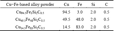
AISI 1050 carbon steel with dimensions of 100 mm �� 50 mm �� 6 mm was used as the substrate material, whose chemical composition was (mass fraction): 0.55% C, 0.9% Mn, 0.04% S, 0.05% P and balance Fe. The Cu-Fe-based powders with sizes of 30-50 ��m were used as the cladding material and the chemical composition is listed in Table 1.
Table 1 Chemical composition of Cu-Fe-based alloy powder (mass fraction, %)
The HGL-JKR5080 5 kW continuous wave CO2 laser was used together with a high frequency induction heater of integrated module in experiments. The laser beam interacted with the source of induction heating on the surface of substrate to form a heating source of LIHRC. The schematic image for Cu-Fe-based composite coatings produced by LIHRC was shown in detail in our previous work [19]. Moreover, the beam spot was adjusted into the elliptical spot with an optical adjustment device. The major and minor axes of laser beam were 7 and 5 mm, respectively. The major axis was parallel to the direction of laser scanning speed. The laser power was 5 kW. The laser scanning speed was 2200 mm/min. The average temperature of substrate by LIHRC was set at 973 K by adjusting the power of induction heater. The powder feeding rate was 73.5 g/min. Pure Ar gas (99.99%) was used to blow the Cu-Fe-based powders into the molten pool. The angle between the powder nozzle and the substrate was set at 53��. The large area coatings were produced by multi- track and multi-layer LIHRC. The overlapping rate was 45% and the dimensions of coatings were 100 mm �� 40 mm �� 2 mm.
After LIHRC, the cross-sections of coatings were cut and polished by standard metallographic techniques. The polished samples were etched by a solution consisting of 4 g FeCl3, 12 mL HCl and 100 mL H2O. The microstructure of coatings was observed by scanning electron microcopy (SEM) with energy dispersive spectrometry (EDS) (Model Quanta 200, FEI, Holland). The microhardness of coatings was measured using a hardness tester (Model HVS-1000 digital displayer microhardness tester, China) with a load of 1.96 N and a load time of 20 s.
3 Results
3.1 Microstructure characteristics of coatings
Figure 1 shows the microstructures of Cu94.5Fe3- Si2C0.5 coating by LIHRC. The microstructure is characterized by planar growth with a thickness of 3-5 ��m, followed by the columnar dendrites at the coating-substrate interface (Fig. 1(a)). In the center and at the top of coating, large amounts of fine equiaxed dendrites are embedded in the matrix (Figs. 1(b) and (c)). Their magnified metallographic image is shown in Fig. 1(d). These fine equiaxed dendrites are considered as the Fe-rich phase but their compositions are accurately determined by EDS analysis due to their small dimensions. ZHANG et al [4] also reported the similar characteristics of the Cu-35%Fe (mass fraction) alloys prepared by melt-fluxing in combination with cyclic superheating technique.
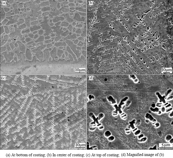
Fig. 1 Microstructures of Cu94.5Fe3Si2C0.5 coating by LIHRC
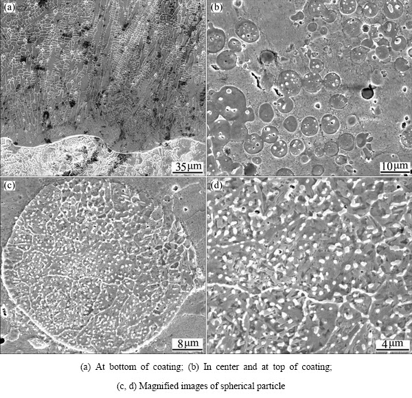
Fig. 2 Microstructures of Cu49.5Fe48Si2C0.5 coating by LIHRC
Figure 2 shows the microstructures of Cu49.5Fe48- Si2C0.5 coating by LIHRC. The planar growth is not observed at the coating-substrate interface (Fig. 2(a)), which is different from Cu94.5Fe3Si2C0.5 coating. This is presumably because the thickness of plane growth is smaller than the resolution limit of SEM. The gray dendrites and white interdendritic phases are observed with increasing distance from the interface of coating and substrate. The dendrite consists of 67.6% Fe, 27.9% Cu and 4.5% Si. Obviously, the dendrite is Fe-rich phase containing a supersaturated Cu. In the center and at the top of coating, many spherical particles with diameters in the range from 2 to 10 ��m are embedded in the matrix (Fig. 2(b)) and large amounts of white nanostructured grains are precipitated inside the spherical particles (Figs. 2(c) and (d)). EDS analysis indicates that the spherical particle contains 87.9% Fe, 9.8% Cu and 2.3% Si and the matrix contains 92.5% Cu, 4.5% Fe and 3.0% Si, showing that the spherical Fe-rich particles are embedded in the Cu-rich matrix. The white nanostructured grains can be the Cu-rich phases but their compositions cannot be accurately determined by EDS analysis due to their small dimensions [10].
Figure 3 shows the microstructures of Cu14.5Fe83- Si2C0.5 coating by LIHRC. A fusion line is formed at the coating-substrate interface. The dendrites and the spherical particles are observed after a certain growth distance (Fig. 3(a)). In the center and at the top of coating, large amounts of smaller spherical particles are dispersedly distributed in the interdendrite of metal matrix (Figs. 3(b) and (c)). EDS analysis indicates that the dendrite contains 82.3% Fe, 12.6% Cu and 5.1% Si (mass fraction), and that the spherical particle is composed of 94.8% Cu, 4.2% Fe and 1.0% Si. This illustrates that the dendrite is Fe-rich phase containing a supersaturated Cu, while the spherical particle is Cu-rich phase containing a supersaturated Fe.
In summary, the results of XRD combined EDS analysis on the above-mentioned three types of composite coatings indicated that the composite coatings were mainly composed of ��-Cu and ��-Fe phases. When the Fe content was lower in Cu-Fe-based powder, the relative intensities of the diffraction peaks corresponding to ��-Cu in the composite coating were clearly higher compared with those of ��-Fe phase. Obviously, the fine dendrites or the Fe-rich particles identified as ��-Fe were embedded in the ��-Cu matrix. However, when the Fe content was increased to 83% (mass fraction) in Cu-Fe-based powder, the diffraction peak of ��-Fe phase with a higher intensity was obtained in the composite coating. Clearly, the Cu-rich particles identified as ��-Cu were distributed in the ��-Fe matrix.
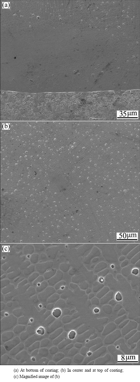
Fig. 3 Microstructures of Cu14.5Fe83Si2C0.5 coating by LIHRC
3.2 Microhardness of Cu-Fe-based composite coatings
Figure 4 shows the microhardness of different zones including cladding zone (CZ), heat-affected zone (HAZ) and substrate (SUB). With the increase of Fe content, the average microhardness of CZ increases from HV0.2 263.4 to HV0.2 360.3. For Cu14.5Fe83Si2C0.5 coating, the microhardness of HAZ is the highest (HV0.2 298). This is because the microstructure of HAZ is mainly composed of lath martensite, as shown in Fig. 5. Moreover, the microhardness of coating reaches a maximum value of HV0.2 381, which is much twice higher than that of SUB (HV0.2 175). The results indicate that Fe content has an obvious influence on the microhardness of Cu-Fe-based coating by LIHRC.
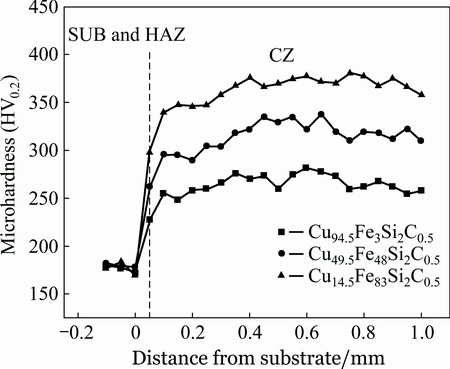
Fig. 4 Microhardness distribution of Cu-Fe-based coatings by LIHRC
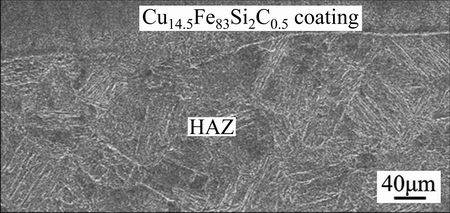
Fig. 5 Microstructure of HAZ on surface of carbon steel substrate
4 Discussion
The ��delamination phenomenon�� [19] does not occur in the above three kinds of Cu-Fe-based composite coatings by LIHRC. When Fe content is only 3.0% (mass fraction), large amounts of fine Fe-rich equiaxed dendrites are embedded in the Cu-rich matrix (Figs. 1(b) and (c)). Apparently, the liquid phase separation does not occur during LIHRC. When Fe content increases to 48.0% (mass fraction), the microstructure is characterized by two aspects. Firstly, many spherical Fe-rich particles are embedded in the Cu-rich matrix and most of them connect with each other (Fig. 2(b)). Secondly, large amounts of nanostructured Cu-rich grains precipitate inside the spherical Fe-rich particles (Fig. 2(c)). When Fe content further increases to 83.0% (mass fraction), large amounts of spherical Cu-rich particles are embedded in the interdendrite of Fe-rich matrix (Figs. 3(b) and (c)). According to the binary phase diagram of Cu-Fe alloy with the metastable miscibility gap above 900 K (Fig. 6) [22], the liquid phase separation takes place during LIHRC with increasing Fe content.
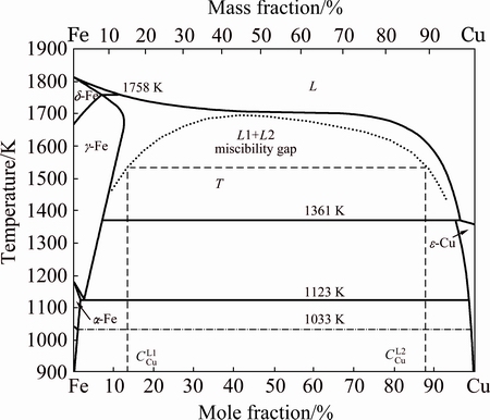
Fig. 6 Phase diagram of Cu-Fe system showing existence of metastable miscibility gap above 900 K [22]
Although the substrate is preheated by induction heater to decrease the temperature gradient between coating and substrate, LIHRC is still a rapid solidification process. For a simply qualitative analysis, G is the temperature gradient and can be calculated as follows [23]:
 (1)
(1)
where T is the liquidus temperature of the alloy; T0 is the preheated temperature of the substrate; K is the thermal conductivity; P is the laser power and �� is the laser absorption coefficient. The previous results show that solidification rate R is in the order of the laser scanning speed vs [24]. Under the present conditions, the calculated G is ~753 K/mm and the cooling rate is ~2.7��104 K/s (��=10%, K=180 W/(m��K)). Such high cooling rate can refine the microstructure of Cu-Fe coatings significantly. According to the solidification speed distribution along the depth of the molten pool in a laser track described by GREMAUD et al [25], the solidification firstly takes place, in all cases, with a planar front from the bottom of molten pool after laser melting. Moreover, solidification rate R equals zero at the bottom of molten pool and increases towards the surface of molten pool. However, temperature gradient G is the highest at the bottom and decreases gradually towards the top of molten pool. The characteristics of crystal growth depends on the extent of constitutional undercooling ahead of the solidification interface, while the extent of constitutional undercooling is related to the ratio of temperature gradient G to solidification rate R. Solidification rate R increases and temperature gradient G decreases from the bottom to the top of the track. A constitutional undercooling is soon generated. As a consequence, the planar solid/liquid interface becomes unstable. Additionally, the contents of alloy elements (Fe, Cu and Si) near the interface of substrate and molten pool are lower due to insufficient time for mixing and diffusion. This leads to the formation of fine Cu-rich dendrites containing a supersaturated Fe (Fig. 1(a)) or fine Fe-rich dendrites containing a supersaturated Cu (Figs. 2(a) and 3(a)).
High cooling rate easily induces the dynamic undercooling [13]. The molten Cu-Fe alloy is readily undercooled into the immiscible gap during LIHRC, which in turn results in the liquid phase separation. However, the liquid phase separation does not occur in Cu94.5Fe3Si2C0.5 coating. This is because the liquid phase separation in Cu-Fe alloy depends not only on the undercooling, but also on the chemical composition [13]. When Cu94.5Fe3Si2C0.5 powder is melted during LIHRC, ��-Fe is transformed into ��-Fe due to high undercooling. Subsequently, ��-Fe with relatively high melting point firstly is solidified and transformed into Fe-rich dendrites in a partitionless manner during the rapid solidification. Meanwhile, the grown ��-Fe dendrites are broken apart into many smaller ��-Fe dendrites by the convection and stirring, which is driven by the difference in surface tension of the melt between the center and the edge of molten pool [17,26]. Subsequently, these smaller ��-Fe dendrites are transformed into fine Fe-rich dendrites and the Cu-rich melt is changed into the Cu-rich matrix after the rapid solidification. Due to liberation of latent heat of crystallization from the solidification of the Cu-rich melt, the grown ��-Fe dendrites are remelted by recalescence, which in turn results in multiple heterogeneous nucleation events. As a result, large amounts of fine Fe-rich equiaxed dendrites containing a supersaturated Cu are enveloped by the Cu-rich matrix containing a supersaturated Fe due to the enhanced solute trapping during LIHRC (Figs. 1(b) and (c)).
When Fe content increases to 48.0% (mass fraction), the microstructure of coating is characterized by the appearance of spherical Fe-rich particles, implying that Cu-Fe-based coating is solidified within the miscibility gap and the liquid phase separation occurs prior to the crystallization during LIHRC. Once the undercooling exceeds the separation undercooling for entering the miscibility gap, the liquid phase separation occurs [13]. Therefore, the undercooled Cu49.5Fe48Si2C0.5 alloy melt is separated into two melts: one is Cu-rich melt (L1) as the major phase and the other is Fe-rich melt (L2) as the minor phase. To keep the minimum interfacial energy, the Fe-rich melt as the minor phase shrinks into the Fe-rich droplets. These Fe-rich droplets are firstly solidified to form the spherical Fe-rich particles due to higher melting point. The Cu-rich melt is solidified at the boundary finally to form the Cu-rich matrix. Furthermore, the recalescence induced by the liberation of latent heat of crystallization from the solidification of the Cu-rich melt can remelt the Fe-rich particles and increase their liquidus temperature, leading to a decrease in separation undercooling of the Fe-rich melt [11]. As a result, large amounts of fine Cu-rich grains are precipitated inside the spherical Fe-rich particles (Figs. 2(c) and (d)) due to the secondary liquid separation.
It is noted that some spherical Fe-rich particles connect with each other (Fig. 2(b)), showing that the Fe-rich droplets can impinge and coalesce to form larger droplets. When there is an interfacial tension gradient between the spherical droplet and the matrix liquid phase, the droplets move toward the region with lower interfacial energy due to Marangoni motion, whose velocity is described as follows [27]:
 (2)
(2)
where r is the radius of the droplet, ��d and ��m are the viscosities of the droplet and the matrix liquid phase, respectively,  ��/T is the gradient of the interfacial energy between the droplet and the matrix liquid phase as a function of temperature (T=1550 K, ��/T= 0.5��10-3 J/m2 [28]), and G is the temperature gradient.
Moreover, the droplet is also driven by the gravity effect and its velocity is described by Stokes equation [28]:
 (3)
(3)
where g is the gravity coefficient and ���� is the difference of density between the droplet and the matrix liquid phase.
According to Eqs. (2) and (3), the coefficient of competitive movement, M, is defined as the ratio of vm to vs. The viscosity of the Fe-rich liquid estimated is 8.46��10-3 Pa��s and the viscosity of the Cu-rich liquid estimated is 2.29��10-3 Pa��s. The relationship between the coefficient of competitive movement and the radius of the droplet is shown in Fig. 7. Clearly, the coefficient of competitive movement decreases markedly with an increase in radius of the droplet. When the coefficient of competitive movement is approximately equal to 1, the radius of the droplet is defined as the critical radius. It can be seen that the critical radius of the Fe-rich droplet (i.e., 10 ��m) is much smaller than that of the Cu-rich droplet (i.e., 36 ��m). Moreover, with an increase in temperature gradient, the coefficient of competitive movement increases markedly under the same radius of the droplet, showing that the gravity field plays a minor role in the movement of the droplet. Therefore, the smaller critical radius of the droplet can be obtained when the temperature gradient is decreased. It was beneficial to the homogeneous distribution of the spherical Cu-rich or Fe-rich particles in the Fe-rich or Cu-rich matrix.
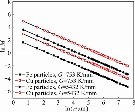
Fig. 7 Relationship between coefficient of competitive movement M and radius of droplet
At the beginning of Fe-rich droplet formation in Cu49.5Fe48Si2C0.5 system, the radius is smaller than the critical radius. The movement of Fe-rich droplets is mainly from Marangoni motion in the Cu-rich melt. These Fe-rich droplets move not only relatively to the Cu-rich matrix but also relatively to each other due to fluid flow. When the droplets move so closely and collide with each other, the new droplets with larger size are formed. This leads to high chemical potential gradient which induces a violent hydrodynamic flow around larger droplets to restore the equilibrium shape by the solute diffusion. Nevertheless, the solute diffusion cannot follow this rapid coarsening process. This leads to a strong temporal diffusion field around the larger droplet and induces the attractive interactions between the droplets [29]. This in turn results in the subsequent collision by which the droplets grow up rapidly. This coarsening process between the droplets is called as a ��gradient-induced-coupling mechanism�� [30]. Certainly, with an increase in the radius of Fe-rich particles, the coefficient of competitive movement is decreased and the effect of gravity field becomes significant. The Fe-rich droplets can stop moving toward the top of molten pool when the radius of the Fe-rich droplet is larger than the critical radius. Additionally, many smaller Fe-rich droplets are transformed into the smaller spherical Fe-rich particles because they have no enough time to be merged by those grown Fe-rich droplets. As a result, they are preserved around those larger Fe-rich particles which connect with each other and are frozen in the Cu-rich matrix during the rapid solidification (Fig. 2(b)).
In contrast, the undercooled Cu14.5Fe83Si2C0.5 alloy melt can be separated into two melts: one is Cu-rich melt (L1) as the minor phase and the other is Fe-rich melt (L2) as the major phase. To keep the minimum interfacial energy, the Cu-rich melt as the minor phase shrinks into the Cu-rich droplets. Although the Cu-rich droplets in Cu14.5Fe83Si2C0.5 system have a larger critical radius compared with the Fe-rich droplets in Cu49.5Fe48Si2C0.5 system (Fig. 7), the Cu-rich particles do not aggregate and the coarsening Cu-rich particles are not observed (Figs. 3(b) and (c)). This is explained by the following reasons. According to Tanaka��s analysis [30], the concentration gradient within the Fe-rich matrix liquid phases can result in a gradient tension ��G which can minimize the total length of the gradient zone within the Fe-rich matrix liquid phases. If the interfacial tension between the Fe-rich liquid matrix and the Cu-rich droplet ��L1-L2, the droplets can collide and coalesce. However, there is nearly no increase in the diameter of Cu-rich particles, suggesting that the tension gradient ��G is far less than the interface tension ��L1-L2. Moreover, the solidification temperature of Fe-rich melt is much higher than that of Cu-rich droplets. The Fe-rich melt as the major phase is firstly solidified and takes on the typical characteristic of dendrites, which also prevents the Cu-rich droplets from colliding and merging reciprocally. The Cu-rich droplets as the minor phases can also hinder the Fe-rich dendrites from further growing during the rapid solidification. Due to high cooling rate, the Cu-rich droplets have no enough time to carry out the direct collision by the diffusion coupling and are frozen in the interdendrite of Fe-rich matrix. As a result, many smaller Cu-rich particles with diameters in the range from 2 to 5 ��m are formed (Figs. 3(b) and (c)).
Cu14.5Fe83Si2C0.5 coating has a higher micro- hardness, as shown in Fig. 4. This is explained by the following reasons. Firstly, large amounts of smaller spherical Cu-rich particles are homogeneously embedded in the Fe-rich interdendrites to block the dislocation migration, resulting in dispersion strengthening. Secondly, the Fe-rich matrix contains a supersaturated Cu, resulting in solid solution strengthening. Thirdly, the spherical Cu-rich particles can block the Fe-rich dendrites from growing up to gain the fine-grain strengthening due to high cooling rate. The strengthening mechanism for Cu14.5Fe83Si2C0.5 coating is the combination of the solid-solution strengthening, the dispersion strengthening and the fine grain strengthening. As a result, Cu14.5Fe83Si2C0.5 coating has a higher microhardness compared with other two kinds of Cu-Fe-based composite coatings.
5 Conclusions
1) With the increase of Fe content, the microstructure of Cu-Fe-based coating is characterized by a transition from the Fe-rich equiaxed dendrites embedded in the Cu-rich matrix, the Fe-rich particles dispersed in the Cu-rich matrix to the Cu-rich particles dispersed in the interdendritic zone of Fe-rich matrix. Moreover, large amounts of nanostructured Cu-rich grains are precipitated inside the spherical Fe-rich particles in Cu49.5Fe48Si2C0.5 coating. The ��delamination phenomenon�� does not occur in Cu-Fe-based composite coatings.
2) The microhardness of Cu-Fe-based composite coatings by LIHRC significantly depends on the chemical composition and the microstructure characteristics of coatings. With the increase of Fe content, the average microhardness of Cu-Fe-based composite coatings increases. The microhardess of Cu14.5Fe83Si2C0.5 coating is much twice higher than that of carbon steel substrate.
References
[1] SUN Zhan-bo, WANG You-hong, GUO Juan. Liquid phase separation of Cu-Cr alloys during rapid cooling [J]. Transactions of Nonferrous Metals Society of China, 2006, 16(5): 998-1002.
[2] YANG Gen-cang, XIE Hui, HAO Wei-xin, ZHANG Zhong-ming, GUO Xue-feng. Liquid-liquid phase separation in highly undercooled Ni-Pb hypermonotectic alloys [J]. Transactions of Nonferrous Metals Society of China, 2006, 16(2): 290-293.
[3] GUO Jin-bo, CAO Chong-de, GONG Su-lian, SONG Rui-bo, BAI Xiao-jun, WANG Jian-yuan, ZHENG Jian-ban, WEN Xi-xing, SUN Zhan-bo. Rapid solidification of Cu60Co30Cr10 alloy under different conditions [J]. Transactions of Nonferrous Metals Society of China, 2013, 23(3): 731-734.
[4] ZHANG J, CUI X, YANG Y, WANG Y. Solidification of the Cu-35wt pct Fe alloys with liquid separation [J]. Metallurgical and Materials Transactions A, 2013, 44(12): 5544-5548.
[5] LUO S B, WANG W L, CHANG J, XIA Z C, WEI B. A comparative study of dendritic growth within undercooled liquid pure Fe and Fe50Cu50 alloy [J]. Acta Materialia, 2014, 69(5): 355- 364.
[6] LU X, CAO C, WEI B. Microstructure evolution of undercooled iron-copper hypoperitectic alloy [J]. Materials Science and Engineering A, 2001, 313(1-2): 198-206.
[7] FU L, YANG J, BI Q, LIU W. Combustion synthesis immiscible nanostructured Fe-Cu alloy [J]. Journal of Alloys and Compounds, 2009, 482(1-2): L22-L24.
[8] LUO Bing-chi, WANG Hai-peng, WEI Bing-bo. Rapid solidification of ternary Ni-Pb-Cu monotectic alloy under free fall conditions [J]. The Chinese Journal of Nonferrous Metals, 2009, 19(2): 279-285. (in Chinese)
[9] HE J, ZHAO J, RATKE L. Solidification microstructure and dynamics of metastable phase transformation in undercooled liquid Cu-Fe alloys [J]. Acta Materialia, 2006, 54(7): 1749-1757.
[10] ZHAO J. Formation of the minor phase shell on the surface of hypermonotectic alloy powders [J]. Scripta Materialia, 2006, 54(2): 247-250.
[11] CHEN Shu, ZHAO Jiu-zhou. Solidification of monotectic alloy under laser surface treatment conditions [J]. Acta Metallurgica Sinica, 2013, 49(5): 537-543. (in Chinese)
[12] ZHANG Lin, WANG En-gang, ZUO Xiao-wei, HE Ji-cheng. Effect of magnetic field on liquid-liquid separation of Cu-Pb-La hypermonotectic alloy [J]. Rare Metal Materials and Engineering, 2015, 44(2): 344-348. (in Chinese)
[13] MUNITZ A, VENKERT A, LANDAU P, KAUFMAN M J, ABBASCHIAN R. Microstructure and phase selection in supercooled copper alloys exhibiting metastable liquid miscibility gaps [J]. Journal of Materials Science, 2012, 47(23): 7955-7970.
[14] ZHU Ding-yi, YANG Xiao-hua, HAN Xiu-jun, WEI Bing-bo. Rapid solidification microstructures of Fe-Sn monotectic alloys at deep undercooling [J]. The Chinese Journal of Nonferrous Metals, 2003, 13(2): 328-334. (in Chinese)
[15] SUN Qian, JIANG Hong-xiang, ZHAO Jiu-zhou. Effect of micro-alloying element Bi on solidification and microstructure of Al-Pb alloy [J]. Acta Metallurgica Sinica, 2016, 52(4): 497-504. (in Chinese)
[16] HE J, ZHAO J. Behavior of Fe-rich phase during rapid solidification of Cu-Fe hypoperitectic alloy [J]. Materials Science and Engineering A, 2005, 404(1-2): 85-90.
[17] LIU N. Investigation on the phase separation in undercooled Cu-Fe melts [J]. Journal of Non-Crystalline Solids, 2012, 358(2): 196-199.
[18] CHEN Y, LIU F, YANG G, XU X, ZHOU Y. Rapid solidification of bulk undercooled hypoperitectic Fe-Cu alloy [J]. Journal of Alloys and Compounds, 2007, 427(1-2): L1-L5.
[19] ZHOU Sheng-feng, DAI Xiao-qin, XIONG Zheng, ZHANG Tian-you, WU Chao. Microstructure and property of Cu-Fe alloy coating prepared by laser-induction hybrid cladding [J]. The Chinese Journal of Nonferrous Metals, 2014, 24(7): 1812-1816. (in Chinese)
[20] ZHOU S, DAI X, XIONG Z, WU C, ZHANG T. Influence of Al addition on microstructure and properties of Cu-Fe-based composite coatings by laser induction hybrid rapid cladding [J]. J Materials Research, 2014, 29(7): 865-873.
[21] ZHOU S, WU C, ZHANG T, ZHANG Z. Carbon nanotube- and Fep-reinforced copper-matrix composites by laser induction hybrid rapid cladding [J]. Scripta Materialia, 2014, 76(4): 25-28.
[22] CHEN Q, JIN Z P. The Fe-Cu system: A thermodynamic evaluation [J]. Metallurgical and Materials Transactions A, 1995, 26(2): 417-426.
[23] Rosenthal D. The theory of moving source of heat and its application to metal transfer [J]. Transaction of ASME, 1946, 43: 849-866.
[24] PEI Y T, de HOSSON J T M. Functionally graded materials produced by laser cladding [J]. Acta Materialia, 2000, 48(10): 2617-2624.
[25] Gremaud M, Carrard M, Kurz M. The microstructure of rapid solidified Al-Fe alloys subjected to laser surface treatment [J]. Acta Materialia, 1990, 38(12): 2587-2599.
[26] WANG C P, LIU X J, OHNUMA I, KAINUMA R, Ishida K. Formation of core-type macroscopic morphology in Cu-Fe base alloy with liquid miscibility gap [J]. Metallurgical and Materials Transactions A, 2004, 35(4): 1243-1253.
[27] Young N O, Goldstein J S, BLOCK M J. The motion of bubbles in a vertical temperature gradient [J]. Journal of Fluid Mechanics, 1959, 6(3): 350-356.
[28] WANG C P, LIU X J, OHNUMA I, KAINUMA R, Ishida K. Formation of immiscible alloy powders with egg-type microstructure [J]. Science, 2002, 297(5583): 990-993.
[29] SHI R P, WANG C P, WHEELER D, LIU X J, WANG Y. Formation mechanisms of self-organized core/shell and core/shell/corona microstructures in liquid droplets of immiscible alloys [J]. Acta Materialia, 2013, 61(4): 1229-1243.
[30] TANAKA H. A new coarsening mechanism of droplet spinodal decomposition [J]. Journal of Chemical Physics, 1995, 103(6): 2361-2364.
�������Լ��⣭��Ӧ���Ͽ����۸�ͭ����������Ϳ������֯����ѧ���ܵ�Ӱ��
��ʥ��1������1���� ��2������1�������1���˺鲨3
1. ���ҵ��ѧ ���⼼���о�������� 300387��
2. �������̴�ѧ ��ѧԺ���人 430033��
3. ���չ�ҵ��ѧ �����о�Ժ������ɽ 243002
ժ Ҫ��Ϊ�˸�ͭ�����Ͻ�ѡ����ʵĻ�ѧ�ɷ��Լ��������ϣ�����֯������֮��Ĺ�ϵ���о����������Լ��⣭��Ӧ���Ͽ����۸�ͭ����������Ϳ������֯�����ܵ�Ӱ�졣����ɨ��羵��X���������������������ײ����˸���Ϳ�������֯��������Ӳ����������Ϳ�����ѧ���ܡ������������ͭ������ĩ�е��������ϵ�ʱ������Ϳ����и�������֦��������������������Ƕ�ڸ�ͭ�����ڣ����������������ӣ�����������ɢ�ֲ��ڸ�ͭ�����ڣ������������Ľ�һ�����ӣ�������ͭ������ɢ�ֲ��ڸ����������֦���䡣��ˣ�����ͭ������ĩ�������������ӣ�����Ϳ���ƽ����Ӳ�������ӣ���Cu14.5Fe83Si2C0.5Ϳ�����Ӳ���ǻ��ĵ������ࡣ
�ؼ��ʣ�����Ϳ�㣻���⣭��Ӧ���Ͽ����۸���ͭ�����Ͻ�Һ����룻����֯����ѧ����
(Edited by Wei-ping CHEN)
Foundation item: Projects (51471084, 61475117) supported by the National Natural Science Foundation of China; Project (13ZCZDGX01109) supported by Tianjin Municipal Science and Technology Commission of China; Project (20122BBE500031) supported by the Key Technology Project of Jiangxi Province in China
Corresponding author: Sheng-feng ZHOU; Tel: +86-22-83956392; E-mail: zhousf1228@163.com
DOI: 10.1016/S1003-6326(16)64452-7
Abstract: To select the proper composition and obtain an overall material-microstructure-property relationship for Cu-Fe alloy, the effect of Fe content on microstructure and properties of Cu-Fe-based composite coatings by laser induction hybrid rapid cladding was investigated. Microstructure characterization of the composite coatings was tested utilizing SEM, XRD and EDS. Microhardness measurement was executed to evaluate the mechanical properties of the composite coatings. The results show that for low Fe content, the composite coating presents a feature that Fe-rich equiaxed dendrites are embedded in the Cu-rich matrix. With increasing Fe content, the Fe-rich particles are dispersed in the Cu-rich matrix. With further increasing Fe content, large amounts of Cu-rich particles are homogeneously dispersed in the interdendrite of the Fe-rich matrix. Correspondingly, the average microhardness of the composite coatings increases gradually with the increase of Fe content and the microhardness of Cu14.5Fe83Si2C0.5 coating is much twice higher than that of the substrate.
