
J. Cent. South Univ. Technol. (2010) 17: 683-687
DOI: 10.1007/s11771-010-0540-2![]()
Catalytic graphitization of polyacrylonitrile-based carbon fibers coated with Prussian blue
PENG Qi-ling(������)1, ZHOU Hai-hui(�ܺ���)1, 2, HUANG Zhen-hua(����)1,
CHEN Jin-hua(�½�)1, 2, KUANG Ya-fei(���Ƿ�)1
1. College of Chemistry and Chemical Engineering, Hunan University, Changsha 410082, China;
2. State Key Laboratory of Chemo/Biosensing and Chemometrics, Hunan University, Changsha 410082, China
? Central South University Press and Springer-Verlag Berlin Heidelberg 2010
Abstract:
Prussian blue (PB) was used as catalyst to improve the extent of graphitization of polyacrylonitrile (PAN)-based carbon fibers. PB was deposited on carbon fibers by anodic electrodeposition and the thickness of PB coating (PB content) was controlled by adjusting the electrodeposition time. PAN-based carbon fibers with PB coating were heat-treated and the extent of graphitization was measured by X-ray diffractometry and Raman spectroscopy. The results indicate that the extent of graphitization of PAN-based carbon fibers is enhanced in the presence of the coating. When the PB-coated carbon fibers were heat-treated at 1 900 ��, interlayer spacing (d002) and crystallite size (Lc) reach 0.336 8 and 21.2 nm respectively. Contrarily, the values of d002 and Lc are 0.341 4 and 7.4 nm respectively when the bare carbon fibers were heat-treated at 2 800 ��. Compared with the bare carbon fibers, PB can make the heat treatment temperature (HTT) drop more than 500 �� in order to reach the same extent of graphitization. Furthermore, the research results show that PB content also has a certain influence on the extent of graphitization at the same HTT.
Key words:
carbon fibers; Prussian blue; extent of graphitization; catalyst; heat treatment; coating��
1 Introduction
Graphitization is a transformation of disordered carbon materials into three-dimensional graphite under high heat treatment temperature (HTT) [1]. It is known that the addition of certain inorganic or organic additives can accelerate the graphitization of carbon materials at lower temperatures. Ferreous materials have been known to be the efficient catalysts for synthesizing more highly ordered carbons from amorphous ones [2-3]. Extensive studies have been made on the catalytic graphitization of carbon by ferreous element. ANTON [4] made Fe vapor deposit on the thin films of amorphous carbon as catalyst and found that the amorphous carbon started to graphitize at 600 ��. DHAKATE et al [5] investigated the catalytic effect of iron oxide that was used as catalyst in graphitization process of carbon/carbon composites and considered that the addition of iron oxide would enhance the extent of graphitization of carbon matrix. In general, pure Fe and its alloys were adopted as catalysts in graphitization process. But the effects of Fe compounds used in the field of catalytic graphitization were seldom reported. Prussian blue (PB) is one kind of organic/inorganic compounds and contains Fe element in both Fe2+ and Fe3+ valence states. In general, PB has been widely applied in electrochemical detection, biosensor, and electroactive film, etc [6-8]. Since PB can be easily attached to the surface of the electronic conductor by means of anodic electrodeposition and the PB content can be controlled by changing the current density or deposition time, PB can be applied in the field of catalytic graphitization as an effective catalyst. In this work, PB was coated on the carbon fibers by electrochemical method and then used as a catalyst in catalytic graphitization.
2 Experimental
Polyacrylontrile (PAN)-based carbon fibers (T700-12K, purchased from Japan Toray Corporation) were rinsed with alkaline solution for 50 min, and then washed with double distilled water. The PB films were deposited potentiostatically at a potential of 0.4 V (vs saturated calomel electrode, SCE) on the carbon fibers from a solution including 2.5 mmol/L FeCl3, 2.5 mmol/L K3Fe(CN)6 and 0.1 mol/L KCl. The PB-coated carbon fibers were then heat-treated at different temperatures in graphite crucible for 2 h under Ar atmosphere (heating rate 40 ��/min). The morphology changes of the PAN-based carbon fibers after being electrodeposited were observed by a JEOL JSM-5600LV scanning electron microscope (SEM) at an accelerating voltage of 15 kV. High resolution transmission electron microscope (HRTEM, JEM3010, JEOL, Japan) was also used to investigate the crystallite structure of the carbon fiber after HTT. The effects of graphitization of the samples after heat treatment were examined by X-ray diffractometer (XRD, Rigaku Dmax-2400X) and a LABRAM-010 Raman microscope (632.83 nm He-Ne laser line, 1 100-1 880 cm-1). In order to express the catalytic graphitization of PAN-based carbon fibers, the values of interlayer spacing (d002) and crystallite size (Lc) were calculated using the Bragg and the Scherrer equations, respectively. For the determination of spectroscopic parameters such as full width at half maximum intensity (LFWHM) and the ratio of peak area (AD/AG), a curve fitting procedure was carried out for the high-frequency (G-band) and low-frequency (D-band) features of each spectrum.
3 Results and discussion
Fig.1 indicates SEM images of bare carbon fiber and carbon fiber coated with PB. As shown in Fig.1(b), PB film can be uniformly attached to the carbon fiber substrate by electrochemical deposition. Fig.2 shows the XRD patterns and Raman spectra of carbon fibers without coating at different heat treatment temperatures (HTTs). In Fig.2(a), the (002) peak shifts right distinctly with increasing HTT and the diffraction peak of the inner standard Si is also given. In general, a broad and weak (002) diffraction peak is often related to the turbostratic carbon structure with randomly oriented graphite layer. From Fig.2(a), the broad profile becomes sharper and gradually more symmetric with the increase of HTT. However, the profile (curve 3 in Fig.2(a)) is still a broad hump, indicating that bare carbon fibers still have a very low extent of graphitization even heat-treated at 2 800 ��. All profiles of Raman spectra in Fig.2(b) exhibit two relatively broad Raman bands at about 1 350 cm-1 (D-band) and 1 580 cm-1 (G-band), which are attributed to the disordered carbon atoms and the graphitic phase respectively [9-10]. As shown in Fig.2(b), in addition to the shape of D and G bands becoming sharper, D-band is gradually weakened with increasing HTT, which means that the extent of graphitization increases with the increase of HTT. Spectroscopic parameters were obtained by curve fitting procedure. Table 1 presents the values of d002, Lc and Raman spectroscopic parameters of carbon fibers after heat-treated at different HTTs. The closer the value of d002 to 0.335 4 nm and the larger the value of Lc, the higher the extent of graphitization.
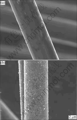
Fig.1 SEM images of bare carbon fiber (a) and carbon fiber coated with PB (b)
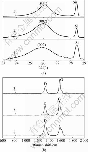
Fig.2 XRD patterns (a) and Raman spectra (b) of PAN-based carbon fibers heat-treated at different temperatures: 1��2 000��; 2��2 400 ��; 3��2 800 ��
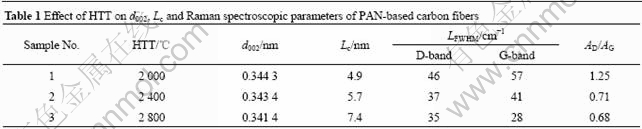
Moreover, the smaller values of AD/AG and LFWHM mean a higher extent of graphitization [11]. It can be seen from Table 1 that AD/AG and LFWHM all decrease with increasing HTT. From Fig.2 and Table 1, it is noted that the extent of graphitization increases with the increase of HTT. However, PAN-based carbon fibers are hard- graphitizable even heat-treated at above 2 000 ��. When the HTT is raised to 2 800 ��, the value of Lc is just 7.4 nm and the value of d002 reaches 0.341 4 nm, for instance.
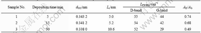
The XRD patterns and Raman spectra of PAN-based carbon fibers coated with PB through heat treatment at different temperatures are shown in Fig.3. The HTTs of PB-coated carbon fibers ranging from 1 500 to 1 900 �� are lowered more than 500 �� compared with those of bare carbon fibers. It can be seen that in addition to the shift of the (002) peak to the right in Fig.3(a), the peak also becomes sharper and more symmetric as the HTT increases. Curve 1 in Fig.3(a) has a broad hump, which means that the extent of graphitization of PB-coated carbon fibers heat-treated at 1 500 �� is still low. When the HTT is raised to 1 700 ��, the (002) peak shifts to the right but is dispersive, indicating that the microstructure of PB-coated carbon fibers is heterogeneous and only a part of carbon turns to graphite. However, curve 3 in Fig.3(a) has a symmetric (002) peak. Apparently, the PB-coated carbon fibers have a high extent of graphitization when heat-treated at 1 900 ��. Raman spectroscopic parameters (LFWHM and AD/AG) were also obtained after curve fitting the experimental spectra shown in Fig.3(b). Table 2 that summarizes the values of d002, Lc and Raman spectroscopic parameters, shows that Lc increases with the increase of the HTT, but d002 decreases with the increase of HTT. When the HTT is raised to 1 900 ��, Lc is 21.2 nm and d002 reaches 0.336 8 nm which is very close to that of hexagonal graphite (0.335 4 nm). From Table 2, it can be also found that LFWHM and AD/AG in Raman spectra decrease with the increase of HTT. It is also noted that the G-band FWHM (LFWHM, G) for PB-coated carbon fibers heat-treated at 1 900 �� is 23 cm-1, which is close to that of highly oriented graphite (21 cm-1) [8]. Although the HTTs of PB-coated carbon fibers are lower than those of bare carbon fibers, PB-coated carbon fibers have higher extent of graphitization than bare carbon fibers after heat treatment, which shows that PB coating has catalytic effect on the graphitization of PAN-based carbon fibers. The research results illustrate that the thickness of PB coating (PB content) increases linearly with the increase of deposition time. The influence of PB deposition time (5, 15, and 30 min) on the extent of graphitization was discussed. Table 3 lists the changes of XRD data (d002 and Lc) and Raman spectroscopic parameters of carbon fibers with different PB deposition time at the HTT of 1 700 ��. It is clear that the catalytic graphitization effect of PAN-based carbon fibers increases with the increase of PB deposition time, i.e., PB content. Therefore, the extent of graphitization is related to not only HTT but also PB content.
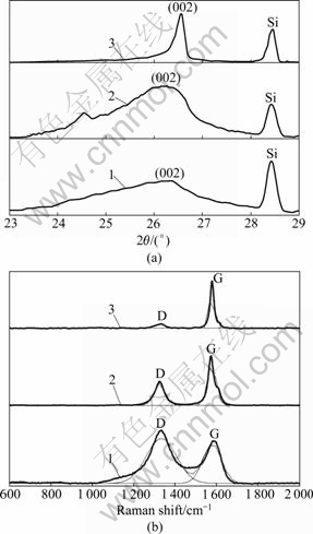
Fig.3 XRD patterns (a) and Raman spectra (b) of PAN-based carbon fibers coated with PB (depositing for 15 min) and heat- treated at different temperatures: 1��1 500 ��; 2��1 700 ��; 3��1 900 ��
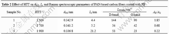
Table 3 Effect of PB deposition time on d002, Lc and Raman spectroscopic parameters at HTT of 1 700 ��
The HRTEM image of the PB-coated carbon fiber after heat treatment shows that after 1 900 �� heat treatment, highly ordered layers stack with an interlayer space (d002) of 0.337 0 nm (Fig.4). This indicates that graphitized crystallization is achieved in the carbon fibers.
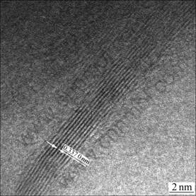
Fig.4 HRTEM image of PAN-based carbon fiber coated with PB after heat-treated at 1 900 �� for 2 h
The catalytic graphitization effect of PB on PAN-based carbon fibers is attributed to the fact that PB contains Fe element in both Fe2+ and Fe3+ valence states. In general, the catalyst Fe element follows the well-known dissolution-precipitation mechanism [4, 12]. Fig.5 shows the cross-section images of the original carbon fiber and the PB-coated carbon fiber heat-treated at 1 900 ��. In comparison with Fig.5(a), the PB-coated fiber��s cross-section changes from a flat surface to a rough surface after catalytic graphitization. It is also observed from Fig.5(b) that the outside of the carbon fiber is rougher than the center. This indicates that the process of catalytic graphitization proceeds from the outer surface to the center of the carbon fiber. Moreover, there is no defect on the PB-coated carbon fiber after heat treatment. As PB can be uniformly deposited on the surface of carbon fibers, the SEM observation in Fig.5(b) suggests that the process of catalytic graphitization proceeds from the outer surface where carbon contacts with Fe in the PB coating, and Fe element dissolves carbon and precipitates from the outer surface. Hence, catalytic graphitization using PB as catalyst has slight impact on the mechanical property of carbon fibers.

Fig.5 SEM images of cross-section configuration of original carbon fiber (a) and carbon fiber coated with PB after heat- treated at 1 900 �� (b)
4 Conclusions
(1) PAN-based carbon fibers are non-graphitizable even heat-treated at above 2 000 ��.
(2) PB has significantly catalytic effect on graphitization of PAN-based carbon fibers. To obtain the same extent of graphitization, PB can make HTT decrease more than 500 �� compared with that of the bare carbon fibers.
(3) The HTT and the thickness of PB coating (PB content) play a key role in the catalytic effect on graphitization of PAN-based carbon fibers. In a certain range, the extent of graphitization of PAN-based carbon fibers can be controlled by adjusting the HTT and PB content.
References
[1] YI Shou-jun, FAN Zhen, WU Chao, CHEN Jin-hua. Catalytic graphitization of furan resin carbon by yttrium [J]. Carbon, 2008, 46(2): 378-380.
[2] XU Bing-she, ZHANG Chun-yi, YANG Yong-zhen, LIU Xu-guang, LUO Qiu-ping. FeCl3-catalyzed growth of vapor-grown carbon fibers from deoiled asphalt [J]. New Carbon Mater, 2007, 22(3): 193-198.
[3] FAN Na, MA Xi-cheng, LIU Xi-zheng, XU Li-qiang, QIAN Yi-tai. The formation of a layer of Fe3O4 nanoplates between two carbon films [J]. Carbon, 2007, 45(9): 1839-1846.
[4] ANTON R. In situ TEM investigations of reactions of Ni, Fe and Fe-Ni alloy particles and their oxides with amorphous carbon [J]. Carbon, 2009, 47(3): 856-865.
[5] DHAKATE S R, MATHUR R B, BAHL O P. Catalytic effect of iron oxide on carbon/carbon composites during graphitization [J]. Carbon, 1997, 35(12): 1753-1756.
[6] DEREK F L, CHENG I F. Analysis of hydrogen peroxide and organic hydroperoxide via the electrocatalytic fenton reaction [J]. Microchemical Journal, 2009, 91(1): 78-81.
[7] QIU Jian-ding, DENG Min-qiang, LIANG Ru-ping, XIONG Meng. Ferrocene-modified multiwalled carbon nanotubes as building block for construction of reagentless enzyme-based biosensors [J]. Sensors and Actuators B, 2008, 135(1): 181-187.
[8] ZHAO Chang-zhi, WAN Li, JIANG Li, WANG Qin, JIAO Kui. Highly sensitive and selective cholesterol biosensor based on direct electron transfer of hemoglobin [J]. Analytical Biochemistry, 2008, 383(1): 25-30.
[9] GAO Peng-zhao, WU Ming-jian, LI Bai-jun, LIU Yan-li. Structure characterization and oxidation mechanism study of porous biomorphic carbon template derived from basswood [J]. Mater Res Bull, 2009, 44(3): 644-648.
[10] GERALD A Z, BERND S, NOTBURGA G, HERWIG P, OSKAR P. A reconsideration of the relationship between the crystallite size La of carbons determined by X-ray diffraction and Raman spectroscopy [J]. Carbon, 2006, 44(15): 3239-3246.
[11] TZENG S S. Catalytic graphitization of electroless Ni-P coated PAN-based carbon fibers [J]. Carbon, 2006, 44(10): 1986-1993.
[12] IGNACIO M G, JOSE V, JUAN A C, JOSE L G. Differences between carbon nanofibers produced using Fe and Ni catalysts in a floating catalyst reactor [J]. Carbon, 2006, 44(8): 1572-1580.
Foundation item: Project(2006CB600903) supported by the National Basic Research Program of China
Received date: 2009-10-10; Accepted date: 2010-03-16
Corresponding author: KUANG Ya-fei, Professor; Tel: +86-731-88821874; Fax: +86-731-88713642; E-mail: yafeik@163.com
(Edited by CHEN Wei-ping)
