
Trans. Nonferrous Met. Soc. China 26(2016) 2067-2078
Influence of flash trap profiles on joint properties of friction welded CP-Ti tube to 304L stainless steel tube plate using external tool
C. MAXWELL REJIL1,2, C. SHARAN2, S. MUTHUKUMARAN2, M. VASUDEVAN3
1. Department of Mechanical Engineering, CMR Institute of Technology, Bangalore 560037, India;
2. Department of Metallurgical and Materials Engineering, National Institute of Technology, Tiruchirappalli 620015, India;
3. Advanced Welding Processes and Modeling Section, Materials Technology Division, Indira Gandhi Centre for Atomic Research, Kalpakkam 603102, India
Received 17 July 2015; accepted 2 January 2016
Abstract:
Titanium tube and stainless steel tube plate were welded by an innovative friction welding of tube to tube plate using an external tool (FWTPET). Copper was used as an interlayer for joining the dissimilar materials and also to minimize the effect of intermetallics formed at the joint interface. The process parameters that govern FWTPET process are plunge rate, rotational speed, plunge depth, axial load and flash trap profile. Among them, the flash trap profile of the tube has a significant influence on the joint integrity. Various flash trap profiles like vertical slots, holes, zig-zag holes, and petals were made on the titanium tube welded to the stainless steel tube plate. Macroscopic and microscopic studies reveal defect-free joints. The presence of copper interlayer and intermetallics was evident from X-ray diffraction (XRD), scanning electron microscopy (SEM) and energy dispersive spectroscopy (EDS) studies. The microhardness survey was presented across and along the interface. A novel test procedure called ��plunge shear test�� was developed to evaluate the joint properties of the welded joints. The highest shear fracture load of 31.58 kN was observed on the sample having petals as flash trap profile. The sheared surfaces were further characterized using SEM for fractography.
Key words:
304L stainless steel tube plate; CP-Ti tube; friction welding; joint properties; flash trap; external tool;
1 Introduction
Commercially pure titanium (CP-Ti) is the workhorse for industrial applications due to its excellent ductility, formability and high specific strength. The presence of very low interstitials in CP-Ti will enhance erosion and corrosion resistance [1]. Stainless steel (SS-304L) with low carbon content and enhanced mole ratio of Cr to Ni is extensively used in chemical, textile and processing industries. It offers very high strength and excellent corrosion resistance. The increase of manufacturing cost and the demand for superior corrosion resistant materials result in the need for bimetallic systems. One example is the use of SS-Ti bimetallic joints in the spent fuel reprocessing unit of nuclear power plants. In these plants, boiling nitric acid carries the spent nuclear fuel from a titanium dissolver vessel through stainless steel pipes to other processing units [2-4]. Since the SS-Ti transition joint operates in an acidic environment, a leak-proof joint is very essential.
The welding of the titanium-stainless steel dissimilar combination leads to the formation of intermetallics irrespective of the welding process used. The formation of brittle hard intermetallic phases is detrimental to the joint properties. The concept of adopting an interlayer between the two metals is introduced to reduce the detrimental effects of intermetallics at the interface. KUNDU et al [5-7] successfully joined CP-Ti with stainless steel using copper as an interlayer by diffusion bonding. Copper interlayer also improves the bond strength by increasing the flowability at the contact area [8]. Nickel, silver, gold and platinum can also be used as interlayers, but the costs of these metals hinder their usage.
The welding of stainless steel tube to titanium tube plate or vice-versa by conventional fusion or solid-state welding processes for stringent applications is extremely difficult. In fusion welding of dissimilar metals, enormous strain is induced at the interface which leads to distortion. The differences in thermal expansion and thermal conductivity of the base metals are the prime reasons for distortion to occur [9]. SHANMUGARAJAN et al [10] successfully welded Ti-SS combination by laser welding. They reported that autogenous fusion welding of this dissimilar combination is not feasible due to high cooling rate that causes weld embrittlement. They concluded that the use of tantalum strip as interlayer improved the joint strength and weldability. WANG et al [11,12] successfully welded Ti-15-3 and 304 stainless steel by electron beam welding using copper as a transition layer. They also reported that the welding of titanium and stainless steel is possible by varying interlayers such as vanadium, silver and nickel. Thus, in Refs. [13-15] on fusion welding, it is evident that joints can be obtained using a transition layer which gives better joint strength. Among solid-state welding processes, the most probable ones for welding tube to tube plate configuration are pressure welding, friction welding, explosive welding, diffusion bonding, ultrasonic welding and laser forming. Though explosive welding can be used for joining tube to tube plate [16], the usage of explosives always creates safety issues in industries. Diffusion bonding is an excellent alternative for joining Ti-SS, as reported in Refs. [17-21]. The constraints faced in diffusion bonding of join tube to tube plate are the joint configuration and its anomalies.
In order to overcome the issues faced in joining tube to tube plate configuration, a novel solid state joining process called friction welding of tube to tube plate using an external tool (FWTPET) was developed. Conventional radial friction welding process [22] can be used to join tubes together. But when joining a tube to a tube plate, configuration conventional friction welding fails in its purpose. FWTPET is an eco-friendly solid-state welding process that has been successfully used to weld similar and dissimilar metals with improved joint properties. This process was invented and patented by one of the present authors [23]. The process parameters that generally influence this process are tool rotational speed, plunge rate, plunge depth, axial load, and flash trap profile. The FWTPET machine setup consists of an external tool that acts as heat generating component for joining. This tool consists of a shoulder and a pin. The external tool is plunged with a defined plunge rate rotating at a constant speed. During plunging, frictional heat is generated as the shoulder touches the tube and tube plate. This frictional heat induces plastic flow in the material and plunges downward. The plasticized material is guided by the tool pin to fill the flash trap. FWTPET process can be done by two methods, namely clearance method and interference method. FWTPET process by clearance method was used to join aluminum tube to aluminum tube plate to get high quality defect-free joints [24]. Previously, friction welding of copper tube to aluminum tube plate was successfully done by interference method [25]. The maximum joint strength of 148 MPa and the presence of Al-Cu intermetallics were also reported.
In this study, an effort was made to improve the joint integrity of friction welded titanium tube to stainless steel tube plate by clearance method. The flash trap profiles influenced more on the material flow during plunge stage of FWTPET process. Hence, an elaborate work was done by varying the flash trap profiles such as vertical slots (VS), zig-zag holes (ZZ), holes and petals representation. From this study, the flash trap profile that is preferable for improving the joint integrity can be determined.
2 Experimental
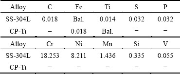
The materials used are 304L austenitic stainless steel and commercially pure titanium (Grade-2). The chemical compositions and optical photomicrographs of the base materials are presented in Table 1 and Fig. 1, respectively. In Fig. 1(a), the microstructure of austenitic stainless steel shows the typical characteristic formation of annealing twins. The microstructure of CP-Ti (Fig. 1(b)) exhibits grains with clear grain boundaries that represents the alpha phase in the matrix. Copper foil with 99.95% purity and 100 ��m in thickness was used as the interlayer for joining the dissimilar metals.
Table 1 Chemical compositions of base metals (mass fraction, %)
The as-received rolled stainless steel plates were sheared into 50 mm �� 50 mm pieces by a shear cutting machine and a hole of 19 mm in diameter was drilled on the center of the plate. CP-Ti tube with height of 30 mm and outer and inner diameters of 19 and 14 mm, respectively, was used.
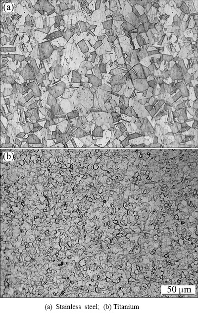
Fig. 1 Microstructures of base materials
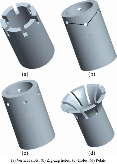
Fig. 2 Three-dimensional models of different flash trap profiles
As mentioned above, the flash trap profiles such as petals, holes, vertical slots and zig-zag holes (Fig. 2) were made on the circumference of the tube as explained below.
Vertical slots profile (Fig. 2(a)): In vertical slots, 2 mm in width and 7 mm in depth slots were machined on the circumference of the tube from top surface. The distance between the slots was maintained by separating it at equal angles (~60��).
Zig-zag holes profile (Fig. 2(b)): In zig-zag profile, the holes with 2 mm in diameter were drilled at equal angles (~60��). The zig-zag pattern was formed on the circumference of the tube, by drilling alternate even numbered holes at a depth of 3.5 mm and odd numbered holes at a depth of 4 mm.
Holes profile (Fig. 2(c)): In holes profile, the holes with 2 mm in diameter were drilled on the circumference of the tube at a depth of 3.5 mm from the top surface. The holes were separated from each other at equal angles (~60��).
Petals profile (Fig. 2(d)): The petals profile was made on circumference of the tube, by machining suitable slots with 1.5 mm in width and 10 mm in depth. These slots were separated by equal angles (~60��) between them. The petal shape profile was then formed on the tube using a tapered tool.
The backing block used to hold the work-piece was made of EN-8 steel. It was designed that the work-piece was totally constrained during welding. Sand paper and acetone were used to clean the surface of tube plate, tube and copper foil. After cleaning, the tube was wrapped with copper interlayer and interference fitted to the tube plate. FWTPET process was carried out in a 4-axis friction stir welding machine manufactured by BiSS-ITW, Bangalore. The assembled workpiece with the tube, tube plate and interlayer was fixed to the backing block. The schematic of FWTPET process and welding setup is shown in Fig. 3. A projection of 2 mm was provided to the tube. The backing block was then fixed to the machine table. Customized software was used to weld FWTPET samples in the existing friction stir welding (FSW) machine. The process parameters were optimized after a series of trial welds. The following process parameters, rotational speed of 900 r/min, plunge rate of 1.5 mm/min and plunge depth of 4 mm, were kept constant for the entire study. The axial load during welding was found to vary continuously along the entire weld depth, reaching the maximum load of 28 kN. The external tool used for welding was made of tungsten alloy, which acted as a non-deformable rigid tool during the entire welding process.
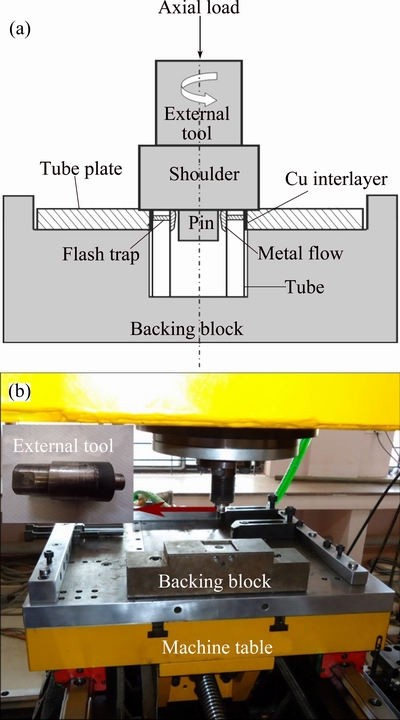
Fig. 3 Schematic of FWTPET (a) and welding setup (b)
The macrograph of the welded sample was captured using a stereo microscope. The dissimilar materials were etched individually and the optical micrographs obtained were stitched together for clarity. The titanium side was etched with an aqueous solution containing 3 mL HNO3, 3 mL HCl, 8 mL HF and 37 mL distilled water. A solution of 5 mL HNO3, 10 mL glycerol and 15 mL HCl was used for etching the austenitic stainless steel side. Electron microscopic studies were carried out on a field emission scanning electron microscope (FESEM), SIGMA HV model manufactured by Carl Zeiss, Germany. The images were taken in back scattered diffraction mode. The energy dispersive spectroscopy (EDS) analysis was performed on the above mentioned machine with a BRUKER QUANTAX 200-Z10 EDS detector attachment. The X-ray diffraction (XRD) analysis (RIGAKU) was carried out on the welded samples to identify the phases formed by welding. The operating voltage was 30 kV from the copper target with the following parameters: scan rate of 2 (��)/min, step width of 0.05�� and scan range of 30�� to 90��. The microhardness of the welded sample was measured across and along the interface, using 5 N load and 15 s dwell time. The distance between two indentations was 0.25 mm.
The schematic of plunge shear test (PST) and experimental setup is shown in Fig. 4. The PST procedure is similar to ram tensile test [26]. During ram tensile test, load is applied perpendicular to the weld zone, whereas in the PST, the load is applied parallel to the weld zone. The test is designed such that the entire load is taken by the weld joint. Also, during PST, the cross head speed of the universal testing machine (UTM) was maintained constant. For welding, a specially designed PST tube with 30 mm in height, where top half was hollow and the remaining half was solid, was used. PST was carried out on a universal testing machine with a cross head speed of 3 mm/min. A plunger was used to apply load on the top half hollow end of the PST tube. The fractured samples were examined on both titanium and stainless steel sides for surface morphology studies. Fractography was done on an S-3000H type scanning electron microscope (SEM) manufactured by HITACHI.
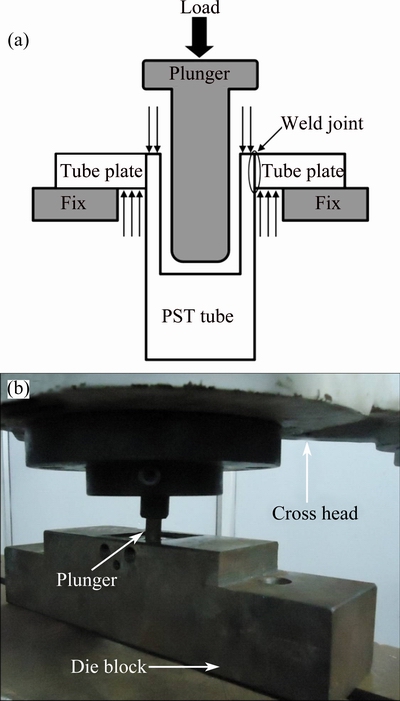
Fig. 4 Schematic of PST (a) and experimental setup (b)
3 Results and discussion
Dissimilar joining of titanium tube to stainless steel tube plate was carried out using copper as an interlayer with four different flash trap tube profiles. The FWTPET process parameters such as plunge depth, rotational speed and plunge rate were optimized after a series of trial experiments. Figure 5 shows the appearance of the welded specimens after FWTPET process. On visual examination, it is observed that the welded specimens are free from surface defects such as cracks, inclusions and improper fill. The concentric ring pattern shown in Fig. 5(a) is the characteristic appearance of FWTPET welds. This pattern is caused due to the rubbing action of the tool shoulder on the plate surface. Figure 5(c) shows the cut section view of the welded sample.
3.1 Macrostructure of welded specimens
The macrostructures of the welded samples show a magnified view of the joint interface, as shown in Fig. 6. From the macrographs, it is clear that the joint interfaces are free from defects. The macrostructures bring out the flow patterns of material when the flash trap profiles vary. The material flow is also influenced by plunge rate, rotational speed, continuously varying axial load and plunge depth. The macrograph of the vertical slots profile shown in Fig. 6(a) presents a cap-like formation.
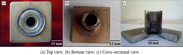
Fig. 5 Welded specimens
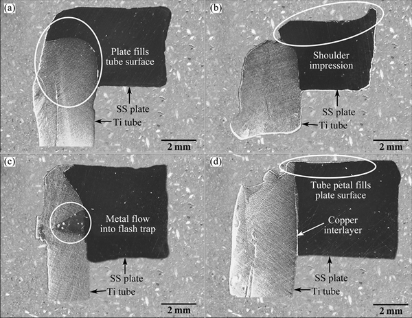
Fig. 6 Macrographs of vertical slots (a), zig-zag holes (b), holes (c) and petals (d)
During plunging, frictional heat is developed by the combined action of rotating tool shoulder and continuously varying axial load. The severity of frictional heat and axial load initially plasticizes the titanium tube. The less dense titanium tube deforms and flows continuously by the defined plunge rate. When the shoulder touches the plate surface, the denser stainless steel plate pushes titanium tube further downwards. This attributes to the downward plasticized movement of plate material and it covers the top surface of the tube. Hence, it totally influences the material to flow down giving a peculiar cap-like formation.
The macrostructure of zig-zag holes is shown in Fig. 6(b). From the macrograph, it is clear that the tool shoulder plunges into the plate surface leaving tool shoulder impression. Also, incomplete filling of zig-zag holes is also observed. This incomplete filling is due to the constant plunge depth being maintained for the entire welding process. Due to the defined plunge depth, complete filling of even holes and partial filling of odd holes are observed. Figure 6(c) shows the macrostructure of circumferential holes profile. In this macrograph, the clear evidence of tube plate material filling the flash trap is seen. This is due to high axial force that pushes and drives the tube plate material to fill the circumferential holes at exact depth from top surface.
In Fig. 6(d), it is evident that the petals profile completely covers the plate surface. The presence of copper interlayer is clearly visible. The petals profile indicates that those joint interfaces are free from defects and the copper foil keeps dissimilar materials intact. Thus, from the macrostructures, defect free weld joints are observed for dissimilar materials by varying the flash trap profiles.
3.2 Microstructural analysis
The optical micrographs of the welded samples are shown in Figs. 7(a1, b1, b1, d1). It is evident from the micrographs that the joint interfaces are free from defects. For a defect-free joint, proper metal flow towards the flash trap is essential. During welding, the rotating external tool is lowered with a defined plunge rate. Due to the projection provided, the rotating external tool will first touch the titanium tube and produce frictional heat. This frictional heat along with the axial and rotational forces plasticize the tube material, forcing the metal to flow towards the central axis. When the heated tool touches the stainless steel plate, the surface of the plate is easily plasticized due to the combined action of tool heat, rotation speed and axial force. The constraints provided by the backing block will also force the plasticized plate material to flow towards the central axis through the flash trap. At the central axis, the tool pin acts as an anvil, preventing the flow of both the plasticized materials. Due to the opposing forces, the plasticized materials are forced to fill the flash trap forming a defect-free joint.
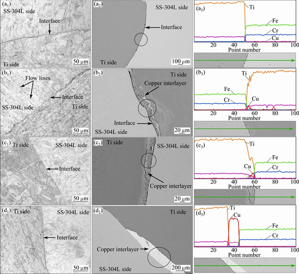
Fig. 7 Optical micrographs (a1, b1, c1, d1), SEM images (a2, b2, c2, d2) and EDS plots (a3, b3, c3, d3) of vertical slots (a1-a3), zig-zag holes (b1-b3), holes (c1-c3) and petals (d1-d3)
Figures 7(a1)-(a3) show the optical micrograph, SEM image and EDS plot of vertical slots profile, respectively. From the micrographs, it is clear that the interface is intact without any defects. The presence of copper is not evident in the SEM image. The EDS line scan taken along the interface shows very low mole fraction of copper. The titanium side exhibits phase change because of very high temperature and the diffusion of copper. The copper diffusion promotes beta phase transformation along with high temperature during joining process. The micrographs of zig-zag profile are shown in Figs. 7(b1) and (b2). The optical micrograph shows clear interface with no trace of copper interlayer. The SEM image of zig-zag profile shows the presence of copper, forming thin layer of intermetallics. The EDS line scan for zig-zag profile is shown in Fig. 7(b3). The dissolution of copper into the matrix of titanium is evident from the copper peak emerged along with titanium peaks at the joint interface. Copper does not form any solid solution with stainless steel but it is soluble in titanium, producing a range of intermetallics.
The SEM image of holes profile exhibits thin intermetallic layer of ~20 ��m, as shown in Fig. 7(c2). The presence of copper as intermetallic is more easily understood from the EDS peaks shown in Fig. 7(c3). The joint interface shows peaks of copper and titanium, which clearly indicates the formation of Ti-Cu intermetallics. Figures 7(d1) and (d2) show the micrographs of petals profile. In Fig. 7(d2), the electron micrograph clearly shows the copper interlayer that remains partially dissolved in the titanium matrix. The presence of undissolved copper is due to the presence of titanium petals which takes away most of the generated frictional heat. The corresponding EDS peaks of the petals are shown in Fig. 7(d3). The presence of partially mixed copper with titanium is evident from high mass fraction of copper peaks at the joint interface. The presence of copper promotes the formation of Ti-Cu intermetallics. In the petals profile, 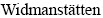 bands are observed in titanium in the top region. Other regions show fine and coarse grain microstructures, as shown in Fig. 7(d1).
The stainless steel side does not show microstructural change or phase transformation. This is evident from identical annealing twins shown in Figs. 7(a1), (b1), (c1) and (d1), which are characteristics of austenite stainless steel. The titanium side shows band formation close to the joint interface in the vertical slots, zig-zag and holes profiles, as shown in Figs. 7(a1), (b1) and (c1). The bands indicate that the titanium side has been subjected to temperatures higher than 882 ��C.
Figure 8 shows the micrographs of petals profile. Due to the decrease of temperature along the interface, the copper interlayer is partially dissolved, as shown in Fig. 8(b). The regions where copper is completely dissolved are observed, giving rise to the formation of bands. The rest of the region shows fine grain microstructure. The titanium tube experiences phase transformation from �� phase (HCP) to �� phase (BCC). This transition from �� to �� phase is evident from the bands shown in Fig. 8(c). The microstructure shows bands, which contains �� phase with needles of �� phase. The band formation can also be attributed to the presence of copper interlayer. Copper acts as a �� stabilizer, which promotes the formation of bands. Due to more open space in the BCC structure of titanium (�� phase), it can readily accept copper in its lattice, thereby forming Ti-Cu intermetallics [27].
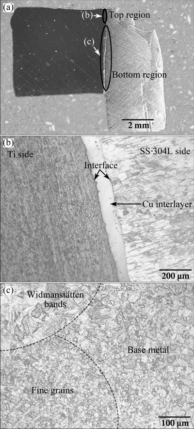
Fig. 8 Micrographs of petals profile
3.3 XRD analysis
The XRD patterns were analyzed for varying flash trap profiles and base materials, as shown in Fig. 9. The formation of intermetallics in the interface zone and adjacent matrix was confirmed by the XRD patterns of varying flash trap profiles. The XRD analysis indicates the presence of ��-Ti, TiFe2, Cu3Ti2, Cr2Ti and CuTi2. The formation of TiFe2 and Cr2Ti indicates the complete dissolution of copper interlayer, which leads to the diffusion of stainless steel and titanium. In the XRD analysis, there is no evident formation of Fe-Cu binary systems. This is due to the closed packed crystal structure of austenitic phase that hinders the diffusion of copper into the matrix. The presence of TiFe2 and Cu3Ti2 intermetallics along with base metal is evident for petals profile. The EDS plot also confirms the presence of intermetallics, as mentioned in Fig. 7(d3). The XRD peaks for holes profile show the presence of Cr2Ti and CuTi2. The formation of Cr2Ti proves that titanium diffuses through copper interlayer. The XRD peaks of vertical slots and holes profiles indicate numerous peaks of Ti-Fe binary system. This is due to complete dissolution of copper interlayer. The same result can be confirmed from microstructural studies as explained in Section 3.2. The XRD peaks confirm ��-Ti formation in holes, zig-zag holes and vertical slots flash trap profiles. This formation of ��-Ti is due to phase transformation that takes place during welding.
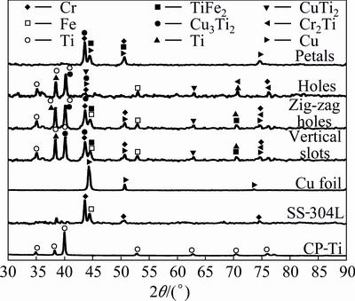
Fig. 9 XRD patterns of varying flash trap profiles
3.4 Microhardness
The microhardness survey was carried out across the interface at three different locations for repeatability and the average values are shown in Fig. 10(a). Across the interface, the peak hardness of HV 288 is observed for vertical slots, whereas petal profile has the lowest hardness of HV 182. The variation in peak hardness in vertical slots and petals is due to the formation of hard and soft intermetallics at the interface. The hard intermetallics such as TiFe2 and Cr2Ti are formed by direct diffusion of titanium and stainless steel. The soft intermetallics such as Cu3Ti2 and CuTi2 are formed by titanium diffusion in the copper matrix. The formation of hard and soft intermetallics was also confirmed from the studies made by other researchers [28,29]. The titanium tube experiences an increase of hardness after welding compared with as-received material (as-received titanium sample is ~HV 156). The increase of hardness is due to the phase transformation occurring during welding. The stainless steel side does not undergo phase transformation and no significant variation in microhardness is observed.
The microhardness along the weld interface is shown in Fig. 10(b). The vertical slots show the highest hardness of HV 364 in the top region. This high hardness is due to high frictional heat generated on the plate surface, which favors the formation of TiFe2 intermetallics. The peak hardness values are observed in this region. A very low hardness of HV 139 is observed in petal profile due to the presence of soft Cu3Ti2 phase in the bottom region.
Fig. 10 Microhardness across interface (a) and along interface (b)
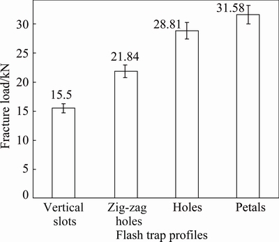
Fig. 11 Shear fracture load of different flash trap profiles
3.5 Plunge shear test (PST)
In order to determine the joint integrity, a novel test procedure ��plunge shear test�� was developed. For repeatability, three samples were welded for each flash trap profile keeping other process parameters constant. The shear fracture loads of varying flash trap profiles are shown in Fig. 11. The petals profile shows the highest fracture load of 31.58 kN followed by holes and zig-zag holes profiles. The vertical slots profile records the lowest shear fracture load of 15.5 kN.
The wide difference in fracture load can be explained by the macrographs shown in Fig. 6. In the vertical slots profile, the cap formation of plate material over the tube is observed in Fig. 6(a). When the profile was subjected to PST, the joint sheared without offering much resistance. In Fig. 6(b), the zig-zag holes profile shows the impression of the tool shoulder on the plate surface and improper filling of the holes. The zig-zag holes welded samples loaded in the PST offer better
resistance compared with the vertical slots specimen. The holes profile shows complete filling of holes, which fractures at a load of 28.81 kN. This high fracture load is due to the formation of interlocking mechanism between the plate and tube. The petals profile withstands higher fracture load, due to the gripping of titanium tube petals over the surface of stainless steel plate. The presence of Cu3Ti2 and CuTi2 soft intermetallics at the interface is also a contributing factor for its high fracture load.
During the plunge shear test, the joint interface fractures by plunge shear load. On visual appearance, it is observed that copper interlayer adheres more on the titanium tube than on the stainless steel tube plate. The above argument was elaborated with Ti-Cu binary system formation in Section 3.3. The fracture seems to be initiated along stainless steel/copper interface. To provide more evidence on fracture studies, fractography was carried out on both titanium and stainless steel side.
The surface morphologies obtained using scanning electron microscopy are presented in Fig. 12. The following observations are made from the fractographs.
Vertical slots: The stainless steel side shows no visible fracture patterns (Fig. 12(a)). The titanium side reveals flat fracture (Fig. 12(b)).
Zig-zag holes: Stainless steel and titanium reveal partial river flow patterns (Figs. 12(c) and (d)).
Holes: The presence of cleavage facets (Fig. 12(e)) is observed on the stainless steel side. Titanium shows intermittent river flow pattern and cleavage facets (Fig. 12(f)).
Petals: Stainless steel shows continuous river flow pattern (Fig. 12(g)). Titanium shows deep cleavage facets (Fig. 12(h)) on the fractograph.
The appearance of river flow pattern occurs on the stainless steel side owe to directionality in crack growth. The crack growth propagates along the grain boundaries showing a typical formation of twist deformation component. The direction of crack growth is parallel to the direction of crack coalescence. The presence of cleavage facets on the titanium side can be attributed to the diffusion of titanium during joining process.
The distinctive river flow lines that occur along the cleavage further signify brittle mode on fracture during complete shear. The occurrence of flat fracture, river flow pattern and cleavage facets is influenced by the crystal structure formation at the interface [30]. The shear mode of failure can also be attributed to microstructure appearance, plunge rate during shear, plunge depth and frictional heat developed during tool rotation.
4 Conclusions
1) The optical micrographs show defect-free joints in all flash trap profiles. Due to frictional heat on the surface of tube and tube plate during welding, the phase transformation is only observed on the titanium tube. The phase transformation is confirmed through micro- structural and XRD analyses.
2) The scanning electron studies carried out on the joint interface reveal the presence of copper interlayer and intermetallic formation at the interface.
3) The EDS studies confirm the presence of copper interlayer and potential intermetallic formation at joint interface.
4) Microhardness survey was done across and along the interface of the welded sample. The peak hardness of HV 364 at the interface is observed in the vertical slots profile followed by zig-zag holes and holes profiles. The petals profile shows low hardness values of HV 182 and HV 139 across and along the interface, respectively. This is attributed to the regions where copper interlayer is partially dissolved, thereby forming soft Ti-Cu intermetallics.
5) The XRD patterns show various phases and intermetallic compounds formed during welding. The region where high frictional heat is experienced favors the formation of TiFe2 and Cr2Ti intermetallics. The regions where the heat flow is the minimum contribute to the formation of Cu3Ti2 and CuTi2 intermetallics.
6) A new test procedure called ��plunge shear test�� was developed to determine the fracture shear load of the welded joints. The petals profile has the highest fracture load of 31.58 kN and the vertical slots profile has the lowest fracture load of 15.5 kN. The effect of flash trap on joint integrity is attributed to the material flow pattern and intermetallic formation.
7) Due to flash trap profiles, the macrographic observation of the welded region provides necessary information on metal flow. The SEM images of the fracture surface of titanium and stainless steel reveal the change in fracture pattern in different flash trap profiles. Different fracture morphologies such as flat fracture, cleavage facets and river flow pattern are observed. This type of fracture appearance is an indication that the weld joints fracture in shear mode during plunge shear.
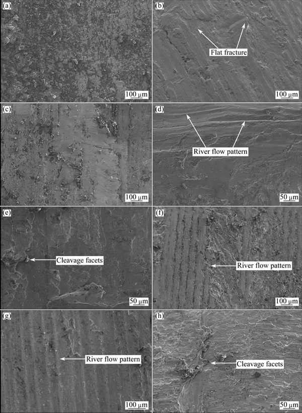
Fig. 12 Fractographs of vertical slots (a, b), zig-zag holes (c, d), holes (e, f), petals (g, h) of SS 304L-side (a, c, e, g) and CP-Ti side (b, d, f, h)
Acknowledgements
The authors acknowledge the financial support provided by UGC-DAE-CSR (CSR-KN/CRS-04/2012- 13/738) through fellowship. The authors are grateful to the Institution and Department of Metallurgical and Materials Engineering, for providing necessary facilities to carry out the work. The authors are thankful to Dr. R. SATHISKUMAR, Department of Mechanical Engineering, CIT, Coimbatore, for his support. The authors also acknowledge Mr. P. RAJESH KANNAN, Mr. P. BHAGAT SINGH, and Mr. K. VINOADH KUMAR, Research Scholars, Department of Metallurgical and Materials Engineering, to execute the work.
References
[1] RODNEY B, GERHARD W, COLLINGS E W. Materials properties handbook: Titanium alloys [M]. Materials Park, OH: ASM International, 1994.
[2] KUNDU S, CHATTERJEE S. Characterization of diffusion bonded joint between titanium and 304 stainless steel using a Ni interlayer [J]. Materials Characterization, 2008, 59: 631-637.
[3] GHOSH M, CHATTERJEE S. Characterization of transition joints of commercially pure titanium to 304 stainless steel [J]. Materials Characterization, 2002, 48: 393-399.
[4] KAMACHI M U, ANANDA R B M, SHANMUGAM K, NATARAJAN R, RAJ B. Corrosion and microstructural aspects of dissimilar joints of titanium and type 304L stainless steel [J], Journal of Nuclear Materials, 2003, 321: 40-48.
[5] KUNDU S, GHOSH M, LAIK A, BHANUMURTHY K, KALE G, CHATTERJEE S. Diffusion bonding of commercially pure titanium to 304 stainless steel using copper interlayer [J]. Materials Science and Engineering A, 2005, 407: 154-160.
[6] KUNDU S, CHATTERJEE S. Microstructure and mechanical properties of diffusion bonded joints between titanium and stainless steel with copper interlayer [J]. Science and Technology of Welding and Joining, 2007, 12: 572-578.
[7] KUNDU S, CHATTERJEE S, OLSON D, MISHRA B. Interface microstructure and strength properties of the diffusion-bonded joints of titanium/Cu interlayer/stainless steel [J]. Metallurgical and Materials Transactions A, 2008, 39: 2106-2114.
[8] ELREFAEY A, TILLMANN W. Effect of brazing parameters on microstructure and mechanical properties of titanium joints [J]. Journal of Materials Processing Technology, 2009, 209: 4842-4849.
[9] ELREFAEY A, TILLMANN W. Brazing of titanium to steel with different filler metals: Analysis and comparison [J]. Journal of Materials Science, 2010, 45: 4332-4338.
[10] SHANMUGARAJAN B, PADMANABHAM G. Fusion welding studies using laser on Ti-SS dissimilar combination [J]. Optics and Lasers in Engineering, 2012, 50: 1621-1627.
[11] WANG T, ZHANG B, WANG H, FENG J. Microstructures and mechanical properties of electron beam-welded titanium-steel joints with vanadium, nickel, copper and silver filler metals [J]. Journal of Materials Engineering and Performance, 2014, 23: 1498-1504.
[12] WANG T, ZHANG B, FENG J. Influences of different filler metals on electron beam welding of titanium alloy to stainless steel [J]. Transactions of Nonferrous Metals Society of China, 2014, 24(1): 108-114.
[13] GAO M, MEI S W, WANG Z M, LI X Y, ZENG X Y. Characterisation of laser welded dissimilar Ti/steel joint using Mg interlayer [J]. Science and Technology of Welding and Joining, 2012, 17: 269-276.
[14] WANG T, ZHANG B, CHEN G, FENG J. High strength electron beam welded titanium stainless steel joint with V/Cu based composite filler metals [J]. Vacuum, 2013, 94: 41-47.
[15] TOMASHCHUK I, SALLAMAND P, BELYAVINA N, PILLOZ M. Evolution of microstructures and mechanical properties during dissimilar electron beam welding of titanium alloy to stainless steel via copper interlayer [J]. Materials Science and Engineering A, 2013, 585: 114-122.
[16] BAHRANI A, HALLIBURTON R, CROSSLAND B. Parallel technique of tube to tube-plate welding applied to plugging of heat exchangers [J]. Journal of Pressure Vessels and Piping, 1973, 1: 17-35.
[17] EROGLU M, KHAN T I, ORHAN N. Diffusion bonding between Ti-6Al-4V alloy and microduplex stainless steel with copper interlayer [J]. Materials Science and Technology, 2002, 18: 68-72.
[18] KUNDU S, ANAND G, CHATTERJEE S. Diffusion bonding of 17-4 precipitation hardening stainless steel to Ti alloy with and without Ni alloy interlayer: Interface microstructure and mechanical properties [J]. Metallurgical and Materials Transactions A, 2012, 44: 2196-2211.
[19] ATASOY E, KAHRAMAN N. Diffusion bonding of commercially pure titanium to low carbon steel using a silver interlayer [J]. Materials Characterization, 2008, 59: 1481-1490.
[20] SAM S, KUNDU S, CHATTERJEE S. Diffusion bonding of titanium alloy to micro-duplex stainless steel using a nickel alloy interlayer: Interface microstructure and strength properties [J]. Materials and Design, 2012, 40: 237-244.
[21]  N, BILGIN B. Interfacial properties of diffusion bonded Ti-6Al-4V to AISI 304 stainless steel by inserting a Cu interlayer [J]. International Journal of Advanced Manufacturing Technology, 2008, 41: 519-526.
[22] LUO J, XIANG J, LIU D, LI F, XUE K. Radial friction welding interface between brass and high carbon steel [J]. Journal of Materials Processing Technology, 2012, 212: 385-392.
[23] MUTHUKUMARAN S. A process for friction welding tube to a tube sheet or plate by adopting an external tool: India, 217446 [P]. 2008-03-26.
[24] SENTHIL KUMARAN S, MUTHUKUMARAN S, VINODH S. Optimization of friction welding of tube to tube plate using an external tool by hybrid approach [J]. Journal of Alloys and Compounds, 2011, 509: 2758-2769.
[25] MUTHUKUMARAN S, SENTHIL KUMARAN S, KUMAR S. Friction welding of Cu-tube to Al-tube plate using an external tool [J]. Transactions of the Indian Institute of Metals, 2011, 64: 255-260.
[26] ZATORSKI Z. Evaluation of steel clad plate weldability using ram tensile test method [J]. Engineering Transactions, 2007, 55: 229-238.
[27] WANG T, ZHANG B, CHEN G, FENG J, TANG Q. Electron beam welding of Ti-15-3 titanium alloy to 304 stainless steel with copper interlayer sheet [J]. Transactions of Nonferrous Metals Society of China, 2010, 20(10): 1829-1834.
[28] AYDN K, KAYA Y, KAHRAMAN N. Experimental study of diffusion welding/bonding of titanium to copper [J]. Materials and Design, 2012, 37: 356-368.
[29] PODDAR D. Solid-state diffusion bonding of commercially pure titanium and precipitation hardening stainless steel [J]. International Journal of Recent Trends in Engineering, 2009, 1: 93-99.
[30] BECKER W T, SHIPLEY R J. ASM handbook volume 11: Failure analysis and prevention [M]. Metals Park, OH: ASM International, 2002.
���ϲ���״��ʹ���ⲿ����Ħ�����ӵ�CP-Ti����304L����ֹܰ�Ľ�ͷ���ܵ�Ӱ��
C. MAXWELL REJIL1,2, C. SHARAN2, S. MUTHUKUMARAN2, M. VASUDEVAN3
1. Department of Mechanical Engineering, CMR Institute of Technology, Bangalore 560037, India;
2. Department of Metallurgical and Materials Engineering, National Institute of Technology, Tiruchirappalli 620015, India;
3. Advanced Welding Processes and Modeling Section, Materials Technology Division, Indira Gandhi Centre for Atomic Research, Kalpakkam 603102, India
ժ Ҫ��ͨ��ʹ���ⲿ���ߵĹ�����ܰ�Ħ����(FWTPET)�������ѹܺͲ���ֹܰ塣ͭ���������Ӳ�ͬ���ϵļв㣬ͬʱ������С�ڽ�ͷ�����γɵĽ����仯�����Ӱ�졣����FWTPET���̵Ĺ��ղ��������������ʡ���ת�ٶȡ�������ȡ������غɺ����ϲ���״������, �ܵ����ϲ���״�Խ�ͷ�����Ծ��кܴ��Ӱ�졣�ں��ӵ�����ֹܰ���ѹ��������˸������ϲ���״���紹ֱ�ۡ��������۶��ͻ����͡���ۺ����о�������ͷû��ȱ�ݡ�X��������(XRD)��ɨ��羵(SEM)������(EDS)����������ͭ��ͽ����仯����Ĵ��ڡ��о���������ӽ������Ӳ�ȡ�ʹ��һ���µIJ��Գ����Ϊ������������顱����⺸�ӽ�ͷ�����ܡ����л��������ϲ���״������������ߵļ��ж����غ�(31.58 kN)��ʹ��SEM��һ�����������档
�ؼ��ʣ�304L����ֹܰ壻CP-Ti�ܣ�Ħ��������ͷ���ܣ����ϲۣ��ⲿ����
(Edited by Mu-lan QIN)
Corresponding author: S. MUTHUKUMARAN; Tel: +91-9442069381; E-mail: pondymuthu@gmail.com
DOI: 10.1016/S1003-6326(16)64297-8
Abstract: Titanium tube and stainless steel tube plate were welded by an innovative friction welding of tube to tube plate using an external tool (FWTPET). Copper was used as an interlayer for joining the dissimilar materials and also to minimize the effect of intermetallics formed at the joint interface. The process parameters that govern FWTPET process are plunge rate, rotational speed, plunge depth, axial load and flash trap profile. Among them, the flash trap profile of the tube has a significant influence on the joint integrity. Various flash trap profiles like vertical slots, holes, zig-zag holes, and petals were made on the titanium tube welded to the stainless steel tube plate. Macroscopic and microscopic studies reveal defect-free joints. The presence of copper interlayer and intermetallics was evident from X-ray diffraction (XRD), scanning electron microscopy (SEM) and energy dispersive spectroscopy (EDS) studies. The microhardness survey was presented across and along the interface. A novel test procedure called ��plunge shear test�� was developed to evaluate the joint properties of the welded joints. The highest shear fracture load of 31.58 kN was observed on the sample having petals as flash trap profile. The sheared surfaces were further characterized using SEM for fractography.
