

J. Cent. South Univ. (2020) 27: 867-875
DOI: https://doi.org/10.1007/s11771-020-4337-7

A numerical investigation in buoyancy effects on micro jet diffusion flame
LIU Lei(����)1, ZHAO Ming(����)2, CHEN Yi-kun(������)1, FAN Ai-wu(������)2, LI Dan(�)1
1. China Tabacco Hubei Industrial Limited Liability Company, Wuhan 430014, China;
2. State Key Laboratory of Coal Combustion, Huazhong University of Science and Technology,Wuhan 430074, China
 Central South University Press and Springer-Verlag GmbH Germany, part of Springer Nature 2020
Abstract:
The buoyancy effect on micro hydrogen jet flames in still air was numerially studied. The results show that when the jet velocity is relatively large (V��0.2 m/s), the flame height, width and temperature decrease, whereas the peak OH mass fraction increases significantly under normal gravity (g=9.8 m/s2). For a very low jet velocity (e.g., V=0.1 m/s), both the peak OH mass fraction and flame temperature under g=9.8 m/s2 are lower than the counterparts under g=0 m/s2. Analysis reveals that when V��0.2 m/s, fuel/air mixing will be promoted and combustion will be intensified due to radial flow caused by the buoyancy effect. However, the flame temperature will be slightly decreased owing to the large amount of entrainment of cold air into the reaction zone. For V=0.1 m/s, since the heat release rate is very low, the entrainment of cold air and fuel leakage from the rim of tube exit lead to a significant drop of flame temperature. Meanwhile, the heat loss rate from fuel to inner tube wall is larger under g=9.8 m/s2 compared to that under g=0 m/s2. Therefore, the buoyancy effect is overall negative at very low jet velocities.
Key words:
Cite this article as:
LIU Lei, ZHAO Ming, CHEN Yi-kun, FAN Ai-wu, LI Dan. A numerical investigation in buoyancy effects on micro jet diffusion flame [J]. Journal of Central South University, 2020, 27(3): 867-875.
DOI:https://dx.doi.org/https://doi.org/10.1007/s11771-020-4337-71 Introduction
The micro-electro-mechanical systems (MEMS) and micro propulsion systems have witnessed a rapid development in past decades and their power sources have also received extensive attentions. Typical liquid hydrocarbon possesses an energy density as high as 45 MJ/kg, whereas the counterpart of lithium battery is only around 1.2 MJ/kg [1, 2]. Hence, application of micro combustion shows a bright prospect in micro energy conversion and power generation systems [3-6].
Micro jet diffusion flame is the simplest configuration that can be used in micro power devices. BAN et al [7] experimentally investigated laminar jet diffusion flames. They observed that the shape of micro jet flame is like a ball, which differs from normal jet flames. IDA et al [8] found that there exists a lower limit of fuel flow rate, below which flame will be extinguished. MATTA et al [9] pointed out that the extinction of micro jet flame is due to excessive heat loss under low velocity. FUJIWARA et al [10] demonstrated that when there exists a hot air co-flow, an even less lower limit of fuel flow rate can be obtained owing to the reduction of heat loss from the jet flame. CHENG et al [11] scrutinized the shape, height and blowout limit of micro jet flames under different tube diameters. Their measurements show that only Roper��s model can satisfactorily predict the flame height and quenching velocity of micro jet methane flames. Meanwhile, numerical predictions of flame structures strongly suggest that the flame burns in a diffusion mode near the extinction limit. HIRASAWA et al [12] numerically studied the influences of diameter and material of the micro tube on the blowout limit of micro jet flames of methane. Their experimental data show that the extinction limit decreases with a decreasing burner diameter, and the burner with smaller thermal conductivity has a lower extinction limit. HOSSAIN et al [13] numerically found that wall material has a pronounced impact on preheating the fuel, which leads to earlier initiation of chemical reaction in the tube. LI et al [14] experimentally and numerically explored the flame structure and preheating effect of micro methane jet flames with a low velocity air co-flow. They observed four types of flame structure and found the flame height is not controlled by the co-flow velocity. Moreover, it is revealed that the flame structure is closely associated with the preheating effect of tube wall. Similar phenomenon was observed in hydrogen jet flames [15]. GAO at al [16] compared the jet diffusion flames of methane and hydrogen through numerical simulation. They found hydrogen flame will attach the tube wall, while methane flame will detach from the tube wall.
There are some reports on the buoyancy effect on jet diffusion flame. SUNDERLAND et al [17] found that jet flame shapes exhibit obvious differences under normal gravity and micro gravity. Specifically, both the flame height and flame width are increased under micro gravity. Later, SUNDERLAND et al [18] investigated the effects of oxygen enhancement and gravity on normal and inverse laminar jet diffusion flames. They found that gravity had less impact on the appearance of the inverse flames owing to higher burner velocities. AALBURG et al [19] explored the shapes of flame zone and soot zone of hydrocarbon fuels under micro gravity. The soot-luminosity boundaries of steady non-buoyant round hydrocarbon/air laminar-jet diffusion flames at micro gravity were found. ZHANG et al [20] studied the impact of micro gravity on jet flames with a co-flow of air stream. They found that the co-flow velocity has an obvious impact on the flame shape under micro gravity, whereas it is negligible under normal gravity.
The above literature survey shows that the existing studies mainly focused on flame structure, thermal coupling between flame and micro tube, and blowout limit of micro jet diffusion flames, but less attention was paid to the buoyancy effect on reaction zone, temperature field and flame-wall coupling under various jet velocities. Therefore, in the present work, we numerically investigate the buoyancy effect on micro hydrogen jet flames in still air under different velocities.
2 Numerical method
2.1 Computation scheme
The physical model of micro burner is illustrated in Figure 1. A two-dimensional axisymmetric model is adopted. The inner diameter, wall thickness and length of the micro burner are 0.8, 0.2 and 25 mm, respectively. First, we examined the effect of computational domain on numerical results. The appropriate computational domain was determined as 70 mm��250 mm, namely, L1=250 mm, L2=70 mm.
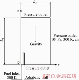
Figure 1 Schematic of physical model
As the maximum Reynolds number is only about 800, the laminar model is chosen for the gas flow. The steady state governing equations are shown below.
For continuity,
 (1)
(1)
For momentum,
 -
- (2)
(2)
For energy,
 (3)
(3)
For species,
 (4)
(4)
Equation of state,
 (5)
(5)
where �� denotes the velocity vector; ��, p, ��, T, cp, and �� represent density, pressure, dynamic viscosity, temperature, specific heat and thermal conductivity, respectively; hi, ��i, Yi, Di, DiT and Mi denote the enthalpy, production rate, mass fraction, molecular diffusion coefficient, thermal diffusion coefficient and molecular weight of species i, respectively; and R is the universal gas constant.
The multiple species diffusion model is applied to calculate species diffusion flux, in which thermal diffusion (Soret effect) is considered. The chemical reaction mechanism proposed by LI et al [21] is employed to simulate the combustion of hydrogen and air, while the Arrhenius law is adopted to calculate the chemical reaction rate. Thermal radiation is computed by the discrete order (DO) model and the surface emissivity is 0.92. Quartz is selected for the material of micro tube and hydrogen is chosen as fuel. The boundary conditions are specified as follows. At the tube inlet, the velocity of hydrogen flow is set, and the initial temperature is 300 K. Because of the low thermal conductivity of quartz glass (1.05 W/m��K), and meanwhile, the micro tube is relatively long and very thin, the heat dissipation from the bottom end of the tube is neglected. Thus, an adiabatic wall is set at the bottom, while the rest walls are specified as thermally coupled ones. A symmetry boundary is given to the central axis. All the rest boundaries are set to be pressure outlet with a gauge pressure of zero. The ambient fluid is air with a temperature of 300 K. The buoyancy is calculated through the following formula.
 (6)
(6)
where F denotes the buoyancy imposed on the gas of unit volume, ��L is the fluid density, while ���� denotes the air density at infinity and |g| is the abstract value of the acceleration of gravity.
The numerical simulation is performed on the Ansys Fluent platform using the double precision solver. Computation of the cold flow is conducted in advance. Then, combustion is initiated by setting a patch of 2000 K at the tube exit. The average gas temperature at the tube exit is monitored during the iteration process. When the monitored temperature remains invariant, and the residuals of mass, energy, momentum and species decline to 10-8, 10-7, 10-7 and 10-3, the convergence of iteration is considered to be reached.
2.2 Model validation
First, the grid independent of the numerical results is checked. Non-uniform structural grids are used in the numerical simulation. Specifically, fine grids are used near the tube and flame zone, while coarse grids are adopted in the region far from the flame. For comparison, we made computation under V=5 m/s and g=9.8 m/s2 using three sets of grid system (i.e., 50000, 100000, 200000). Comparison between the obtained axial temperature profiles shows that the differences of these results are very small. Thus, the grid system with 100000 meshes is chosen for the later computation.
Applying the present numerical model, we simulated the experimental cases investigated by ZHANG et al [15]. The flame height in Ref. [15] was defined based on OH distribution of the micro flame. The comparison between the predicted and measured flame heights under different jet velocities is depicted in Figure 2. It is shown that the mean error is about 6.4%, which confirms that reasonable accuracy can be expected in the present numerical simulation.
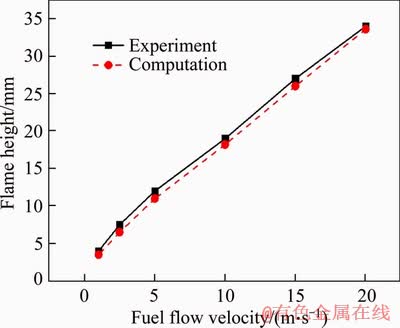
Figure 2 Comparison of flame height obtained through experiment and simulation under different jet velocities
3 Results and discussion
In the present study, we first scrutinize the buoyancy effect on the flame characteristics under V=0.1, 1, 5, 15 m/s. In fact, we also made computation for V=0.2-0.5m/s and found that V=0.1 m/s was the critical velocity. Therefore, only four cases are shown below. Then, the underlying mechanisms are revealed by analyzing two typical cases, i.e., V=5 and 0.1 m/s.
3.1 Buoyancy effect on flame under different jet velocities
Figure 3 shows the OH mass fraction (represents the flame structure of hydrogen) under four different jet velocities, i.e., V=0.1, 1, 5 and 15 m/s. It can be seen that in general, the flame height and width increase with an increasing jet velocity under both g=9.8 m/s2 and g=0. Moreover, compared to the case of g=0, both flame height and flame width under g=9.8 m/s2 decrease, which is consistent with the results found by SUNDERLAND et al [17]. In addition, other differences exist between the flame features under g=9.8 m/s2 and g=0. When V=0.1 m/s, the flame is attached to tube exit, exhibiting a solid oval shape. It is interesting to note that the peak OH mass fraction under g=9.8 m/s2 is lower than that under g=0, which is inverse to the other three cases. As the jet velocity is increased to 1 m/s, the flame is like a hollow ball that wraps the tube. GAO et al [16] also reported that, unlike a methane flame, the flame base of a hydrogen flame always attaches to the burner. Moreover, the OH mass fraction at the top is higher than that at the bottom, indicating that the combustion process is dominated by the buoyancy. When the jet velocity is further raised to 5 and 15 m/s, the flame is obviously prolonged, namely, the flame height is notably larger than the flame width. Furthermore, the OH mass fraction at the flame top is significantly decreased, implying that the combustion process is dominated by the inertia force.
Figure 4 illustrates the temperature fields under different jet velocities. Also, in each case, the left and right half represent the result under g=9.8 m/s2 and g=0, respectively. Similarly, the high temperature region expands with an increasing jet velocity under both g=9.8 m/s2 and g=0. This is because as the fuel flow rate is increased, the heat release amount will be augmented. Moreover, it is noted that for the same jet velocity, the high temperature region under g=9.8 m/s2 is narrower than that of g=0. Meawhile, the flame temperature (i.e., peak gas temperature) under g=0 is higher than that under g=9.8 m/s2. Comparing Figures 3 and 4, we discover that only at V=0.1 m/s, the flame temperature and peak OH mass fraction are both higher under g=0, whereas for V=1, 5, 15m/s the flame temperature and peak OH mass fraction are inconsistent (i.e., under g=9.8 m/s2, peak OH mass fraction is higher while flame temperature is lower). In addition, it should be pointed out that the flame temperature reaches up to 2300 K, which indicates that the fuel is well preheated by the inner wall before rushing out of the tube.
3.2 Analysis and discussion
3.2.1 Analysis of buoyancy effect at V=5 m/s
Figure 5 shows the streamlines in the computation domain under g=9.8 m/s2 (left) and g=0 (right). It can be clearly seen from Figure 5 that under g=9.8 m/s2, the gas in the central region rises and accelerates due to the buoyancy effect, entraining the surrounding air into the flame. Here, we define the radial flow rate as: m=�ѡ�V. Figure 6 presents a comparison between the radial flow rates from the left boundary at r=10 mm under g=9.8 m/s2 and g=0. Evidently, the radial flow rate under g=9.8 m/s2 is much greater than the counterpart under g=0. This means that more oxygen is supplied to the reaction zone. Meanwhile, the larger radial air flow rate also exerts a stronger compression effect on the flame front, which makes the flame thinner. It is worth pointing out that the axial air flow rate from the bottom boundary (although not shown here) is negligible compared to the radial flow rate. Therefore, the buoyancy effect on the flame structure is realized through the augmented radial flow rate of surrounding air. SUNDERLAND et al [17] also reported that buoyancy reduced the flame width via the effects of radial convection.
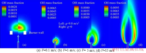
Figure 3 Comparison of OH mass fraction contours under different jet velocities:
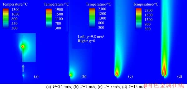
Figure 4 Comparison of temperature fields under different jet velocities:

Figure 5 Comparison of streamlines under g=9.8 m/s2 and g=0 for V=5 m/s
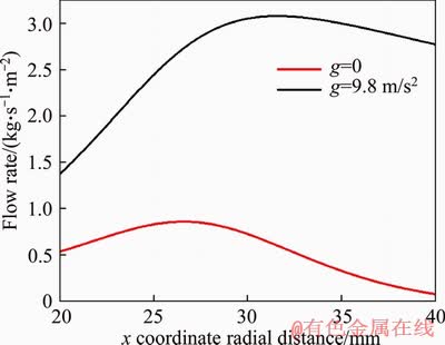
Figure 6 Comparison of air flow rate along radial direction across left boundary at r=10 mm under g=9.8 m/s2 and g=0 for V=5 m/s
As mentioned above, the radial air flow can compress the flame front from its outside. This will bring about a secondary effect on the fuel concentration field. In Figure 7, we present H2 mole fraction contours together with OH mass fraction contours. It can be seen that under g=9.8 m/s2, the hydrogen contours are denser, indicating a larger concentration gradient. As a result, the molecular diffusion flux is larger under g=9.8 m/s2, which can promote the mixing of fuel and air and thus intensify the combustion reaction [22-24].
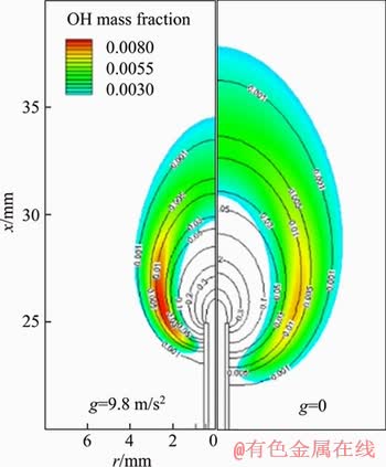
Figure 7 Comparison of H2 mole fraction contours (black lines) under g=9.8 m/s2 and g=0 for V=5 m/s. (Filled colored contours represent OH mass fraction)
As shown in Figure 3(c), the bottom of flame is located lower under g=0 than that under g=9.8 m/s2. Thus, a longer part of the micro tube is wrapped by the flame and a better preheating effect on hydrogen can be achieved under g=0. To confirm this, the axial profiles of gas temperature and inner wall temperature of the two cases are plotted in Figure 8. It can be seen that the inner wall temperature under g=0 is higher than that under g=9.8 m/s2, which leads to a better preheating effect on the hydrogen fuel. Specifically, the hydrogen temperature reaches 861 and 1241 K under g=9.8 m/s2 and g=0, respectively. From this point of view, the flame height and width should be smaller under g=0. However, this is inverse to the fact mentioned above, which demonstrates that the preheating effect plays a relatively weak role in the flame structure at large velocities.
Based on the above analysis, it can be concluded that when the jet velocity is relatively large, the differences in flame structure and temperature field under g=9.8 m/s2 and g=0 are dominated by the flow field, rather than the preheating effect. Namely, the buoyancy effect can create a strong radial flow towards the flame front,which changes the heat and mass transfer processes and eventually the reaction zone.
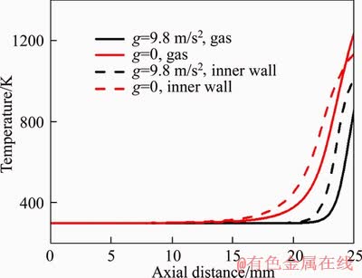
Figure 8 Comparison of axial profiles of gas temperature and inner wall temperature under g=9.8 m/s2 and g=0 for V=5 m/s
3.2.2 Analysis of buoyancy effect at V=0.1 m/s
Figure 9(a) shows the comparison between overall flow fields under g=9.8 m/s2 and g=0. Meanwhile, the local flow fields near the tube exit together with OH mass fraction contours are also compared in Figure 9(b). It is seen that the flow patterns are totally different under g=9.8 m/s2 and g=0. Specifically, the streamlines are convergent under g=9.8 m/s2 while divergent under g=0. As a result, the flame under g=9.8 m/s2 is blown off the tube rim and some fuel will leak out from the gap between flame root and tube rim. The combination effects of the inward cold air flow and the fuel leakage lead to the decrease in the heat release amount from the combustion process.
In Figure 10(a), we plot the profile of H2 mole fraction along the vertical direction of the outer tube wall (r=0.6 mm), while the corresponding profile along the top horizontal line of Figure 9(b) (x=26 mm) is plotted in Figure 10(b). It can be clearly seen that under g=9.8 m/s2, much more fuel leaks out from both radial and axial directions. This will lead to simultaneous decrease in combustion efficiency and flame temperature.
On the other hand, our calculation shows that the hydrogen temperatures are 1100 and 1170 K for the cases under g=9.8 m/s2 and g=0, respectively. This is because the heat loss from the fuel to the inner wall is less under g=0 than that under g=9.8 m/s2, as shown in Figure 11. Obviously, a larger heat loss rate under g=9.8 m/s2 is detrimental to the combustion process [25-30]. Since the total heat release amount is small at V=0.1 m/s, the above mentioned three aspects (i.e., cooling effect by inward air flow, fuel leakage and large heat loss rate) result in a decrease in both reaction intensity and flame temperature.
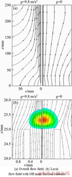
Figure 9 Comparison of streamlines under g=9.8 m/s2 and g=0 for V=0.1 m/s:
4 Conclusions
1) The role of buoyancy in jet hydrogen flames above a micro tube of 0.8 mm diameter was investigated through numerial simulation under four velocities (V=0.1, 1, 5, 15 m/s). The results demonstrate that when V��0.2 m/s, both flame height and width decrease under g=9.8 m/s2 compared to the case of g=0. Meanwhile, both OH mass fraction and heat release rate is increased under g=9.8 m/s2, whereas the flame temperature exhibts a decrease. In the case of very small jet velocity (e.g., V=0.1 m/s), both OH mass fraction and flame temperature are lower under g=9.8 m/s2 than the counterparts under g=0.
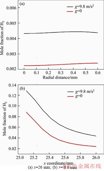
Figure 10 Comparison of H2 mole fraction profiles under g=9.8 m/s2 and g=0 for V=0.1 m/s:
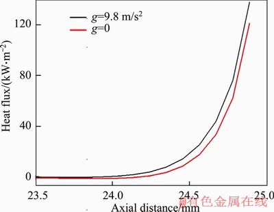
Figure 11 Comparison of heat flux along inner wall temperature of micro burner under g=9.8 m/s2 and g=0 for V=0.1 m/s
2) Analysis reveals that when the jet velocity is high, the hot gas in the central zone rises due to the buoyancy effect, entraining the surrounding cold air into the flame. This will compress the reaction zone and increase the hydrogen concentration gradient. As a result, the mixing of hydrogen and air will be promoted and the combustion will be intensified. However, due to the large amount of entrainment of cold air, the flame temperature will be slightly decreased under g=9.8 m/s2. For the case of very low jet velocity under g=9.8 m/s2, since the heat release amount is very small, the entrainment of cold air, fuel leakage from the tube exit rim and large heat loss rate lead to a decarese in both combustion intensity and flame temperature.
References
[1] FERNANDEZ-PELLO A C. Micro power generation using combustion: Issues and approaches [J]. Proceedings of the Combustion Institute, 2002, 29: 883-899. DOI: 10.1016/ S1540-7489(02)80113-4.
[2] WALTHER D C, AHN J. Advances and challenges in the development of power-generation systems at small scales [J]. Progress in Energy and Combustion Science, 2011, 37: 583-610. DOI: 10.1016/j.pecs.2010.12.002.
[3] E J Q, HUANG H J, ZHAO X H. Numerical investigations on effects of bluff body in flat plate micro thermophotovoltaic combustor with sudden expansion [J]. Journal of Central South University, 2016, 23: 975-982. DOI: 10.1007/s11771-016-3145-6.
[4] WAN J L, FAN A W, YAO H, LIU W. Experimental investigation and numerical analysis on the blow-off limits of premixed CH4/air flames in a mesoscale bluff-body combustor [J]. Energy, 2016, 113: 193-203. DOI: 10.1016/j.energy.2016.07.047.
[5] YANG W, LI L H, FAN A W, YAO H. Effect of oxygen enrichment on combustion efficiency of lean H2/N2/O2 flames in a micro cavity-combustor [J]. Chemical Engineering and Processes: Process Intensification, 2018, 127: 50-57. DOI: 10.1016/j.cep.2018.03.019.
[6] WANG S X, YUAN Z L, FAN A W. Experimental investigation on non-premixed CH4/air combustion in a novel miniature Swiss-roll combustor [J]. Chemical Engineering and Processes: Process Intensification, 2019, 139: 44-50. DOI: 10.1016/j.cep.2019.03.019.
[7] BAN H, VENKATESH S, SAITO K. Convection-diffusion controlled laminar micro flames [J]. Journal of Heat Transfer, 1994, 116(4): 954-959. DOI: 10.1115/1.2911471.
[8] IDA T, FUCHIHATA M, MIZUTANI Y. Microscopic diffusion flame structure with micro flames [C]// Proceedings of the Third International Symposium on Scale Modeling. Nagoya, Japan, 2000.
[9] MATTA L M, NEUMEIER Y, LEMON B, ZINN B T. Characteristics of microscale diffusion flames [J]. Proceedings of the Combustion Institute, 2002, 29: 933-939. DOI: 10.1016/S1540-7489(02)80118-3.
[10] FUJIWARA K, NAKAMURA Y. Experimental study on the unique stability mechanism via miniaturization of jet diffusion flames (microflame) by utilizing preheated air system [J]. Combustion and Flame, 2013, 160: 1373-1380. DOI: 10.1016/j.combustflame.2013.03.002.
[11] CHENG T S, CHEN C P, CHEN C S, LI Y H, WU C Y, CHAO Y C. Characteristics of micro jet methane diffusion flames [J]. Combustion Theory and Modelling, 2006, 10: 861-881. DOI: 10.1080/ 13647830600551917a.
[12] HIRASAWA T, SUMI M, NAKAMURA Y. Effect of burner size and material on extinction of methane diffusion microflame [J]. Journal of JSME, 2013, 13: 75-79. DOI: 10.11395/jjsem.13.s75.
[13] HOSSAIN A, NAKAMURA Y. Thermal and chemical structures formed in the micro burner of miniaturized hydrogen-air jet flames [J]. Proceedings of the Combustion Institute, 2015, 35: 3413-3420. DOI: 10.1016/ j.proci.2014.08.008.
[14] LI X, ZHANG J, YANG H, JIANG L Q, WANG X H, ZHAO D Q. Combustion characteristics of non-premixed methane micro-jet flame in coflow air and thermal interaction between flame and micro tube [J]. Applied Thermal Engineering, 2017, 112: 296-303. DOI: 10.1016/j.applthermaleng.2016.10.082.
[15] ZHANG J, LI X, YANG H, YANG H L, JIANG L Q, WANG X H, ZHAO D Q. Study on the combustion characteristics of non-premixed hydrogen micro-jet flame and the thermal interaction with solid micro tube [J]. International Journal of Hydrogen Energy, 2017, 42: 3853-3862. DOI: 10.1016/j.ijhydene.2016.07.255.
[16] GAO J, HOSSAIN A, NAKAMURA Y. Flame base structures of micro-jet hydrogen/methane diffusion flames [J]. Proceedings of the Combustion Institute, 2017, 36: 4209-4216. DOI: 10.1016/j.proci.2016.08.034.
[17] SUNDERLAND P B, MENDELSON B J, YUAN Z G, URBAN D L. Shapes of buoyant and nonbuoyant laminar jet diffusion flames [J]. Combust and Flame, 1999, 116: 376-386. DOI: 10.1016/S0010-2180(98)00045-5.
[18] SUNDERLAND P B, KRISHNAN S S, GORE J P. Effects of oxygen enhancement and gravity on normal and inverse laminar jet diffusion flames [J]. Combustion and Flame, 2004, 136: 254-256. DOI: 10.1016/j.combustflame.2003. 09.015.
[19] AALBURG C, DIEZ F J, FAETH G M, SUNDERLAND P B, YUAN Z G, URBAN D L. Shapes of non-buoyant round hydrocarbon-fueled laminar-jet diffusion flames in still air [J]. Combustion and Flame, 2005, 142: 1-16. DOI: 10.1016/j.combustflame.2004.12.009.
[20] ZHANG D, FANG J, GUAN J, WANG J W, ZENG Y, WANG J J, ZHANG Y M. Laminar jet methane/air diffusion flame shapes and radiation of low air velocity coflow in microgravity [J]. Fuel, 2014, 130: 25-33. DOI: 10.1016/j.fuel.2014.04.008.
[21] LI J, ZHAO Z W, KAZAKOV A, DRYER F L. An updated comprehensive kinetic model of hydrogen combustion [J]. International Journal of Chemical Kinetics, 2004, 36: 1-10. DOI: 10.1002/kin.20026.
[22] NING D G, LIU Y, XIANG Y, FAN A W. Experimental investigation on non-premixed methane/air combustion in Y-shaped mesoscale combustors with/without fibrous porous media [J]. Energy Conversion and Management, 2017, 138: 22-29. DOI: 10.1016/j.enconman.2017.01.065.
[23] XIANG Y, YUAN Z L, WANG S X, FAN A W. Effects of flow rate and fuel/air ratio on propagation behaviors of diffusion H2/air flames in a micro combustor [J]. Energy, 2019, 179: 315-322. DOI: 10.1016/j.energy.2019.05.052.
[24] LI L H, YUAN Z L, XIANG Y, FAN A W. Numerical investigation on mixing performance and diffusion combustion characteristics of H2 and air in planar micro-combustor [J]. International Journal of Hydrogen Energy, 2018, 43: 12491-12498. DOI: 10.1016/j.ijhydene. 2018.04.194.
[25] LIU L, ZHAO L, FAN A W. Effects of wall thickness and material on flame stability in a planar micro-combustor [J]. Journal of Central South University, 2019, 26: 2224-2233. DOI: 10.1007/s11771-019-4168-6.
[26] FAN A W, LI L H, YANG W, YUAN Z L. Comparison of combustion efficiency between micro combustors with single- and double-layered walls: A numerical study [J]. Chemical Engineering and Processes: Process Intensification, 2019, 137: 39-47. DOI: 10.1016/j.cep.2019.02.004.
[27] LI L H, WANG S X, ZHAO L, FAN A W. A numerical investigation on non-premixed catalytic combustion of CH4/(O2+N2) in a planar micro-combustor [J]. Fuel, 2018, 43: 12491-12498. DOI: 10.1016/j.fuel.2019.115823.
[28] XIANG Y, ZHAO M, HUANG H, FAN A W. Experimental investigation on the scale effects on diffusion H2/air flames in Y-shaped micro-combustors [J].International Journal of Hydrogen Energy, 2019, 44: 30462-30471. DOI: 10.1016/ j.ijhydene.2019.09.195.
[29] XIANG Y, WANG S X, YUAN Z L, FAN A W. Effects of channel length on propagation behaviors of non-premixed H2-air flames in Y-shaped micro combustors [J]. International Journal of Hydrogen Energy, DOI: 10.1016/ j.ijhydene.2019.11.147.
[30] YUAN Z L, FAN A W. The effects of aspect ratio on CH4/air flame stability in rectangular mesoscale combustors [J]. Journal of the Energy Institute, 2020, 93: 792-801. DOI: 10.1016/j.joei.2019. 05.003.
(Edited by FANG Jing-hua)
���ĵ���
��������������ɢ����Ӱ�����ֵģ���о�
ժҪ������ͨ����ֵģ��Ծ�ֹ������������������ĸ�����ЧӦ�������о��������ʾ���������ٶ���Խϴ�ʱ (V��0.2 m/s)�������������ٶ�(g=9.8 m/s2)�µĻ���߶ȡ����Ⱥ��¶Ⱦ�������������ʱС������OH����������ȴ�������������ٶȷdz�С(���磺V=0.1 m/s)ʱ�������������ٶ���OH���������ķ�ֵ�ͻ����¶Ⱦ�С������������ʱ�Ķ�Ӧֵ��������������V��0.2 m/sʱ�����ڸ�����ЧӦ���µľ��������ٽ���ȼ�������֮��Ļ�ϣ��Ӷ�ʹȼ�յõ�ǿ����Ȼ�������ڴ�������������뷴Ӧ���������¶����н��͡���V=0.1 m/sʱ����Ϊ���ͷ����ʷdz�С��������ľ����ȼ���ڹܿڱ�Ե��й¶���»����¶������½������ͬʱ������������ʱ��ȼ��������ڱڵ�ɢ����ʧ������ˣ��ܵ���˵�������ڷdz�С�������ٶ����Ǹ���ЧӦ��
�ؼ��ʣ�������ɢ���棻������ЧӦ������ṹ�������¶ȣ�����������Ԥ��ЧӦ
LIU Lei and ZHAO Ming contributed equally to this work
Foundation item: Project(51576084) supported by the National Natural Science Foundation of China
Received date: 2019-08-18; Accepted date: 2019-12-23
Corresponding author: FAN Ai-wu, PhD, Professor; Tel: +86-27-87542618; E-mail: faw@hust.edu.cn; ORCID: 0000-0003-1798-2154
Abstract: The buoyancy effect on micro hydrogen jet flames in still air was numerially studied. The results show that when the jet velocity is relatively large (V��0.2 m/s), the flame height, width and temperature decrease, whereas the peak OH mass fraction increases significantly under normal gravity (g=9.8 m/s2). For a very low jet velocity (e.g., V=0.1 m/s), both the peak OH mass fraction and flame temperature under g=9.8 m/s2 are lower than the counterparts under g=0 m/s2. Analysis reveals that when V��0.2 m/s, fuel/air mixing will be promoted and combustion will be intensified due to radial flow caused by the buoyancy effect. However, the flame temperature will be slightly decreased owing to the large amount of entrainment of cold air into the reaction zone. For V=0.1 m/s, since the heat release rate is very low, the entrainment of cold air and fuel leakage from the rim of tube exit lead to a significant drop of flame temperature. Meanwhile, the heat loss rate from fuel to inner tube wall is larger under g=9.8 m/s2 compared to that under g=0 m/s2. Therefore, the buoyancy effect is overall negative at very low jet velocities.
