
J. Cent. South Univ. (2016) 23: 1931-1936
DOI: 10.1007/s11771-016-3249-z

Exploring heating performance of gas engine heat pump with heat recovery
DONG Fu-jiang(������)1, LIU Feng-guo(�����)1, LI Xian-ting(����ͥ)2,
YOU Xue-yi(��ѧһ)3, ZHAO Dong-fang(�Զ���)1
1. School of Energy and Safety Engineering, Tianjin Chengjian University, Tianjin 300384, China;
2. School of Architecture, Tsinghua University, Beijing 100084, China;
3. School of Environmental Science and Engineering, Tianjin University, Tianjin 300072, China
 Central South University Press and Springer-Verlag Berlin Heidelberg 2016
Abstract:
In order to evaluate the heating performance of gas engine heat pump (GEHP) for air-conditioning and hot water supply, a test facility was developed and experiments were performed over a wide range of engine speed (1400-2600 r/min), ambient air temperature (2.4-17.8 ��C) and condenser water inlet temperature (30-50 ��C). The results show that as engine speed increases from 1400 r/min to 2600 r/min, the total heating capacity and energy consumption increase by about 30% and 89%, respectively; while the heat pump coefficient of performance (COP) and system primary energy ratio (PER) decrease by 44% and 31%, respectively. With the increase of ambient air temperature from 2.4 ��C to 17.8 ��C, the heat pump COP and system PER increase by 32% and 19%, respectively. Moreover, the heat pump COP and system PER decrease by 27% and 15%, respectively, when the condenser water inlet temperature changes from 30 ��C to 50 ��C. So, it is obvious that the effect of engine speed on the performance is more significant than the effects of ambient air temperature and condenser water inlet temperature.
Key words:
gas engine heat pump; coefficient of performance; primary energy ratio; heating mode; heat recovery��
1 Introduction
Nowadays, with the rapid development of economy and technology, the problems have increasingly come out, such as shortage of resources, environmental pollution and wastage of energy. For the past few years, the GEHP has been paid more attention in the heating, ventilation and air conditioning field because of its advangtage of improving the overall energy utilization efficiency and reducing the operating cost in running season [1]. The GEHP can recover the waste heat released by the engine cylinder jacket and exhaust gas and achieve the easy modulation of compressor speed through the software implementation [2]. In addition, the use of natural gas can ease the power shortage and achieve the goal of peaking and valley-filling. As a consequence, the GEHP has a different performance out of the ordinary electric driven heat pump in the heating mode in particular.
Many investigators focus on the performance characteristics of the GEHP used in heating mode using theoretical modeling and experimental approaches. Regarding the theoretical models for the GEHP system, a steady-state model was developed by ZHANG et al [1] in order to analyze the effect of both engine speed and ambient air temperature in heating mode. YANG et al [3] studied the dynamic characteristics of GEHP system on the heating performance based on an intelligent control simulation model. XU and YANG [4] developed a theoretical mathematical model with the waste heat recovery plant from the gas engine to control year-round room air humidity. SANAYE and CHAHARTAGHI [5] proposed a theoretical model to estimate the operating parameters of the GHEP under different operating conditions.
In regarding to the experimental studies of the GEHP system, ELGENDY et al [6] experimentally investigated the performance of a GEHP for hot water supply systems, which was characterized by water outlet temperatures, total heating capacity and primary energy ratio. YANG et al [7] studied the performance characteristics of a GEHP working as a water heater with R134a by simulation and experiment. WANG et al [8] bulit a parallel-type hybrid-power gas engine driven heat pump system and test the performance of the system in the heating conditions and cooling conditions. Recently, ELGENDY et al [9] compared performance characteristics of a GEHP under two different modes of heat recovery utilization experimentally at lower air ambient temperature.
The above review revealed that some experimental and theoretical investigations of the GEHP system performance are available in the literature. Furthermore, lots of researches are focused on the cooling performance of GEHPs [10-13]. However, there is still a lack of experimental data on the GEHP system in heating mode with engine heat recovery. In this work, a GEHP system test facility with R134a as a primary refrigerant is constructed and equipped with the necessary instruments. The effects of engine speed, ambient air temperature and condenser water inlet temperature on the GEHP performance are studied experimentally at various operating conditions in winter and spring. The research work provides useful information for system design improvement and energy efficient control strategy of GEHPs in the near future.
2 Experimental apparatus
Figure 1 shows the schematic diagram of the experimental apparatus, which consists of three circuits: heat pump working fluid circuit, engine coolant circuit and condenser water circuit. R134a is used as a primary working fluid while both air and ethylene glycol-water are used as secondary heat transfer fluids. Condenser water circuit is not described because of its obviousness.Here are the other two circuits.
The measurement points are also shown in Fig. 1. The locations are marked as T, F and p for temperature, flow rate and pressure, respectively. Pre-calibrated PT1000 sensors and LWY-25C water meter are used to measure operating temperature and condenser water flow rate. The gas flow rate is measured using DN20-type gas meter. What��s more, the pressure of refrigerant is measured by PP11 and PP30 sensors. A hygrothermograph is used to measure the ambient air parameters. All the measured data were monitored and recorded by software.
2.1 Heat pump working fluid circuit
Heat pump working fluid circuit includes a compressor, a condenser, an evaporator, an electronic expansion valve, a four-way valve, a gas-liquid separator, an oil separator, a liquid refrigerant reservoir, operational and safety control devices, and a set of well-insulated pipes. First of all, the refrigerant flows through the compressor which increases the pressure and temperature of the refrigerant. And the refrigerant becomes superheated vapor flowing into the oil separator and the four-way valve. Then the condenser water exchanges heat with the hot refrigerant; meanwhile the refrigerant is cooled and condensed to liquid. Flowing through the liquid refrigerant reservoir, the refrigerant discharged from the condenser enters the electronic expansion valve and expands into the evaporator. And in the evaporator, the refrigerant absorbs the heat from the ambient air and vaporizes. Finally, superheated refrigerant is sucked by the compressor via the four-way valve and the gas-liquid separator for the next cycle.
2.2 Engine coolant circuit
Engine coolant circuit includes a gas engine, an exhaust heat exchanger, an engine cylinder heat exchanger, a coolant pump, a hot water tank and a set of well-insulated pipes. The engine coolant, discharged from coolant pump is used to recover the engine waste heat from the engine cylinder heat exchanger and the exhaust gas heat from the exhaust gas heat exchanger.
The coolant flows through the engine cylinder heat exchanger and receives the engine waste heat to make sure that the engine can run steady and efficiently. Afterwards, the coolant is channeled into the exhaust gas heat exchanger to absorb heat from the exhaust gas and come back to hot water tank (2) for next cycle.
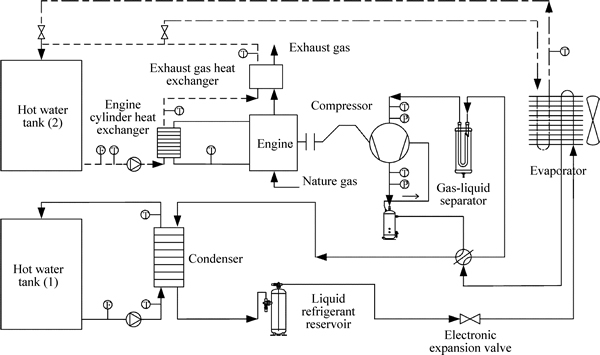
Fig. 1 Schematic diagram of experimental apparatus with measuring point locations
3 Data reduction
The heating capacity of the heat pump QH is calculated based on the measured condenser water mass flow rate and the water temperature difference at the condenser inlet and outlet as follows:
 (1)
(1)
where cp is specific heat capacity of condenser water at constant pressure; m1 is condenser water mass flow rate; and Tw1 and Tw2 are water temperature at the condenser inlet and outlet, respectively.
In the engine coolant circuit, the heat recovery QR consists of the engine waste heat Q1 and the exhaust gas heat Q2.The heat recovered from the engine cylinder and exhaust gas are calculated based on the coolant mass flow rate and temperature differences as follows:
 (2)
(2)
 (3)
(3)
 (4)
(4)
where m2 is engine cooling water mass flow rate; and Tcw1 and Tcw2 are engine cooling water temperature at the engine cylinder heat exchanger inlet and outlet; Tcw3 is engine cooling water temperature at the exhaust gas heat exchanger outlet.
The gas engine energy consumption QPE is calculated based on the natural gas volume flow rate Vg and low heating value, LHV, as follows:
 (5)
(5)
The compressor power W is the total energy consumption multiplied by a coefficient ��, which is obtained by actual measurement.
 (6)
(6)
The total heat capacity of the GEHP system is the sum of condenser heating capacity and heat recovery as follows:
 (7)
(7)
The COP of the heat pump and the PER of the GEHP system are calculated by
 (8)
(8)
 (9)
(9)
4 Results and discussions
All the experiments were done in heating mode with engine heat recovery at a wide range of engine speed (1400-2600 r/min), ambient air temperature (2.4-17.8 ��C) and condenser water inlet temperature (30-50 ��C) in this winter and spring. The influences of engine speed, ambient air temperature and condenser water inlet temperature on performance characteristics of the GEHP working with R134a are discussed in the next sections.
Figures 2-4 indicate the effect of engine speed on the performance of the GEHP while the effects of ambient air temperature and condenser water inlet temperature on the performance of the GEHP are presented in Figs. 5-8.
4.1 Effect of engine speed
Performance characteristics of GEHP as a function of engine speed are presented in Figs. 2-4. Figure 2 shows that the total heat capacity and energy consumption increase as engine speed increases from 1400 r/min to 2600 r/min with an ambient temperature of 5.8 ��C and condenser water inlet temperature of 50 ��C. Clearly, the energy consumption change is higher than that of the total heat capacity, which makes the heat pump COP and system PER sharply decrease as indicated in Figs. 3 and 4. As engine speed increases from 1400 r/min to 2600 r/min, the total heat capacity and energy consumption increase by about 30% and 89%, respectively, while the heat pump COP and system PER decrease by 44% and 31%.
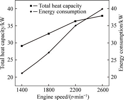
Fig. 2 Variations of total heat capacity and energy consumption with engine speed
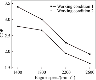
Fig. 3 Heat pump COP as a function of engine speed for different working conditions
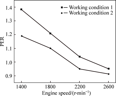
Fig. 4 System PER as a function of engine speed for different working conditions
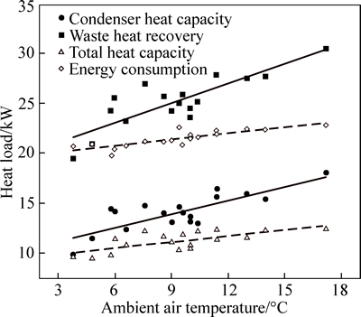
Fig. 5 Variations of heat loads with ambient air temperature
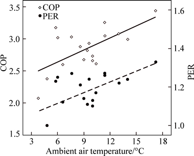
Fig. 6 Variations of heat pump COP and system PER with ambient air temperature

Fig. 7 Variations of heat loads with condenser water inlet temperature
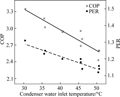
Fig. 8 Variations of heat pump COP and system PER with condenser water inlet temperature
Furthermore, from Fig. 2 we can find that the total heat capacity is smaller than energy consumption when engine speed is 2600 r/min. That is to say, under this circumstance, the primary energy ratio of the GEHP system is less than 1, which means the system is not energy-efficient. In addition, when running at high speed, the engine could make more noise [14]. Therefore, we should make the GEHP system running at low engine speed as far as possible.
However, the engine speed needs continuous regulation to meet the users�� demands in the operation process of the GEHP system. So, it��s vital to choose a wieldy engine speed for energy conservation and good economy.
4.2 Effect of ambient air temperature
In the heating mode, the finned tube heat exchanger acts as evaporator. So, the ambient air temperature makes a significant influence on the performance characteristics of the GEHP system. Figures 5-6 present the effects of ambient air temperature with an engine speed of 1400 r/min and condenser water inlet temperature of 40 ��C.
Figure 5 shows the variations of the heat loads with the ambient air temperature. We can see that the condenser heating capacity and waste heat recovery increase by 53% and 19% with the increase of the ambient air temperature varies from 2.4 ��C to 17.8 ��C, respectively. Clearly, the total heating capacity growth is higher than that of energy consumption. This is because that the elevated temperature of the ambient air makes the evaporation temperature go up and the refrigerant absorb more energy in the evaporator. As the ambient air temperature increases from 2.4 ��C to 17.8 ��C, the total heating capacity and energy consumption increased by 37% and 15%, respectively.
Figure 6 represents the variations of the heat pump COP and system PER with the ambient air temperature. It is evident from the figure that both of the heat pump COP and system PER at ambient air temperature of 17.8 ��C are higher than those at ambient air temperature of 2.4 ��C. This trend is attributed to the higher rate of increase in the condenser heating capacity and total heating capacity than energy consumption as shown in Fig. 5. As the ambient air temperature increases from 2.4 ��C to 17.8 ��C, the heat pump COP and system PER increase by 32% and 19%, respectively.
4.3 Effect of condenser water inlet temperature
Condenser water inlet temperature determines the water inlet and outlet temperature of the air-conditioning terminal. Figures 7-8 present the GEHP system performance characteristics at different condenser water inlet temperatures. The experiments are performed at an engine speed of 1400 r/min and ambient temperature of 6.0 ��C.
Figure 7 shows the variations of the heat loads with the condenser water inlet temperature. It is evident from this figure that the condenser heating capacity decreases by 27% while the waste heat recovery increased by 5.6%, as condenser water inlet temperature increases from 30 ��C to 50 ��C. In addition, we can obtain that the total heating capacity decreases and energy consumption increases with the rise of condenser water inlet temperature. Specifically, the total heating capacity decreases by 13.6% and the energy consumption increases by 8.4% when condenser water inlet temperature goes up from 30 ��C to 50 ��C. This was consistent with that reported for the standard heat pump system [15-16].
Figure 8 presents the variations of the heat pump COP and system PER with the condenser water inlet temperature. It is indicated that the heat pump COP and system PER decrease by 27% and 15%, respectively, as the condenser water inlet temperature varies from 30 ��C to 50 ��C. This trend can be inferred from the decrease in the total heating capacity and the increase in the energy consumption as shown in Fig. 7. In fact, as the condenser water inlet temperature increases, the refrigerant condensing temperature, condensing pressure and the compression ratio go up. As a consequence, both the compressor power consumption and engine fuel consumption increase. Hence, the heat pump COP and system PER reduce.
5 Error analysis
The condenser heating capacity and waste heat recovery are calculated from Eqs. (1), (3) and (4), which contain water mass flow rate multiplied by temperature difference. So, both condenser heating capacity and waste heat recovery are function of the two parameters.
 (10)
(10)
Gas engine energy consumption is calculated using Eq. (5) in which gas volume flow rate is multiplied by gas lower heating value (LHV).The gas lower heating value is used as a constant value during the experiments (36, 750 kJ/m3). The compressor power W is the total energy consumption multiplied by a coefficient ��. COP of the GEHP system is evaluated using Eq. (8) as a function of the condenser heating capacity and gas engine energy consumption. PER of the system is evaluated using Eq. (9) as a function of both total heating capacity and gas engine energy consumption. Therefore, the COP and PER can be estimated as a function of the following parameters.
 (11)
(11)
 (12)
(12)
The overall error eq of a quantity q indirectly evaluated from the measured values of the variables  can be calculated by:
 (13)
(13)
Equation (13) agrees with Gaussian law of error propagation in the case of linear dependence of the quantity q on  According to Eq. (13), the overall error of QH, QR, QPE, COP and PER are
 (14)
(14)
 (15)
(15)
 (16)
(16)
 (17)
(17)
where em is the error of the water mass flow rate measurements (3.3%); e��T represents the error of the temperature difference (2.5%); and eg is the error due to the gas volume flow rate measurements (1.6%). So, the overall errors of QH, QR, QPE, COP and PER are 4.14%, 4.14%, 1.60%, 4.44% and 6.07%, respectively.
6 Conclusions
1) The engine speed is found to be the most important parameter effecting on the heat pump COP and system PER. The heat pump COP and system PER decrease by 44% and 31% as a result of increasing engine speed from 1400 r/min to 2600 r/min. Therefore, we should make the GEHP system running at an appropriate low-speed on the premise of meeting the demand of users.
2) The effect of the ambient air temperature is also great significant to the performance characteristics of the GEHP. The heat pump COP and system PER decrease by 32% and 19%, respectively, as the ambient air temperature increases from 2.4 ��C to 17.8 ��C. So, it��s sensible to choose other sources instead of air when and where the air temperature is very low.
3) Moreover, the condenser water inlet temperature has also played a big part. As the condenser water inlet temperature increases from 30 ��C to 50 ��C, the heat pump COP and system PER decrease by 27% and 15%, respectively.
References
[1] Zhang R R, LU X S, LI S Z, LIN W S, GU A Z. Analysis on the heating performance of a gas engine driven air to water heat pump based on a steady-state model [J]. Energy Conversion and Management, 2005, 46: 1714-1730.
[2] COLOSIMO D D. Introduction to engine-driven heat pumps�� Concepts, approach, and economics [J]. ASHRAE Trans, 1987, 93(2): 987-996.
[3] Yang Zhao, Zhao Hai-bo, Fang Zheng. Modeling and dynamic control simulation of unitary gas engine heat pump [J]. Energy Conversion and Management, 2007, 48(12): 3146-3153.
[4] Xu Zhen-jun, Yang Zhao. Saving energy in the heat-pump air conditioning system driven by gas engine [J]. Energy and Buildings, 2009, 41(2): 206-211.
[5] Sanaye S, Chahartaghi M. Thermal modeling and operating tests for the gas engine-driven heat pump systems [J]. Energy, 2010, 35(1): 351-363.
[6] Elgendy E, Schmidt J, Khalil A, Fatouh M. Performance of a gas engine driven heat pump for hot water supply systems [J]. General Information, 2011, 36(5): 2883-2889.
[7] Yang Zhao, Wang Wen-bin, Wu Xi. Thermal modeling and operating tests for a gas-engine driven heat pump working as a water heater in winter [J]. Energy and Buildings, 2013, 58(2): 219-226.
[8] Wang Yan-wei, Cai Liang, Yu Yue, Zhang Xiao-song. Performance study of parallel-type hybrid-power gas engine-driven heat pump system [J]. Energy and Buildings, 2013, 62(5): 37-44.
[9] Elgendy E, Schmidt J. Optimum utilization of recovered heat of a gas engine heat pump used for water heating at low air temperature [J]. Energy and Buildings, 2014: 375-383.
[10] Elgendy E, Schmidt J. Experimental study of gas engine driven air to water heat pump in cooling mode [J]. General Information, 2010, 35(6): 2461-2467.
[11] Elgendy E, Schmidt J, Khalil A, Khalil A, Fatouh M. Performance of a gas engine heat pump (GEHP) using R410A for heating and cooling applications [J]. Energy, 2010, 35(12): 4941-4948.
[12] Kong X Q, Wang R Z, Wu J Y, Huang X H, Y H F, Wu D W, Xu Y X. Experimental investigation of a micro-combined cooling, heating and power system driven by a gas engine [J]. International Journal of Refrigeration, 2005, 28(7): 977-987.
[13] Sanaye S, Chahartaghi M, Asgari H. Dynamic modeling of gas engine driven heat pump system in cooling mode [J]. Energy, 2013, 55(1): 195-208.
[14] FANG Zheng, YANG Zhao, LIU Yun-tao, CHEN Yi-guang. Noise control of GEHP��s noise isolation device [J]. Journal of Vibration and Shock, 2009, 28(5): 192-198.
[15] Wang Xiao-tao, Ma Chong-fang, Lu Yuan-wei. An experimental study of a direct expansion ground-coupled heat pump system in heating mode [J]. International Journal of Energy Research, 2009, 33(15): 1367-1383.
[16] Brenn J, Soltic P, Bach C. Comparison of natural gas driven heat pumps and electrically driven heat pumps with conventional systems for building heating purposes [J]. Energy and Buildings, 2010, 42(6): 904-908.
(Edited by DENG L��-xiang)
Foundation item: Project(hx2013-87) supported by the Qingdao Economic and Technology Development Zone Haier Water-Heater Co. Ltd., China
Received date: 2015-04-22; Accepted date: 2015-09-21
Corresponding author: LIU Feng-guo, PhD; Tel: +86-13702045181; E-mail: fgliu@tju.edu.cn
Abstract: In order to evaluate the heating performance of gas engine heat pump (GEHP) for air-conditioning and hot water supply, a test facility was developed and experiments were performed over a wide range of engine speed (1400-2600 r/min), ambient air temperature (2.4-17.8 ��C) and condenser water inlet temperature (30-50 ��C). The results show that as engine speed increases from 1400 r/min to 2600 r/min, the total heating capacity and energy consumption increase by about 30% and 89%, respectively; while the heat pump coefficient of performance (COP) and system primary energy ratio (PER) decrease by 44% and 31%, respectively. With the increase of ambient air temperature from 2.4 ��C to 17.8 ��C, the heat pump COP and system PER increase by 32% and 19%, respectively. Moreover, the heat pump COP and system PER decrease by 27% and 15%, respectively, when the condenser water inlet temperature changes from 30 ��C to 50 ��C. So, it is obvious that the effect of engine speed on the performance is more significant than the effects of ambient air temperature and condenser water inlet temperature.
