
J. Cent. South Univ. (2017) 24: 840-853
DOI: 10.1007/s11771-017-3486-9

Dynamic analysis of spatial parallel manipulator with rigid and flexible couplings
LIU Shan-zeng(������)1, 2, DAI Jian-sheng(������)2, SHEN Gang(���)1, LI Ai-min(���)1,
CAO Guo-hua(�ܹ���)1, FENG Shi-zhe(������)1, MENG De-yuan(�ϵ�Զ)1
1. School of Mechatronic Engineering, China University of Mining and Technology, Xuzhou 221116, China;
2. King��s College, University of London, London WC2R 2LS, UK
 Central South University Press and Springer-Verlag Berlin Heidelberg 2017
Abstract:
The dynamics of spatial parallel manipulator with rigid and flexible links is explored. Firstly, a spatial beam element model for finite element analysis is established. Then, the differential equation of motion of beam element is derived based on finite element method. The kinematic constraints of parallel manipulator with rigid and flexible links are obtained by analyzing the motive parameters of moving platform and the relationships of movements of kinematic chains, and the overall kinetic equation of the parallel mechanism with rigid and flexible links is derived by assembling the differential equations of motion of components. On the basis of abovementioned analyses, the dynamic mechanical analysis of the spatial parallel manipulator with rigid and flexible links is conducted. After obtaining the method for force analysis and expressions for the calculation of dynamic stress of flexible components, the dynamic analysis and simulation of spatial parallel manipulator with rigid and flexible links is performed. The result shows that because of the elastic deformation of flexible components in the parallel mechanism with rigid and flexible links, the force on each component in the mechanism fluctuates sharply, and the change of normal stress at the root of drive components is also remarkable. This study provides references for further studies on the dynamic characteristics of parallel mechanisms with rigid and flexible links and for the optimization of the design of the mechanism.
Key words:
rigid and flexible couplings; parallel mechanism; finite element; force analysis; dynamic stress��
1 Introduction
The research on the dynamics of parallel manipulator has been widely concerned among Chinese and foreign researchers in recent years. However, since most of the researches on the dynamics of parallel manipulator are based on rigid components at present, the influence of the elastic deformation of components on the dynamic characteristics of the parallel mechanism is ignored [1-4]. The elastic deformations of components not only lead to the kinematic errors of moving platform and the elastic vibration or resonance of the whole mechanism, but also cause the degradation of the kinematic and dynamic performances of the parallel mechanism. Therefore, to understand the dynamic characteristics of high-speed and heavy-duty parallel mechanism, the influences of elasticity factors of components must be considered [5-11].
Since the manipulator at the terminal of parallel manipulator, the joint drive and matching devices are all installed on the moving platform or fixed base, the moving platform and fixed base feature high rigidities. For this reason, they are considered rigid bodies. However, linkages and joints are characterized by low rigidities and high flexibility, hence they should be considered flexible objects. Parallel mechanisms with the moving platform and fixed base being rigid bodies, and the linkages and joints in the chain of the system being flexible objects are referred to as parallel mechanisms with rigid and flexible couplings.
FATTAH et al [12, 13] proposed a finite element model with three degrees of freedom for flexible parallel manipulator to study the influence on accuracy exerted by the flexibility of moving components. PIRAS et al [14] employed the theory of finite element and KED analysis to study the dynamics of 3-PRR planar parallel manipulator with flexible links. The natural frequency of the system was analyzed.
The main subject of this study is the dynamic analysis (i.e., the inverse dynamics) of spatial parallel manipulator with rigid and flexible links. There are mainly three purposes of dynamic analysis for mechanisms, i.e., calculating the constraint reaction forces of kinematic pairs in the system, gaining knowledge of the shaking force and its moment on the frame by the mechanism, determining the input moment (or input force) on the input joint of the mechanism.
The spatial parallel manipulator with rigid and flexible couplings mostly works under the loads that change cyclically. The dynamic stress on components (or links) is large, and demonstrates sharp cyclical change, which can easily lead to the fatigue failure of components, or even low-level harmonic vibration or resonance sometimes. Therefore, the study on the dynamic stress of the components of parallel manipulator with rigid and flexible couplings is indispensable. The analysis on the dynamic stress of components is the foundation for understanding the failure mode and fatigue life of parallel manipulator with rigid and flexible couplings. On that account, the study is of great significance to the design of the mechanism and the development of control strategies for parallel manipulator with rigid and flexible couplings.
2 Dynamic equations
In general, parallel mechanism with rigid and flexible couplings is a nonlinear closed-loop dynamic mechanism with multiple flexible objects and rigid bodies, as shown in Fig. 1. The main procedure of establishing the dynamic model of parallel mechanism with rigid and flexible couplings based on its characteristics is shown as follows [15, 16].
1) According to finite element method, flexible components in the mechanism are classified as beam elements. Appropriate hypotheses of displacement or type functions are adopted, and generalized coordinates of beam elements are established;

Fig. 1 Schematic of parallel mechanism with rigid and flexible couplings
2) Kinetic energy and elastic potential energy of beam elements are deduced. The differential equations of motion of beam elements are obtained through the Lagrange��s equation;
3) Expressions of kinematic and dynamic constraints of the system are deducted from the kinematic and dynamic relationships between the terminals of kinematic chains and the moving platform;
4) Generalized coordinates of the whole mechanism are established. The differential equations of motion of kinematic chains are obtained by assembling the differential equations of motion of corresponding beam elements (as deducted in step 2)).
5) The dynamic equation of the parallel mechanism with rigid and flexible couplings is obtained by assembling the differential equations of motion of each kinematic chain and combining the kinematic and dynamic constraints of the system.
2.1 Beam element model of flexible links
The beam element model is established based on the structure of flexible components (or links) in parallel mechanism with rigid and flexible couplings. As shown in Fig. 2, nodes, A and B, are given in the beam element. ��=[��1, ��2, ��, ��18]T represents the vector of generalized coordinate of beam elements. ��1-��3 and ��10-��12 represent the elastic displacements at nodes. ��4-��6 and ��13-��15 represent the elastic angles at nodes. ��7-��9 and ��16-��18 represent curvatures at nodes. Coordinate system O-xyz of beam elements is established. For any points on the element, elastic displacements Wx(x,t), Wy(x,t) and Wz(x,t) along the x, y and z axes and elastic angular displacements ��x(x,t), ��y(x,t) and ��z(x,t) around x-axis, y-axis and z-axis can be expressed as the function of ��.

Fig. 2 Beam finite element model
According to the deformation characteristics and requirement on the precision of flexible components, the lateral elastic displacement, axial elastic displacement and elastic angular displacement around x-axis of beam elements are expressed by quintic Hermite interpolation function, linear interpolation function and cubic interpolation function, respectively. Then, the following results can be obtained based on the boundary conditions of generalized coordinate of the elastic deformation of elements.
 (1)
(1)
 (2)
(2)
 (3)
(3)
 (4)
(4)


where NA, NB, NC and ND are interpolation vectors, and each element is the function of x. The expressions are specified as follows.


 ;
;


where ni is the type function of displacements of elements (i = 1, 2, ��, 10); L is the length of element, and e is the relative coordinate with e equivalent to x/L.
In the movement of the system, the influence on rigid bodies brought by elastic deformation of beam elements is ignored because the displacement of beam element caused by elastic deformation is small. That is to say, the absolute velocity of a random point on beam element is considered the summation of the velocity of the movement of rigid body and the velocity of elastic deformation. Moreover, the absolute acceleration at a random point on beam element is considered the summation of the acceleration of the movement of rigid body and the acceleration of elastic deformation. Hence, the velocity of a random point with the coordinate of x on beam element is shown as follows:
 (5)
(5)
 (6)
(6)
 (7)
(7)
 (8)
(8)
where 
 and
and  are the absolute velocities of the given point on beam element along the x, y and z axes, respectively;
 and
and  are velocities of the moving rigid body along x, y and z axes, respectively, for a given point on beam element;
 and
and  are the velocities of elastic deformation of a given point on beam element along the x, y and z axis, respectively;
 and
and  are the absolute angular velocity, angular velocity of the rigid body and angular velocity of elastic deformation around x axis of a given point on beam element, respectively.
2.2 Differential equation of beam element
1) Kinetic energy of beam element
The kinetic energy of beam element is composed of the translational kinetic energy and the rotational kinetic energy around the axis, as shown below.

 (9)
(9)
where L is the length of beam element, and �� is the mass density of beam element; Ip is the polar moment of inertia of cross sections of beam element about x-axis. Moreover, m(x) is the function of mass distribution of beam element. For homogeneous beam element with uniform cross sections, m(x) equals ��A, where A is the cross-sectional area of beam element.
Equations (5)-(8) are substituted into Eq. (9), and the formula can be simplified as follows.
 (10)
(10)
where Me is the mass matrix of element, with

2) Elastic potential energy of beam element
The elastic potential energy of beam element consists of strain energy induced by bend, tension/ compression and torsion generated by bending moment, axial force and torque.

 (11)
(11)
where E and G are the elastic modulus of tension/compression, and shearing modulus of elasticity of the material, respectively; Iy and Iz are the principal moments of inertia of cross sections of beam element to y and z axes, respectively.
Equations (1)-(4) are substituted into Eq. (11), and the formula is simplified as follows.
 (12)
(12)
where Ke is the rigidity matrix of element, with


3) Differential equation of beam element
Equations (10) and (12) are substituted into Lagrange��s equation

The obtained differential equation of motion of beam elements is shown as follows.
 (13)
(13)
where Fe is the array of generalized force of external load of beam element. It includes concentrated nodal force and moment, and the equivalent nodal force of distributed force and moment. Virtual inertial load is not included, for all the forces and moments included are the external loads that really act on the element. Moreover, Pe is the array of forces on the studied beam element exerted by other beam elements connected with the studied one. Being internal forces for the whole mechanism, they counteract each other in the process of calculating the differential equation of motion of the whole system based on the equations of beam elements. is the array of inertia forces of rigid bodies of the system, which can be obtained by analyzing the motion of rigid bodies.
2.3 Kinematic and dynamic constraints
Because of the requirement of operating task, the rigidity of moving platform in parallel mechanism is generally much higher compared with the components of other kinematic chains. Therefore, the elastic deformation of moving platform can be ignored, namely, the moving platform is considered a rigid body. Spatial rigid body has six independent degrees of freedom. For that reason, the displacement of moving platform and the displacements of the joints of each chain are not independent; instead, they are the functions of six independent parameters of moving platform. The following conditions should be satisfied when they are coupled, namely, 1) the displacement of each joint of chains and the moving platform should be consistent with the displacement of the point on the moving platform where chains and the platform are jointed. 2) The sum of forces of all chains on the moving platform should be equal to the sum of external forces and inertia force of the moving platform.
1) Kinematic constraints
The six degrees of freedom of moving platform can be defined by three translational and three rotational variables of local moving coordinate system P-xyz along and around the coordinate system O-xyz, as shown in Fig. 3. Then the coordinate at point Pi (Pi represents the joint of moving platform and chains, and three joints are shown in Fig. 3, i.e., i=1, 2, 3) is function of the abovementioned six independent variables. The coordinate of point Pi (i=1, 2, 3) in the coordinate system P-xyz is a constant. It is supposed that the kinematic position of moving platform is at point P. The actual position changes slightly because of the elastic deformation of the components of chains in the system. (i.e., ����, ����, ����, ��xP, ��yP and ��zP), and finally moves to point P��. The z-y-x Euler angle of moving platform P1P2P3 is (��, ��, ��), and the coordinate of point P in coordinate system O-xyz is (xp, yp, zp)T. With the transformation matrix of coordinate system P-xyz to coordinate system O-xyz being and the transformation matrix of P'-x'y'z' to P-xyz being ��R, the approximate expression of ��R is as follows.
 (14)
(14)
In this case, the transformation matrix  of coordinate system P'-x'y'z' to O-xyz can be expressed as follows.
 (15)
(15)
Suppose the coordinates of points P1 and  as shown in Fig. 3 are
  and
and  in O-xyz, respectively.

Fig. 3 Coordination and constraint relationship between moving platform and chains
 (16)
(16)
where subscript O and P�� represent the projections in O-xyz and P'-x'y'z', respectively. Therefore, the following formula can be obtained.
 (17)
(17)
 (18)
(18)
Because all the position vectors of points in formula (18) are shown in coordinate system O-xyz, the subscripts can be omitted. Similarly, the functional relationship (angular displacements of point Pi (i=1, 2, 3) on the moving platform are equivalent to the angular displacement of the moving platform. The specific expression is omitted) between the displacements of P2 and P3 and six transformation parameters of the moving platform (i.e., ����, ����, ����, ��xP, ��yP and ��zP) can be obtained. The result is shown as follows after arrangement.
 (19)
(19)
The kinematic constraint between the moving platform and chains of parallel mechanism with rigid and flexible couplings is shown in formula (19).
2) Dynamic constraints
The moving platform is a rigid body. In coordinate system O-xyz, the kinematic equation of the moving platform can be obtained through Newton-Euler equation.

 (20)
(20)
where m0 is the mass of moving platform, and I3��3 is a 3'3 unit matrix.  is the product of rotational inertia and inertia of moving platform.
  and
and  are the external force applied on the moving platform and the moment of force, respectively.
  and
and  are the force applied on the moving platform by chains and the moment of force, respectively, where n is the number of chains.
The following result can be obtained by arranging kinematic Eq. (20) of moving platform.

 (21)
(21)
Equation (21) is the dynamic constraint of the system.
2.4 Dynamic equation of mechanism
The array U of generalized coordinates of the system is formed based on the established generalized coordinates of parallel mechanism. The differential equation of motion of each chain is obtained after assembling the differential equations of motion of corresponding elements. Then, the dynamic equation of the parallel mechanism with rigid and flexible couplings can be obtained by assembling the differential equations of motion of kinematic chains, and combining the kinematic constraint (as shown in Eq. (19)) and dynamic constraint (as shown in Eq. (21)).
 (22)
(22)
where U is the array of generalized coordinates of the system. M and K are the mass matrix and rigidity matrix, respectively.  is the damping matrix of the system, and l1 and l2 are Rayleigh damping coefficients. F is the array of generalized forces.
  is the array of accelerations of rigid bodies, and can be obtained through the kinematic analysis of rigid body of the mechanism.
  and
and  are the first and second derivatives of array U to time.
The array U of generalized coordinates of parallel mechanism can be obtained by calculating Eq. (22). Accordingly, kinematic and dynamic parameters of the mechanism such as the actual displacement, velocity, acceleration and track of motion are solved.
3 Force analysis of mechanism
The elastic displacement U and acceleration of elastic displacement of each coordinate in the system are obtained based on dynamic Eq. (22) of the parallel mechanism. After that, the elastic displacement �� and its acceleration  in corresponding coordinate system of elements are obtained through the transformation matrix between each coordinate system of elements and coordinate system of the whole mechanism. The elastic displacement �� and acceleration of elastic displacement of each element are substituted into Eq. (13), and the following formula can be obtained after arrangement.
 (23)
(23)
In the dynamic analysis of components of manipulator system, Pe is the array of forces applied on the studied component by other components connecting with the studied one. It is the data to be calculated. Fe is the array of generalized forces of external loads on components. Qe is the array of inertia forces of rigid bodies of system components, and can be obtained after conducting kinematic analysis on the rigid bodies of the system. Both Fe and Qe are considered to be known quantities. Therefore, the dynamic analysis of components can be performed after the elastic displacement �� and acceleration of elastic displacement of each component are obtained through elastodynamic analysis of the system.
For the purpose of simplifying the illustration, the 3-RRS parallel manipulator is adopted for the dynamic analysis of components. Figure 4 shows the schematic diagram of the mechanism. Fixed base B1B2B3 and moving platform P1P2P3 in the 3-RRS parallel manipulator are connected by three parallel chains BiCiPi (i=1, 2, 3). Moreover, the moving platform and each chain are connected by spherical pair (referred to as S pair), while the fixed base and each chain are connected by revolute pair (referred to as R pair). The axes of R pair at Ci (i=1, 2, 3) in each chain are parallel to the axes at Bi (i=1, 2, 3). The length values of component BiCi and CiPi are li1 and li2 (i=1, 2, 3), respectively. Coordinate system O-xyz is established, with the origin located at the geometric center of fixed base.

Fig. 4 Schematic diagram of 3-RRS parallel manipulator
Figure 5 displays the elastic displacements of chains in coordinate system of element. Figure 6 displays elastic displacements of chains in coordinate system of the whole mechanism. In Fig. 7, force analyses of component BiCi (i=1, 2, 3) and CiPi (i=1, 2, 3) in their corresponding coordinate systems of element are given. Component BiCi is considered cantilever beam.
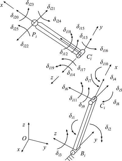
Fig. 5 Elastic displacements of chains in element coordinate

Fig. 6 Elastic displacements of chains in global coordinate

Fig. 7 Force analysis of chains
Chain B1C1P1 (i.e., i=1) is taken as an example for analysis and illustration. The solution to the vector of generalized coordinate of the system U can be obtained after solving the elastodynamic Eq. (22) of the system. Then the formula for calculating the vector of generalized coordinate U1 of chain B1C1P1 based on the vector of generalized coordinate of the system U is shown as follows.

 (24)
(24)
After obtaining the vector of generalized coordinate U1 of chain B1C1P1 based on Eq. (24), the solution to generalized coordinates of the system of components B1C1 and C1P1 is acquired accordingly (i.e., the transformation between matrices, please refer to literature [15]). Then the transformation between the generalized coordinates of the system of components B1C1 and C1P1 and their generalized coordinates of element can be expressed as follows.
 (25)
(25)
where  is the elastic displacement of component B1C1, with
  R18��1.
 (26)
(26)
where  is the elastic displacement of component C1P1, with
  R18��1.
The array of forces applied on component B1C1 by other components is  with the components of forces in the array shown in Fig. 7. The array of the forces applied on component C1P1 by other components is
  , and the components of forces are also shown in Fig. 7.


where 
 and
and  are the generalized forces corresponding to the curvature at node B1 of component B1C1.
 and
and  are the generalized forces corresponding to the curvature at node C1 of component B1C1.
 and
and  are the generalized forces corresponding to the curvature at node C1 of component C1P1.
 and
and  are the generalized forces corresponding to the curvature at node P1 of component C1P1. Moreover,
 and
and  are the forces applied on node B1 of component B1C1.
 and
and  are the moments on node B1 of component B1C1.
 and
and  are the forces applied to node C1 of component B1C1.
 and
and  are the moments on node C1 of component B1C1.
 and
and  are the forces applied on C1 of component C1P1.
 and
and  are the moments on node C1 of component C1P1.
 and
and  are the forces applied on node P1 of component C1P1.
 and
and  are the moments on node P1 of component C1P1.
The elastic displacement of component B1C1 (The calculation of acceleration of elastic displacement  is similar) calculated based on Eq. (25) is substituted into Eq. (23). By doing this,
  can be solved. In the same way, the elastic displacement and acceleration of elastic displacement
  of component C1P1 are substituted into Eq. (23), and then is solved.
In Fig. 7, 
 and
and  are the simplified components of known external forces at the centroid of component BiCi, and
 and
and  are those of CiPi.
 and
and  are the simplified moments of known external forces at the centroid of component BiCi, and
 and
and  are those of CiPi.

 and
and 

 are the forces and moments applied on node Bi of component BiCi by fixed base or the driver, and all of them are unknown. If component BiCi is the driver of the system, then the moment of driving force on BiCi applied by the system is equivalent to


 and
and 

 are the forces and moments applied on BiCi at node Ci by component CiPi, respectively. All of them are unknown (The friction of kinematic pair at node Ci is not considered, hence
  is acquired, which is not marked in Fig. 7, the same hereinafter).
Similarly, 

 and
and 

 are the forces and moments applied on component CiPi at node Ci by component BiCi. All of them are to be calculated (The friction of kinematic pair at node Ci is not considered, hence
  is acquired).

 and
and 

 are the forces and moments applied on component CiPi at node Pi by the moving platform. All of them are to be calculated (The friction of kinematic pair at node Pi is not considered, hence
 and
and can be concluded).
The diagram of force analysis at hinges of moving platform is shown in Fig. 8, where F0 is the principal vector of external forces applied on moving platform, including inertia force. M0 is the principal moment applied on the moving platform by external forces, including the moment of an inertia couple. The friction between kinematic pairs is not considered, hence the moment at kinematic pair Pi is zero. 
 and
and  (i=1, 2, 3) are the components of forces at kinematic pair Pi along the x, y and z axes in coordinate system O-xyz, respectively. The calculation of and (i=1, 2, 3) is conducted by using the kinetic equations of component CiPi under the coordinate system of the whole system based on the interaction between forces.

Fig. 8 Force analysis of moving platform
4 Dynamic stress of beam element
According to the solution to the elastodynamic equation of the mechanism, the dynamic stress (i.e., normal stress and shear stress) of flexible components in the system can be analyzed and calculated. It should be noticed that the dynamic stress of component is a function of its elastic deformation, but by solving the kinetic equation of flexible parallel manipulator, only the elastic deformations of nodes of components can be acquired. Therefore, to calculate the dynamic stress of element, the elastic deformation should be obtained through the elastic displacement of element.
In general, when elastic deformation is small, the degree of deformation and load have a linear relationship. Therefore, basic types of deformation are independent from each other. Due to the principle of physical independence of forces establishes, the superposition of forces can be used. For spatial parallel mechanism, components (rigid moving platform and fixed base are not included) show more than two types of basic deformation in the movement of the system. That is to say, the deformation of components is resultant deformation. A basic method for studying resultant deformations is to decompose them to basic deformations. Then the stress and deformation generated under each basic deformation are calculated separately. Finally, the stress and deformation of resultant deformation can be obtained by superposing the ones obtained under each basic deformation.
With respect to spatial beam elements with rectangular cross section (as shown in Fig. 9), the normal stress and shear stress (For rectangular cross sections, the hypothesis of plane cross section is still employed, and the influence of warp on cross sections during torsional deformation is ignored) of any point D on any cross section of beam elements can be expressed as follows.
 (27)
(27)

Fig. 9 Parameters of rectangular cross section
where
 ;
;
 ;
;
 ;
;

 ;
;
 ;
;
 is the vector of elastic deformation of beam element, and it is a function of time, with
  R18��1. Moreover, yD is the distance between any point D on the cross section of beam element and z-axis. zD is the distance between any point D on the cross section of beam element and y-axis. In addition, h and b are the thickness and width of beam element, respectively.
In terms of any moment during movement, the absolute values of the maximum normal stress and shear stress on any cross section of beam element are obtained based on Eq. (27).
 (28)
(28)
where
 ;
;
 ;
;
 .
.
The maximum normal stress and shear stress on any cross section (The value of x is no less than zero and no more than L) of the beam element at any moment during the movement of the mechanism can be obtained based on Eq. (28). After that, the values are compared one by one. By this means, the maximum normal stress  the maximum shear stress
  and the position of cross section where they are generated in the beam element can be acquired.
During the movement of the system, flexible components of parallel manipulator with rigid and flexible couplings bear resultant deformation of tension/compression, bend and torsion. The state of stress of components is very complicated. The failure criterion of material under complex stresses is investigated based on four strength theories frequently used in engineering, i.e., theory of the maximum tensile stress (the first strength theory), theory of the maximum tensional strain (the second strength theory), theory of the maximum shear stress (the third strength theory) and theory of deviator strain energy (the fourth strength theory). In general cases, brittle materials such as cast iron, stone and glass are damaged usually in the form of fracture, hence the first and second strength theories are applicable. Plastic materials such as carbon steel, copper and aluminum are mostly damaged in the form of flow, hence the third and fourth strength theories (Experimental results show that the fourth strength theory is closer to actual conditions) should be adopted. Because the materials of components of flexible parallel manipulator are basically plastic materials such as steel, copper and aluminum, the fourth strength theory is most appropriate for calculating the strength of components. Moreover, equivalent stress defined according to the fourth strength theory is one of the most objective indicators in finite element analysis. The equivalent stress of material defined based on the fourth strength theory is shown as follows.
 (29)
(29)
where ��1, ��2 and ��3 are three principal stresses of any given point (usually dangerous point) of the component, and they are arranged in the order of their algebraic values (not absolute values), namely, ��1 is equal to or greater than ��2, which is equal to or greater than ��3. ��s is the equivalent stress of material defined in accordance with the fourth strength theory.
For components bearing resultant deformation of tension/compression, bend and torsion, Eq. (29) can also be expressed as follows.
 (30)
(30)
where �� is the normal stress of any given point of the component, namely, the algebraic sum of the normal stress of tension/compression and that of bend; �� is the shear stress of any given point of the component.
5 Simulation of example
A 3-RRS spatial parallel mechanism with rigid and flexible couplings is used for simulation analysis, as shown in Fig. 4.
The parameters of the mechanism are shown as follows. The material is steel with the density (r) of 7800 kg/m3. The elastic modulus of tension/compression (E) is 2.1��1011 N/m2, and shear elastic modulus (G) is 8.0��1010 N/m2. The length of component BiCi (li1) and the length of component CiPi (li2) are both 0.15 m (i=1, 2, 3). The thickness of the rectangular cross section (h) is 1.5 mm and width (b) is 5 mm. The mass of moving platform (m0) is 0.152 kg, with r being 0.10 m and R being 0.12 m. The running time (T) is 1 s.
Operating task: The characteristics of motion of the moving platform are shown as follows:
 (31)
(31)
The expression of s(t) is shown as follows:
 0��t��T
The forces on components during the movement of 3-RRS parallel manipulator with rigid and flexible couplings can be calculated through numerical simulation. Figure 10 shows the curve of variation of (coordinates are shown in Fig. 5 and Fig. 7) the moment at kinematic pair Bi on component BiCi (i=1, 2, 3) under the forces around the y-axis in coordinate system Bi-xyz. For data analysis, please refer to Table 1. After analyzing the curves, it can be found that the moment at kinematic pair Bi fluctuates sharply because of the elastic deformation of components of flexible parallel manipulator. An example is that the maximum absolute value of moment MB3y is 0.224 6 N��m, twice the average absolute value of 0.105 3 N��m. This leads to the kinematic pair��s being easily shocked and worn, and the service life of flexible parallel manipulator being seriously affected. Therefore, this problem should be noted, and measures such as planning for the dynamics and optimization of design of the mechanism should be taken to improve the dynamic performances.
The curve of the variation of forces applied at B3 on component B3C3 is given in Fig. 11. It can be found that the forces along the axis on components are large, but those in other two directions are small through force analysis of 
 and
and  This phenomenon is closely related to the kinematic characteristics of the system. The forces on the components of flexible parallel manipulator in each direction exhibit remarkable changes because of the elastic deformation of components. Fierce fluctuations of forces in each direction can easily causethe fracture or fatigue failure of components. Moreover, sharp fluctuation of force on components easily leads to the shock and wear between kinematic pairs. It is also adverse to the stable operation of system and affects the accuracy of motion of the system, so solution to this problem should be proposed. In conclusion, force analysis of components lays a foundation for the design of parallel manipulator with rigid and flexible couplings.

Fig. 10 Curve of variation of moments:
Table 1 Data analysis of moments


Fig. 11 Curve of variations of force on component B3C3 at node B3:
The curves of the variation of the maximum dynamic stress (including the maximum normal stress  and the maximum shear stress
  at the root of component BiCi (i=1, 2, 3) in each chain are shown in Fig. 12 and Fig. 13. According to our analysis, in the whole process of movement of the system, the maximum normal stresses of driving components BiCi are all generated on the cross sections at the roots, and the maximum normal stress is much larger than the maximum shear stress of each driving component. The maximum dynamic stresses on driving components B1C1,B2C2 and B3C3 fluctuate obviously, which is closely related to the elastic deformation of flexible components and reciprocating motion of the system. Because of the elastic deformation of flexible components of parallel manipulator with rigid and flexible couplings, the kinematic precision of manipulator (moving platform) is degraded. Moreover, the moment of driving force of the system and dynamic stress of components increases obviously and fluctuates sharply. This poses a challenge to the highly precise movement and control strategies of the manipulator of parallel manipulator with rigid and flexible couplings. Obviously, in the movement of manipulator system, a certain degree of elastic vibration occurs on flexible components because of the effects of external loads and inertial forces of components, resulting in the elastic vibration of the whole system. In particular, under the condition of large loads and high velocity, the vibration becomes more fierce, seriously affecting the quality of operation of the manipulator.

Fig. 12 Curve of the maximum normal stress at root of component BiCi (i=1, 2, 3):

Fig. 13 Curve of the maximum shear stress at root of component BiCi (i=1, 2, 3):
The curve of the variation of normal stress �� at point (0, -b/2, h/10) (under coordinate system B2-xyz) on the cross section at the root of driving component B2C2 in the second chain of the system is shown in Fig. 14. Analysis indicates that during the whole process of movement of the system, the change of normal stress at the root of driving component B2C2 is significant. The values of normal stress vary greatly at different moments. On that account, conclusion can be drawn that in the movement of the system, the states of stress of parallel manipulator with rigid and flexible couplings are very complicated.

Fig. 14 Normal stress at root of component B2C2
The structure and kinematic characteristics of parallel manipulator with rigid and flexible couplings determine the state of stress of the system, as well as the alternating stress with varying amplitude that the components bear. With this being the case, the components can easily undergo sudden fracture or fatigue failure. Therefore, dynamic analysis of system is indispensable in the design and planning of motion for parallel manipulator with rigid and flexible couplings.
6 Conclusions
In this work, a spatial model for flexible beam element is established. The method and procedure of kinetic modeling for spatial parallel mechanism with rigid and flexible couplings are analyzed. Force analyses of components of parallel manipulator with rigid and flexible couplings are performed, and the formulase for the calculation of dynamic stress of components are deduced. Finally, the characteristics of forces on flexible components and the variation characteristics of dynamic stress of flexible components in parallel mechanism with rigid and flexible couplings are studied through the simulation of 3-RRS parallel manipulator with rigid and flexible couplings.
References
[1] LIU Shan-zeng, YU Yue-qing, SI Guo-ning, YANG Jian-xin, SU Li-ying. Kinematic and dynamic analysis of a three-degree-of- freedom parallel manipulator [J]. Journal of Mechanical Engineering, 2009, 45(8): 11-17.��in Chinese��
[2] ZHANG Ke-tao, FANG Yue-fa, GUO Sheng. Design analyses of a novel 3-DOF parallel mechanism [J]. Journal of Mechanical Engineering, 2009, 45(1): 68-72. (in Chinese)
[3] GAN Dong-ming, LIAO Qi-zheng, DAI Jian S, WEI Shi-min, SENEVIRATNE L D. Forward displacement analysis of the general 6�C6 Stewart mechanism using Gr bner bases [J]. Mechanism and Machine Theory, 2009, 44(9): 1640-1647.
[4] LIU Shan-zeng, ZHU Zhen-cai, SUN Zhao-peng, CAO Guo-hua. Kinematics and dynamics analysis of a three-degree-of-freedom parallel manipulator [J]. Journal of Central South University, 2014, 21(7): 2660-2666.
[5] LIU Shan-zeng, ZHU Zhen-cai, YU Yue-qing, LIU Chu-sheng, ZHANG Lian-jie. Frequency analysis of a spatial rigid-flexible coupling parallel manipulator [J]. Journal of Mechanical Engineering, 2011, 47(23): 39-48. (in Chinese)
[6] LIU Shan-zeng, YU Yue-qing, ZHU Zhen-cai, SU Li-ying, LIU Qing-bo. Dynamic modeling and analysis of a 3-RRS parallel manipulator with flexible links [J]. Journal of Central South University of Technology, 2010, 45(4): 12-15.
[7] ZHANG Jun, ZHAO Yan-qin. Elastodynamic modeling and joint reaction prediction for 3-PRS PKM [J]. Journal of Central South University, 2015, 22(8): 2971-2979.
[8] ZHANG Quan, MILLS JAMES K, CLEGHORN WILLIAM L, JIN Jia-mei, SUN Zhi-jun. Dynamic model and input shaping control of a flexible link parallel manipulator considering the exact boundary conditions [J]. Robotica, 2015, 33(6): 1201-1230.
[9] CHEN Zheng-sheng, KONG Min-xiu, JI Chen, LIU Ming. An efficient dynamic modelling approach for high-speed planar parallel manipulator with flexible links [J]. Proceedings of the Institution of Mechanical Engineers Part C-Journal of Mechanical Engineering Science, 2015, 229(4): 663-678.
[10] DU Zhi-jiang, SHI Ruo-chong, DONG Wei. Kinematics modeling of a 6-PSS parallel mechanism with wide-range flexure hinges [J]. Journal of Central South University, 2012, 19(9): 2482-2487.
[11] WANG Xiao-yun, MILLS J K. Dynamic modeling of a flexible-link planar parallel platform using a sub-structuring approach [J]. Mechanism and Machine Theory, 2006, 41(6): 671-687.
[12] FATTAH A, ANGELES J, MISRA A K. Dynamics of a 3-DOF spatial parallel manipulator with flexible links [C]// IEEE International Conference on Robotics and Automation. Nagoya, Piscataway: IEEE, 1995, 3(1): 627-632.
[13] FATTAH A, MISRA A K, ANGELES J. Dynamics of a flexible-link planar parallel manipulator in cartesian space [C]// ASME, Design Engineering Division, 20th Design Automation Conference. 1994, 69(2): 483-490.
[14] PIRAS G, CLEGHORN W L, MILLS J K. Dynamic finite-element analysis of a planar high-speed, high-precision parallel manipulator with flexible links [J]. Mechanism and Machine Theory, 2005, 40(7): 849-862.
[15] LIU Shan-zeng. Dynamics of 3-DOF spatial flexible parallel robots [D]. Beijing: Beijing University of Technology, 2009. (in Chinese)
[16] ZHAO Yong-jie, GAO Feng, DONG Xing-jian, ZHAO Xian-chao. Elastodynamic characteristics comparison of the 8-PSS redundant parallel manipulator and its non-redundant counterpart��the 6-PSS parallel manipulator [J]. Mechanism and Machine Theory, 2010, 45(2): 291-303.
(Edited by YANG Hua)
Cite this article as:
LIU Shan-zeng, DAI Jian-sheng, SHEN Gang, LI Ai-min, CAO Guo-hua, FENG Shi-zhe, MENG De-yuan. Dynamic analysis of spatial parallel manipulator with rigid and flexible couplings [J]. Journal of Central South University, 2017, 24(4): 840-853.
DOI:https://dx.doi.org/10.1007/s11771-017-3486-9Foundation item: Projects(2014QNB18, 2015XKMS022) supported by the Fundamental Research Funds for the Central Universities of China; Projects(51475456, 51575511) supported by the National Natural Science Foundation of China; Project supported by the Priority Academic Programme Development of Jiangsu Higher Education Institutions; Project supported by the Visiting Scholar Foundation of China Scholarship Council
Received date: 2015-10-16; Accepted date: 2016-03-13
Corresponding author: LIU Shan-zeng, Associate Professor; E-mail: liushanzeng@163.com
Abstract: The dynamics of spatial parallel manipulator with rigid and flexible links is explored. Firstly, a spatial beam element model for finite element analysis is established. Then, the differential equation of motion of beam element is derived based on finite element method. The kinematic constraints of parallel manipulator with rigid and flexible links are obtained by analyzing the motive parameters of moving platform and the relationships of movements of kinematic chains, and the overall kinetic equation of the parallel mechanism with rigid and flexible links is derived by assembling the differential equations of motion of components. On the basis of abovementioned analyses, the dynamic mechanical analysis of the spatial parallel manipulator with rigid and flexible links is conducted. After obtaining the method for force analysis and expressions for the calculation of dynamic stress of flexible components, the dynamic analysis and simulation of spatial parallel manipulator with rigid and flexible links is performed. The result shows that because of the elastic deformation of flexible components in the parallel mechanism with rigid and flexible links, the force on each component in the mechanism fluctuates sharply, and the change of normal stress at the root of drive components is also remarkable. This study provides references for further studies on the dynamic characteristics of parallel mechanisms with rigid and flexible links and for the optimization of the design of the mechanism.
