
Trans. Nonferrous Met. Soc. China 27(2017) 1224-1232
Effect of electromagnetic bulging on fatigue behavior of 5052 aluminum alloy
Du-zhen WANG1, Ning LI1, Xiao-tao HAN2, Liang LI2, Lin LIU1
1. School of Materials Science and Engineering, Huazhong University of Science and Technology, Wuhan 430074, China;
2. Wuhan National High Magnetic Field Center, Huazhong University of Science and Technology, Wuhan 430074, China
Received 3 March 2016; accepted 30 August 2016
Abstract:
The effect of electromagnetic bulging on the fatigue behavior of the 5052 aluminum alloy was investigated through tensile-tensile fatigue testing. The intriguing finding is that the bulged specimens exhibited enhanced fatigue strength as depicted by maximum stress vs the number of cycles until failure (S-N) curves, by comparison with these original aluminum alloys. Although the fatigue process of the original and budged alloys follows the same mechanism with three distinct steps, namely, crack initiation at a corner of the tested samples, stable crack propagation with typical fatigue striations and finally catastrophic fracture with dimple fractographic features. The typical crack propagation rate vs stress intensity factor range (da/dN-��K) curves derived from the spacing of striations reveal a lower crack propagation rate in the bulged specimens. The enhancement of fatigue strength in electromagnetically bulged aluminum alloy is further rationalized in-depth on the basis of strain hardening and dislocation shielding effect.
Key words:
fatigue behavior; aluminum alloy; electromagnetic bulging; dislocation;
1 Introduction
Lightweight design has attracted enduring attention in past decades due to the serious environmental problem and energy crisis. The substitution of conventional structural metals such as steel and cast iron by lightweight aluminum alloys thus becomes crucial in lightweight manufacturing. However, aluminum alloys intrinsically have poor formability comparing with these conventional mild steels, especially in traditional cold forming process, which seriously hinders the extensive application of aluminum alloys in modern industries. Electromagnetic forming (EMF), a high-speed forming process, is a revolutionized manufacturing technique with a series of superior properties such as high-speed, contactless forming, low springback, improved forming limit and high repeatability [1-7], thus exhibits alluring prospect in processing of aluminum alloy.
In the investigation of electromagnetic forming of aluminum alloys, the microstructural evolutions have become the major concerns due to its crucial importance to the formed component properties. For example, BACH et al [8,9] found that the electromagnetically formed aluminum sheet shows distinct dislocation cells with large disorientation boundaries and sub-grains due to the high strain rate of electromagnetic forming (which is estimated to be in the range of 103-104 s-1) [4,7], similar results were also observed by LI et al [10]. On the other hand, RISCH et al [11] reported that AA5182-type aluminum alloy after high-speed electromagnetic forming exhibited smaller grain size and more dislocation motion as compared to the alloy subjected to quasi-static deformation. Recently, LIU et al [12] studied the structure difference of 5052 aluminum alloy under electromagnetic forming and quasi-static tension, and found that electromagnetic forming could lead to stronger tendency of cross-slip of dislocations, higher dislocation density and more uniform dislocation configuration.
In our recent research [13], we systematically studied the microstructure, texture and mechanical properties of annealed 5052 aluminum alloy tubes subjected to electromagnetic bulging. The interesting finding is that the electromagnetic forming induces a significant increase in yield strength and fracture strength, but decrease in fracture elongation due to strain hardening effect resulting from the increase in dislocation density and the formation of high density dislocation bands. Whereas, whether these microstructural changes can impose an effect on the electromagnetically deformed aluminum alloys performance or serviceability or not, the research has scarcely been reported thus far, and the question is still unanswered. In the present work, the 5052 aluminum alloy plate was firstly deformed through high velocity electromagnetic forming, then the fatigue behavior of bulged specimens was analyzed via tensile-tensile fatigue testing, and compared with that of original (un-deformed) alloy. The maximum stress vs the number of cycles until failure (S-N) curves, the fracture morphologies and microstructural evolutions of the 5052 aluminum alloy with and without electromagnetic bulging were comparatively investigated to reveal the effect of pre-strain induced by electromagnetic bulging on fatigue behavior of 5052 aluminum alloy.
2 Experimental
The 5052 aluminum alloy plate in an annealed state with thickness of 3 mm [14-16] provided by the Southwest Aluminum Company (China) was used in the study. The plate was first cut into disks with outer diameter of 640 mm and inner diameter of 180 mm, and then subjected to electromagnetic bulging deformation.
The electromagnetic budging experiments were performed on the self-built electromagnetic forming system at Wuhan National High Magnetic Field Center, Huazhong University of Science and Technology, China. Figure 1(a) shows the schematic of the electromagnetic forming apparatus, it consists of a capacitor bank connected to the spiral coil which was placed at the center of the upper die seat, and the aluminum alloy sheet was placed above the die and positioned by the pins to keep coaxial with the coil. The workpiece, coil and die were assembled on the JH36-250 kN press. A power supply with a maximum storage capacity of 200 kJ was used for experiments. The total capacitor of the power supply is 640 ��F and the pulse width is 0.2-0.5 ms. The discharge voltage used in this work is 16 kV. The detailed process of the experiments was described elsewhere [17]. Upon discharging the capacitor, the time-varying current passes through the coil and generates a transient magnetic field, which induces an eddy current in the aluminum sheet and creates instantaneously an opposing transient magnetic field. The interaction of these two magnetic fields will create large repulsive Lorentz body forces to drive a rapid plastic deformation of aluminum sheets.
To evaluate the mechanical properties of the aluminum alloy in both original and electromagnetically bulged states, the specimens were cut from the section (see Fig. 1(b), wherein the deformation is relatively homogenous) and machined into dog-bone shapes with gauge length and width of 20 mm and 10 mm, respectively. The quasi-static tensile tests were performed with a constant strain rate of 1.0��10-3 s-1 at room temperature. According to the definition of strain rate:  (here
(here  is strain rate, l=20 mm is the gauge length of the sample), we calculated and set the loading rate dl/dt=1.2 mm/min in a universal testing machine (RGM-4050). The deformation of specimens was measured by using an extensometer. Standard tensile-tensile fatigue tests were conducted under load control using a sinusoidal waveform and a load ratio of R=0 (the ratio of minimum to maximum loads, herein the minimum load was set as zero). A nominal frequency of 7 Hz was employed using a computer-controlled, servo-hydraulic mechanical testing machine (QBS-50, China��s mark).
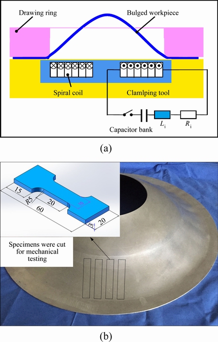
Fig. 1 Schematic drawing of electromagnetic forming apparatus (a) and sampling position and dimension of specimens (b) (unit: mm)
After fatigue test, the fracture morphologies of the aluminum alloy specimens with and without electromagnetic bulging were examined through scanning electron microscope (SEM, FEI Quanta 200). The detailed microstructures of the specimens were characterized through transmission electron microscope (TEM, FEI Tecnai G20). TEM thin foils were prepared by mechanical grinding to about 50 ��m in thickness, followed by a twin-jet polishing method in the electrolyte consisting of 30% (volume fraction) nitric acid and 70% methanol at the voltage of 16-20 V and temperature of -20 ��C.
3 Results
Figure 2 shows the microstructure features of both original and electromagnetically bulged aluminum alloy specimens characterized by TEM. Very few dislocations exist in the original specimen (see Fig. 2(a)), while lots of dislocation bands and walls can be observed in the electromagnetically bulged specimen (see Fig. 2(b)), indicating that the high speed electromagnetic forming process induced the generation of a large number of dislocations due to the plastic deformation (the measured thickness strain is about 3% for the chosen bulged specimens).
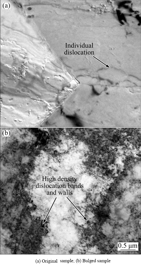
Fig. 2 Dislocation configuration before fatigue test
The general mechanical properties of the aluminum alloy with and without electromagnetically bulging were evaluated using quasi-static tension test, and the obtained stress-strain curves are depicted in Fig. 3. As compared to the original sample, the bulged one exhibits a strain hardening behavior as indicated by the increase in yield strength (��s) and maximum tensile stress (��b). For example, the values of ��s=(128��1.6) MPa, ��b=(216��1.3) MPa of the bulged sample are slightly higher than those of the original one (i.e., �ҡ�s=(101��0.9) MPa, �ҡ�b=(212��1.0) MPa), which is identical to the measured micro-hardness, i.e., a higher Vickers hardness (HV (74.8��1.8)) in the bulged sample than that of the original alloy (HV 65.2��1.6). However, the mean fracture strain decreases from (40.7��0.7)% in the original sample to (31.6��0.9)% in the bulged one. Though clear serrations caused by the Portevin-Le Chatelier (PLC) effect [18] in both stress-strain curves, little difference can be distinguished, even in the enlarged part as shown in the insert of Fig. 3.
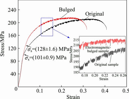
Fig. 3 Quasi-static tensile curves and magnification of selected area in plastic deformation region from each curve (labeled by green box)
The fatigue results of the original and bulged samples, plotted as S-N curve (the maximum stress vs the number of cycles until failure), are shown in Fig. 4. In general, the samples without visible crack initiation on the surface after 1.0��107 cycles were declared as the run-outs. From Fig. 4, the bulged aluminum alloy exhibits significant enhancement of fatigue performance, for example, the fatigue limit of bulged sample is about 130 MPa, which is 30% higher than that of the original aluminum alloy (100 MPa). In addition, the fatigue life of the bugled sample tested at ��max=130 MPa and 150 MPa are 30 and 8 times higher than that of the original aluminum alloy. It is also noted that the beneficial effects of the electromagnetic forming are more pronounced at a lower stress amplitude.
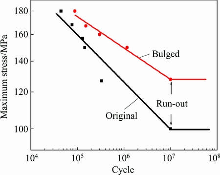
Fig. 4 S-N curves of original and bulged specimens
To probe the possible mechanisms of fatigue fracture for the electromagnetic-bulged alloy, the fracture morphologies after fatigue tests were characterized by SEM, as depicted in Fig. 5. Generally, the morphology of all the fractured samples is composed of three distinct regions, namely crack initiation region (labeled as region I), crack propagation region (labeled as region II) and fracture region (labeled as region III), as indicated in Fig. 5(a). It is evident that the fatigue crack initiates at the corner of the sample due to local stress concentration. The enlargement of the region II (see Fig. 5(b)) shows a few small crystallographic planes with various height and river patterns in the early propagation region, indicating that fatigue crack propagation is on different crystallographic planes in different grains via purely shearing [19,20]. Once fatigue crack propagation approaches a steady state, typical fatigue striations were observed in propagation region (i.e., region II), as shown in Fig. 5(c), in which secondary cracks along the fatigue striation can also be observed. Finally, fracture occurred and the fracture morphology in this region was characterized by typical dimple patterns, as shown in Fig. 5(d).
The above crack imitation-propagation-fracture process was also observed in the original 5052 aluminum alloy, as described in Fig. 6. In order to distinguish the difference of crack propagation behavior in the original and bulged aluminum alloy samples, the striation spacing (s) along the crack propagation direction with increasing crack length (a) was measured, the typical results at ��max=150 MPa are displayed in Fig. 7. It is essential that the striation spacings for both original and bulged samples increase with the crack propagation. The smaller striation spacing in the bulged sample than the original one at a certain crack length apparently indicates a lower crack propagation rate in the bulged specimen. This is in a good agreement to the result in the S-N curves.
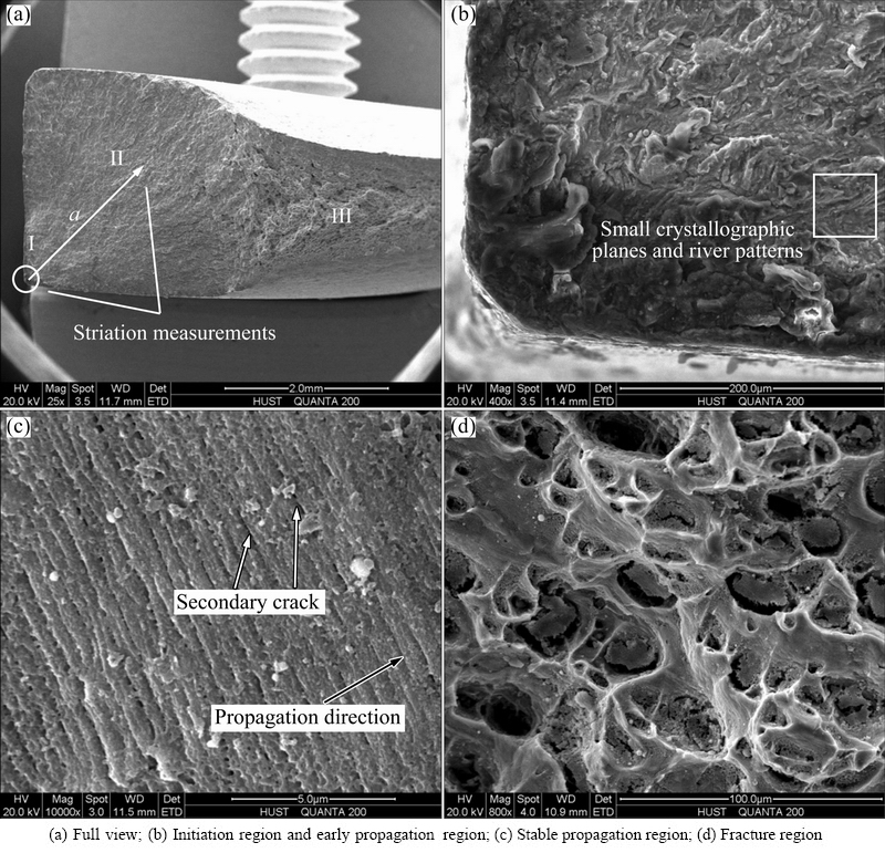
Fig. 5 Fractographs of bugled fatigue fracture sample at ��max=150 MPa
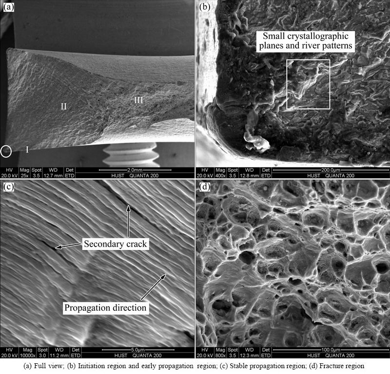
Fig. 6 Fractographs of original fatigue fracture sample at ��max=150 MPa
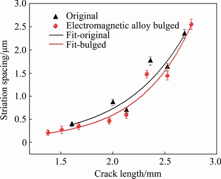
Fig. 7 Striation spacing at different positions at ��max=150 MPa
In order to further discover the possible effect of initial microstructure on the fatigue behavior, the microstructure of the original and bulged specimens at various fatigue stages were characterized by TEM, and the results are depicted in Fig. 8. With the increase of the stress amplitude, a clear transition of dislocation features from vein patterns (Fig. 8(a)) to cellular structures (Figs. 8(b) and (c)) for the original specimens indicates an enhanced contribution of secondary slip systems [21-26]. However, little difference can be detected between the original and electromagnetically- bulged aluminum alloy at the same stress amplitude (Figs. 8(d) and (e)).
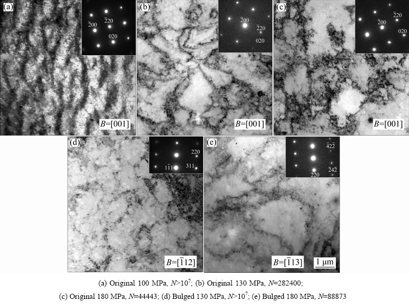
Fig. 8 TEM images showing dislocation arrangement of fatigue
4 Discussion
4.1 Low fatigue crack growth rate derived from small striation spacing
The above experimental results have exhibited that, by comparison with the original aluminum alloy, the electromagnetically bulged samples exhibit an enhanced fatigue performance. For example, the fatigue strength of the bulged sample increased by about 30 MPa as compared with the original alloy, and smaller fatigue striation spacing was observed in the bulged sample, which indicative of higher resistance to fatigue crack propagation. It is well known that striation features result from plastic blunting of crack tip on the basis of the double cross-slip theory [26,27], and each striation represents a step of crack propagation in one cycle, which essentially corresponds to the crack propagation rate (da/dN) under cyclic loading. Previous works [28,29] have reported a good agreement between the fatigue crack growth rate derived from the striation spacing and the direct measurements of the fatigue crack length as a function of the number of cycles. In order to investigate the difference of the crack propagation rate between the original and the bulged samples, the typical da/dN-��K curves (here ��K refers to the stress intensity factor range) are derived from a series of striation patterns obtained from SEM micrographs. Herein, the rate of crack propagation da/dN was determined by the average value of the fatigue striation spacing s [28], and ��K can be defined as [27]

 (1)
(1)
where K is stress intensity factor, smax and smin are the maximum stress and the minimum stress in one cycle, respectively; a is the crack length, �� is stress intensity factor correction and r is stress ratio. Considering that r=0 in the present work as mentioned above, then the equation (1) can be rewritten as
 (2)
(2)
Consequently, the correlation between da/dN and ��K can be expressed through the typical Paris function as [28]
da/dN=c(��K)n (3)
wherein c is a constant and n is the Paris exponent. The values of �� were referred to handbook and related literatures [30-32], then the relationship between da/dN and ��K for both original and electromagnetically bulged samples can be obtained, and the results are plotted in the double logarithm coordinates (see Fig. 9). It is notable that the values of da/dN in bulged specimens are lower than those in the original aluminum alloy, demonstrating a higher resistance to crack propagation, which is responsible for the enhanced fatigue limit, and consistent with the results as observed in Fig. 4.

Fig. 9 da/dN vs ��K plot for original and bugled specimens
4.2 Physical original of low crack propagation rate in EMF-bulged alloy
The question then arises as to why the electromagnetically bulged sample has a lower crack propagation rate than that of the original aluminum alloy. This phenomenon is similar to what was reported in pervious literatures [33-36], the authors regarded that the pre-deformation induces strain hardening that hampers materials flow. As a result, the nucleation and the propagation of the fatigue crack are delayed, and finally enhance the fatigue limit.
In general, the plastic energy absorbed in the plastic zone that forms ahead of the crack is proportional to the energy released during the crack propagation [37,38]. The rate of the crack can be expressed as [36]
 (4)
(4)
where ��p is the maximum stresses in the plastic zone that forms ahead of the crack, ��s is the yield strength, ��max is a maximum gross section stress and A1 is a constant. According to Eq. (4), the strain hardening behavior (corresponding to the increase in yield strength ��s) as shown in Fig. 3 indicates a reduce crack propagation rate, which results in an enhanced fatigue limit.
4.3 Dislocation shielding effect
The strain hardening is essentially related to the multiplication of dislocations during plastic deformation. In general, dislocation generation is a very chaotic process in which dislocations of all allowed Burgers vectors are formed. As a crack progresses through a material, in the plastic zone dislocations are generated with the necessary local geometric density to shield the crack [39]. In addition, in order for the crack and its geometric screening cloud to move uniformly, generation, motion and a large degree of annihilation of the real dislocations will be required. Because of the irreversibility of the deformation, a wake behind the crack is generated. The wake contains a large amount of stored and thermal energy; however, and since it is produced by the deformation field, it exerts an effective drag force on the geometric screening dislocations against their motion through the crystal. In these terms, the dislocation has a significant effect on the crack propagation.
The increase in dislocation density induced by the electromagnetic forming process, in turn, affects the stress field in front of crack tip and then reduces the local stress intensity, namely the dislocation shielding effect [39-41]. Figure 10 shows schematically the dislocation shielding effect due to the interaction between stress field generated by crack and the stress field caused by electromagnetic forming-induced dislocations.
According to the theory proposed by RICE and THOMSON [42], the local stress intensity factor k can be defined as
k=Kextra+Kexternal (5)
wherein Kexternal is the external stress intensity factor, Kextra is the extra stress intensity factor describing the interaction between the two stress fields as mentioned above. As for Mode I crack, Kextra of single dislocation is defined as
 (6)
(6)
where be is the edge component of the dislocation, E is the elastic modulus and �� is Poisson ratio, r is the distance between the tip of crack and dislocation, �� is the angle of crack propagation direction and the line of crack tip and dislocation, �� is the angle of the slip plane of dislocation and the propagation plane of crack. If the value of Kextra is negative, then k=Kextra+Kexternal<>external, in this case the dislocation shielding effect happens. According to typical plastic mechanics, the size of plastic zone of Mode I crack can be defined as [43]
 (7)
(7)
It is recipient that the pre-exist dislocations induced by electromagnetic forming process will affect the formation of the plastic deformation zone (PDZ) and the propagation of the crack. So, the extra stress intensity factor (Kextra) induced by the pre-exist dislocations in the plastic deformation zone can be calculated according to Eqs. (6) and (7).
By considering that the dislocation density (��) is uniform and �� equals to ��/4 in an ideal condition, and E=72 GPa, be=0.286 nm, ��=0.33 [44] and ��s=100 MPa, then the total extra stress intensity factor (Kextra,tol) in the plastic deformation zone can be calculated as
Kextra,tol=-9.52��10-8��Kexternal (8)
Equation (8) actually demonstrates that the value of Kextra is below zero and k=Kextra+Kexternal<>external. In this situation as mentioned above, the local stress intensity factor in front of crack tip can be reduced due to the interaction between stress field from crack tip and the stress field from pre-exist dislocations, this is the main reason that the crack propagation rate in the electromagnetically bulged samples is smaller than that in the original aluminum alloy. Our finding is essentially consistent with Kobayashi��s observations [45], they found that there are most edge dislocations in the plastic zone (for Mode I crack) with slip planes beyond the crack surface, whose motion finally leads to crack opening and blunting. Therefore, one can image that the increase of dislocation density in front of crack tip will impede crack propagation, and finally results in a smaller striation spacing, lowers crack propagation rate and enhances fatigue performance, as already observed in Fig. 4.
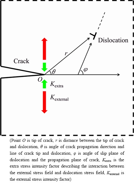
Fig. 10 Schematic diagram of dislocation shielding effect
5 Conclusions
1) The fatigue limit of the bulged specimens increases by 30% over the original aluminum alloy.
2) The striation spacing in the stable crack propagation in the bulged specimen is smaller than that in the original alloy, demonstrating a higher resistance to fatigue crack propagation in the bulged specimens.
3) The crack propagation rate da/dN as a function of the stress intensity factor range ��K indicates that the crack propagation rate in bulged specimens is lower than that in the original aluminum alloy.
4) The enhancement of the fatigue strength and the increase of the resistance to fatigue crack propagation in the electromagnetically bulged aluminum alloy are caused by strain hardening and dislocation shielding effect.
Acknowledgement
The authors are grateful to the Analytical and Testing Center (Huazhong University of Science and Technology) for technical assistance.
References
[1] IRIONDO E, GONZALEZ B, GUTIERREZ M, VONHOUT V, DAEHN G, HAYES B. Electromagnetic springback reshaping [C]//Proceedings of the 2nd International Conference on High Speed Forming. Dortmund, Germany: Technical University of Dortmund, 2006: 153-160.
[2] IMBERT J M, WINKLER S L, WORSWICK M J, OLIVEIRA D A. The effect of tool�Csheet interaction on damage evolution in electromagnetic forming of aluminum alloy sheet [J]. Journal of Engineering Materials and Technology, 2005, 127(1): 145-153.
[3] THOMAS J D, SETH M, DAEHN G S, BRADLEY J R, TRIANTAFYLLIDIS N. Forming limits for electromagnetically expanded aluminum alloy tubes: Theory and experiment [J]. Acta Materialia, 2007, 55(8): 2863-2873.
[4] ALTYNOVA M, HU Xiao-yu, DAEHN G S. Increased ductility in high velocity electromagnetic ring expansion [J]. Metallurgical and Materials Transactions A, 1996, 27(7): 1837-1844.
[5] GOLOVASHCHENKO S F. Material formability and coil design in electromagnetic forming [J]. Journal of Materials Engineering and Performance, 2007, 16(3): 314-320.
[6] OLIVEIRA D A, WORSWICK M J, FINN M, NEWMAN D. Electromagnetic forming of aluminum alloy sheet: free-form and cavity fill experiments and model [J]. Journal of Materials Processing Technology, 2005, 170(1): 350-362.
[7] PSYK V, RISCH D, KINSEY B L, TEKKAYA A E, KLEINER M. Electromagnetic forming��A review [J]. Journal of Materials Processing Technology, 2011, 211(5): 787-829.
[8] BACH F W, WALDEN L, KLEINER M, RISCH D. Effects of electromagnetic and hydraulic forming processes on the microstructure of the material [C]//Proceedings of the 1st International Conference on High Speed Forming. Dortmund, Germany: Technical University of Dortmund, 2004: 57-70.
[9] BACH F W, BORMANN D, WALDEN L. Influence of forming rate on the microstructure and properties of materials subjected to electromagnetic forming-A synopsis [C]//Proceedings of the 3rd International Conference on High Speed Forming. Dortmund, Germany: Technical University of Dortmund, 2008: 55-64.
[10] LI Zhi-gang, LI Ning, JIANG Hua-wen, XIONG Yuan-yuan, LIU Lin. Deformation texture evolution of pure aluminum sheet under electromagnetic bulging [J]. Journal of Alloys and Compounds, 2014, 589: 164-173.
[11] RISCH D, GERSTEYN G, DUDZINSKI W, BEERWALD C, BROSIUS A, SCHAPER M, TEKKAYA A E, BACH F W. Design and analysis of a deep drawing and in-process electromagnetic sheet metal forming process [C]//Proceedings of the 3rd International Conference on High Speed Forming. Dortmund, Germany, 2008: 201-212.
[12] LIU Da-hai, YU Hai-ping, LI Chun-feng. Comparative study of the microstructure of 5052 aluminum alloy sheets under quasi-static and high-velocity tension [J]. Materials Science and Engineering A, 2012, 551: 280-287.
[13] JIANG Hua-wen, LI Ning, XU Zhu, FAN Zhi-song, YU Hai-ping, LIU Lin. Microstructure, texture and mechanical properties of 5A02 aluminum alloy tubes under electromagnetic bulging [J]. Materials & Design, 2015, 82: 106-113.
[14] XU Zhu, LI Ning, JIANG Hua-wen, LIU Lin. Deformation nanotwins in coarse-grained aluminum alloy at ambient temperature and low strain rate [J]. Materials Science and Engineering A, 2015, 621: 272-276.
[15] YAN Cong, LI Ning, JIANG Hua-wen, WANG Du-zhen, LIU Lin. Effect of electropulsing on deformation behavior, texture and microstructure of 5A02 aluminum alloy during uniaxial tension [J]. Materials Science and Engineering A, 2015, 638: 69-77.
[16] LU Bai-ping, LI Ning. Versatile aluminum alloy surface with various wettability [J]. Applied Surface Science, 2015, 326: 168-173.
[17] LUO Wen-yong, HUANG Liang, LI Jian-jun, LIU Xian-long, WANG Zhi-qiang. A novel multi-layer coil for a large and thick-walled component by electromagnetic forming [J]. Journal of Materials Processing Technology, 2014, 214(11): 2811-2819.
[18] PARK D Y, NIEWCZAS M. Plastic deformation of Al and AA5754 between 4.2 K and 295K [J]. Materials Science and Engineering A, 2008, 491(1): 88-102.
[19] ZHAI Tong-guang, WILKINSON A J, MARTIN J W. A crystallographic mechanism for fatigue crack propagation through grain boundaries [J]. Acta Materialia, 2000, 48(20): 4917-4927.
[20] CHEN Yuan-yuan, ZHENG Zi-qiao, CAI Biao, XU Jian-qiu, SHE Ling-juan, LI Hai. Initiation and propagation behavior of fatigue cracks in 2197 (Al-Li)-T851 alloy [J]. Rare Metal Materials & Engineering, 2011, 40(11):1926-1930
[21] SEGALL R L, PARTRIDGE P G. Dislocation arrangements in aluminium deformed in tension or by fatigue [J]. Philosophical Magazine, 1959, 4(44): 912-919.
[22] CHICOIS J, FOUGERES R, GUICHON G, HAMEL A, VINCENT A. Mobilite des dislocations lors de la sollicitation cyclique de l'aluminium polycristallin [J]. Acta Materialia, 1986, 34: 2157-2170.
[23] EL-MADHOUN Y, MOHAMED A, BASSIM M N. Cyclic stress�Cstrain response and dislocation structures in polycrystalline aluminum [J]. Materials Science and Engineering: A, 2003, 359(1): 220-227.
[24] MOHAMED A O, EL-MADHOUN Y, BASSIM M N. Dislocation boundary width changes due to cyclic hardening [J]. Metallurgical and Materials Transactions A, 2006, 37(12): 3441-3443.
[25] FUJII T, WATANABE C, NOMURA Y, TANAKA N, KATO M. Microstructural evolution during low cycle fatigue of a 3003 aluminum alloy [J]. Materials Science and Engineering A, 2001, 319: 592-596.
[26] SURECH S. Fatigue of materials [M]. London: Cambridge University Press, 1993: 200
[27] SCHIJVE J. Fatigue of structures and materials [M]. Dordrecht: Kluwer Academic, 2001.
[28] DE MATOS P F P, MCEVILY A J, MOREIRA P, MOREIRAA P M G P, DE CASTROA P M S T. Analysis of the effect of cold-working of rivet holes on the fatigue life of an aluminum alloy [J]. International Journal of Fatigue, 2007, 29(3): 575-586.
[29] NIX K J, FLOWER H M. Advances in fracture research [C]// Proceedings of the 5th International Conference on Fracture. Cannes, France: Pergamon Press, 1981.
[30] China Aviation Academy. Stress intensity factor handbook [M]. Beijing: Science Press, 1981. (in Chinese)
[31] ROOKE D P, CARTWRIGHT D J. Compendium of stress intensity factors [M]. London: His Majesty��s Stationery Office, 1976.
[32] RANDALL P N, BROWN W F Jr, STRAWLEY J E. ASTM STP 410 [S]. 1966.
[33] FUJIMURA K, NISITANI H, FUKUDA S. Changes in residual stress and successive observations by electron microscope in the fatigue test of prestrained or shot-peened carbon steel [J]. Transactions of the Japan Society of Mechanical Engineering, 1993, 59(568): 3006-3013. (in Japanese)
[34] NISITANI H, TERANISHI T, TAKENO T. Effect of pre-strain on notched fatigue strength of 0.45% C steel [J]. Journal of the Japan Society of Mechanical Engineers, Series A, 1998, 64(626): 2502-2507. (in Japanese)
[35] FROST N E. The effect of cold work on the fatigue properties of two steels [J]. Metallugia, 1960, 62: 85-90.
[36] RADHAKRISHNAN V M, BABURAMANI P S. An investigation of the effect of pre-straining on fatigue crack growth [J]. Materials Science and Engineering, 1975, 17(2): 283-288.
[37] GALLINA V, GALOTTO CP, RUSPA G. Crack propagation during fatigue experiments [J]. International Journal of Fracture Mechanics, 1970, 6(1): 21-31.
[38] VALLURI S R. Some recent developments at ��GALCIT�� concerning a theory of metal fatigue [J]. Acta Metallurgica, 1963, 11(7): 759-775.
[39] THOMSON R M, SINCLAIR J E. Mechanics of cracks screened by dislocations [J]. Acta Metallurgica, 1982, 30(7): 1325-1334.
[40] L I J C M. Dislocation modellingofphysicalsystem [M]. New York: Pergamon Press, 1981.
[41] CHEN Jian-qiao. Strength of engineering materials [M]. Wuhan: Huazhong University of Science and Technology Press, 2008. (in Chinese)
[42] RICE J R, THOMSON R. Ductile versus brittle behaviour of crystals [J]. Philosophical Magazine, 1974, 29(1): 73-97.
[43] Compile Group of Mechanical Property of Metal. Mechanical property of metal [M]. Beijing: China Machine Press, 1982. (in Chinese)
[44] ZHOU Yu, WU Gao-hui. Analysis methods in materials science [M]. Harbin: Harbin Institute of Technology Press, 2007. (in Chinese)
[45] KOBAYASHI S, OHR S M. Dislocation arrangement in the plastic zone of propagating cracks in nickel [J]. Journal of Materials Science, 1984, 19(7): 2273-2277.
������ζ�5052���Ͻ�ƣ����Ϊ��Ӱ��
������1���� ��1������2���� ��2���� ��1
1. ���пƼ���ѧ ���Ͽ�ѧ�빤��ѧԺ���人 430074��
2. ���пƼ���ѧ �人��������ǿ�ų����ģ��人 430074
ժ Ҫ��Ϊ���о�������μ��������Ͻ�ƣ����Ϊ��Ӱ�죬�Ե�����κ��5052���Ͻ���������ƣ�������о���ƣ��Ӧ��-�������߽�������������ԭʼ������������κ��ƣ������ƣ��ǿ�����������ӡ�����ɨ����������ԶϿ���ò���з�����������������������£�ƣ�����ƶ������ڴ���Ӧ�����еı߽Ǵ�������������չ�������˵��͵�ƣ�ͻ��ƺ����ѽṹ���ԱȲ�ͬλ�õ�ƣ�ͻ��ƿ��Ȳ�����������չ���ʣ��ɴ˵õ���������չ�������߱���������κ�����ƣ��������չ���ʽ��͡����۷�������ƣ��ǿ�ȵ������Ҫ�����ڵ�����������Ӧ��Ӳ����λ���ܶ����Ӷ����Ƽ�˵�����ЧӦ��
�ؼ��ʣ�ƣ����Ϊ�����Ͻ𣻵�����Σ�λ��
(Edited by Xiang-qun LI)
Foundation item: Project (2011CB012806) supported by the National Basic Research Program of China
Corresponding author: Lin LIU; Tel: +86-27-87556894; E-mail: lliu2000@mail.hust.edu.cn
DOI: 10.1016/S1003-6326(17)60143-2
Abstract: The effect of electromagnetic bulging on the fatigue behavior of the 5052 aluminum alloy was investigated through tensile-tensile fatigue testing. The intriguing finding is that the bulged specimens exhibited enhanced fatigue strength as depicted by maximum stress vs the number of cycles until failure (S-N) curves, by comparison with these original aluminum alloys. Although the fatigue process of the original and budged alloys follows the same mechanism with three distinct steps, namely, crack initiation at a corner of the tested samples, stable crack propagation with typical fatigue striations and finally catastrophic fracture with dimple fractographic features. The typical crack propagation rate vs stress intensity factor range (da/dN-��K) curves derived from the spacing of striations reveal a lower crack propagation rate in the bulged specimens. The enhancement of fatigue strength in electromagnetically bulged aluminum alloy is further rationalized in-depth on the basis of strain hardening and dislocation shielding effect.
[26] SURECH S. Fatigue of materials [M]. London: Cambridge University Press, 1993: 200
[27] SCHIJVE J. Fatigue of structures and materials [M]. Dordrecht: Kluwer Academic, 2001.
[32] RANDALL P N, BROWN W F Jr, STRAWLEY J E. ASTM STP 410 [S]. 1966.
[40] L I J C M. Dislocation modellingofphysicalsystem [M]. New York: Pergamon Press, 1981.
