
J. Cent. South Univ. (2017) 24: 1898-1908
DOI: https://doi.org/10.1007/s11771-017-3597-3

Dynamic performance of heavy-haul combined train applying emergency braking on straight line
LIU Peng-fei(������)1, 2, WANG Kai-yun(������)2
1. School of Mechanical Engineering, Shijiazhuang Tiedao University, Shijiazhuang 050043, China;
2. State Key Laboratory of Traction Power, Southwest Jiaotong University, Chengdu 610031, China
 Central South University Press and Springer-Verlag GmbH Germany 2017
Abstract:
A heavy-haul train-track coupled model is developed. Taking the emergency braking of the 2��104 t combined train as example, the train longitudinal impulse, the coupler dynamic behaviors and wheel-rail interactions of vehicles distributing in the different positions are analyzed. The results indicate that under the coupler compressing forces, the couplers of middle locomotives may tilt to the free swing limits, which induces the unidirectional tilt of their connected wagon couplers. Consequently, the coupler longitudinal forces produce the lateral components, and then affect the wheel-rail dynamic interaction. The performance of the middle locomotive and their neighboring freight wagons deteriorate significantly, becoming the most dangerous parts in the combined train. The wagons disconnecting with the locomotives can basically keep their couplers to stabilize in the centering positions, even though the maximum coupler longitudinal force acts on it. And its corresponding running safety also has little changes.
Key words:
heavy-haul train; longitudinal impulse; vehicle�Ctrack coupled dynamics; emergency braking��
1 Introduction
The heavy-haul railway has been playing an important role in the freight transportation, and has achieved a rapid development in the world wide. However, the operation of the longer and heavier train brings a serious challenge to its running safety and the maintenance work of the train-track system. The longitudinal impulse induced by the train control further worsens the situation. For example, a heavy-haul locomotive has ever derailed due to the electric braking operation [1], and the increase of the derailment coefficient in a freight wagon was found in a braking test [2]. Previously, CN and CPR surveyed the proportional distributions of the failure equipments in the derailment accidents from 1999 to 2006 [3]. It was found that the axles/wheels make the maximum proportion, followed by the body/coupler components. For the track, the geometry status took the largest percentage, followed by the rail failure. Statistically, the equipment fault type was regarded as the inducement of the derailments. However, the on-site investigation was still limited for exactly exploring the correlations between the specific accident and the influence factors. Therefore, the assessment of the train running safety needed to be executed systematically, considering the train maximum forces in curves, the wheel-rail forces, the wheel load reduction and so on [4].
For a long term, the researches about the heavy-haul train dynamcs are carried out mainly from the aspect of the longitudinal impulse. With the developments of computer technique, COLE [5, 6] pointed out that each wagon as well as the coupler and draft gear system should be simulated in detail, and the action mechanism of the friction wedge should be considered. In his following work, the calculation of quasi-static coupler lateral force was integrated into the train longitudinal model, which was then used to study the influence of the coupler force on the wheel-rail forces. CHOU et al [7] established the longitudinal dynamic model of the train equipped with the electrically controlled pneumatic (ECP) brake system. NASR and MOHAMMADI [8] studied the influence of braking delay on the freight train longitudinal impulse. QI et al [9] introduced the expression formula of the impact force into the calculation of the coupler force for studying the train positioning operations. AFSHARI et al [10] established the air braking force model, which considered the comprehensive influence of factors such as the air flow,gas leakage, brake pipe and so on. So far, the research methods of the train longitudinal dynamics have tended to be mature.
Considering the severe longitudinal impulse and wheel-rail dynamic interaction coexisted in the heavy-haul train, numerous scholars focused on the research of the influences of the coupler and braking forces on the train running safety. CHEN [11] found that if the lateral tilt angle of a coupler existed, the coupler longitudinal force would affect its lateral component force, and the track irregularity might also induce the transfer of the coupler force. To prevent the running risks induced by the coupler forces, the coupler tilt angle should be limited, and the track structure needed to be strengthened. For studying the braking safety of train passing through the switch sections, PUGI et al [12] established a mixed train model composed by a 1-DOF vehicle and some multi-DOF vehicles. ZHANG DHANASEKAR [13] pointed out that the combined actions of the track irregularity and the braking torque might affect the wheel load reduction obviously. To assess the curving performance when the braking occurred, YANG et al [14] established the mixed train model composed by the vehicles with different degrees of freedom in SIMPACK, and considered the nonlinear factors of the buffer hysteresis property and the pneumatic brake forces. ALLOTA et al [15] developed a hardware in the loop (HIL) architecture on test rig to reproduce the degraded adhesion phenomena in the braking condition, which could also be used to research the braking behaviors of railway vehicle. WEI et al [16] analyzed the anti- jackknifing mechanism of couplers under the compressive in-train forces based on the theoretical train model and the laboratory propelling test.
In summary, the researches about the heavy-haul running safety have achieved the significant progress. However, some problems still need further study, such as the synthetic modeling method of the long train and elastic track, the relations between the train longitudinal impulse and the wheel-rail interaction, and so on. In this paper, a three-dimensional train-track coupled dynamics model is developed by considering the dynamic behaviors of the coupler and draft gear systems. Taking the emergency braking condition of a 2��104 t combined train as example, the wheel-rail dynamic interactions of vehicles distributing in the different positions are analyzed, and the dangerous part of the train is extracted. In the following content, the train-track coupled model is introduced firstly.
2 Train-track coupled dynamics model
A heavy-haul train-track coupled dynamic model (see Fig. 1) is established based on the vehicle-track coupled dynamics theory [17] which has been widely used in the heavy-haul railway dynamics [18-20]. The model involves the subsystems of the locomotive, freight wagon, wheel-rail interaction, inter-vehicle interaction and so on. Among them, the detailed mathematic descriptions of the submodels in front can be found in the literature [17, 19]. Specially, the modeling method of the inter-vehicle interaction will be illustrated below.
It should be emphasized that, in the train dynamics analysis the focused vehicles are usually the locomotives subjected to a large coupler force or the wagons in the positions where the maximum longitudinal impulse occurs. Therefore, for calculating conveniently and effectively, the focused vehicles can be simulated by the three dimensional vehicle-track coupled dynamic model while others are simplified as the single-mass model.
3 Submodel of inter-vehicle interaction
The inter-vehicle interaction is mainly used to represent the dynamic coupler forces between the adjacent vehicles. From three aspects, the detailed methods are given below.
3.1 Coupler longitudinal force
Figure 2 shows the dynamic model of the coupler and draft gear system, in which the system is simplified as a nonlinear force function with the hysteresis characteristics. In this figure, F0 and F1 are the quasi-static coupler force and the initial pressure of the draft gear respectively. ��fc and ��fe represent the coupler free slack and the maximum elastic compression amount of the draft gear. Fd is the damping force, which is defined as the half of the difference value between the loading force and unloading force [21]. When the buffer deformation varies, the dynamic coupler force will change within the region bounded by the loading and unloading curves.
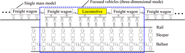
Fig. 1 Heavy-haul train-track coupled dynamic model
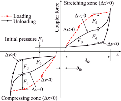
Fig. 2 Dynamic model of coupler and draft gear system
If the longitudinal relative displacement ��x between the adjacent vehicles is less than the coupler slack, the coupler longitudinal force Fc is
Fc=0 (1)
If the relative displacement varies between the coupler free slack and the maximum compression amount of the draft gear, then the coupler force depends on both the inter-vehicle relative displacement ��x and speed ��v. ��x>0 and ��x<0 respectively denote that the draft gear works in the stretching and compressing zones. For example, it will mainly work in the stretching state with ��x>0 when the locomotive pulls wagons. In this case, if ��v>0, the coupler force will increase, changing along the dashed line. If ��v<0, the coupler force will decrease, varying along the solid line as the arrow points. If ��v=0, the force changes according to the trend of the quasi-static force (F0). As for ��x<0 of the compressive zone, it has the similar working principle. To reduce the numerical oscillation induced by the abrupt change of ��v between the positive and negative, the switching speed vf is introduced, which can be viewed as an intermediate interval between ��v<0 and ��v<0. Then the coupler force can be uniformly expressed as
 (2)
(2)
If the relative displacement is larger than the maximum deformation, then
 (3)
(3)
where ��v denotes the inter-vehicle relative velocity, Fbuf is the reacting force of draft gear in its maximum stroke, Ks represents the structural stiffness of vehicle chassis.
3.2 Coupler lateral force
The coupler lateral force is closely related to the coupler lateral swing angle. It is assumed that the couplers between two adjacent vehicles are connected together as a rigid-straight bar without relative rotation. The coupler swing angle relative to the car body is defined as positive when it rotates around the draft key clockwise in the top view, otherwise it is negative.
In the straight line, the coupler swing angle is mainly affected by the relative displacements of the adjacent two vehicles, as shown in Fig. 3. If the vehicles run along the track center line straightly, the included angle between the car body center line and the line connecting the coupler yoke keys is zero. Once the car body has the spatial motions in other directions, the lateral displacements of draft keys in the front and rear vehicles can be calculated as
 (4)
(4)
where yci, fci and ��ci represent the lateral displacement, rolling angle and yaw angle of the ith car body, respectively; hcgi and lcgi denote the vertical distance between the coupler and the mass center of ith car body, respectively; for the front and rear vehicles, i=1, 2 in sequence.
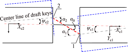
Fig. 3 Coupler swing angle in straight line
The included angle for the coupler relative to its centering position is
 (5)
(5)
where L1 and L2 represent the lengths of front and rear couplers, respectively.
The coupler swing angles ��1 and ��2 can be expressed as


 (6)
(6)
In practice, the amplitude of coupler swing angle is limited by the structures of the coupler and draft gear system. Once the coupler sways beyond the free swing limit, a restoring torque (M) will generate against its swing motion. Taking a pair of couplers as the analysis object, the coupler lateral force acting on the draft keys 1 and 2 in Fig. 3 can be calculated as
 (7)
(7)
where M1 and M2 are the restoring torques acting on the front and rear couplers.
3.3 Coupler vertical force
For the non-rigid couplers, the connected coupler heads permit their vertical relative motions. Therefore, the maximum force transferred is the maximum static friction force. The mechanical model of coupler vertical force is given in Fig. 4, where the coupler body is regarded as a rigid bar fixed on its corresponding car body. The relative research indicates that the coupler inertia has little influence on coupler force [22], so the vibrations of coupler itself are neglected. The vehicle system motions are the main factors affecting the coupler vertical force.
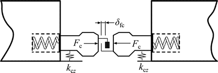
Fig. 4 Mechanical model of coupler vertical force
If the coupler longitudinal relative displacement is less than the coupler free slack, then Fcz=0. Otherwise, the calculation is discussed in two conditions.
1) If  , then
 (8)
(8)
2) If  then
then
 (9)
(9)
where ��z is the vertical relative displacement between the connected coupler heads, kcz is the vertical equivalent stiffness of coupler, vr is the switching speed, and ��0 is the friction coefficients.
4 Submodel of railway vertical section
The vertical section can be simplified as the function of gradient i�� varying with the line length l. At the grade change point of the actual line, a vertical curve is usually inserted to connect the adjacent ramps, which may decrease the gradient varying rate. The geometric relations between the ramps and vertical curves are shown in Figure 5. According to Ref. [23], the length of the vertical curve is Lvc��2Lta, and its tangent length is Lta��Rvc����i/2000, where ��i is the the thousandth of the gradient difference between the adjacent ramps. Then, the vertical distance can be calculated as
 (10)
(10)
So, the gradient in the vertical curve can be expressed as
 (11)
(11)
For the convex and concave curves, the upper and under signs of �� are selected, respectively.
5 Dynamic behaviours of coupler and draft gear systems for combined train
5.1 Train formation and calculation conditions
In the coal dedicated lines of China, the heavy-haul unit train and combined train are the two main marshalling types usually applied at present. Their hauling weights are within the range from 1��104 t to 2��104 t. In this section, the 2��104 t train is regarded as the research objective with the marshalling mode of HXD+105��C80+HXD+105��C80+train tail device. The coupler DFC-E100 of locomotive HXD has a free swing angle of 3��. And the freight wagon C80 is assembled with the No. 16 coupler and MT-2 draft gear. And the emergency braking with the braking initial speed of 80 km/h is chosen as the research operating condition.
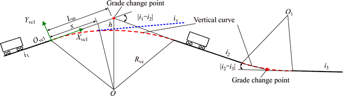
Fig. 5 Relations between ramps and vertical curves
The maximum gradients of the upline and downline of Daqin and Shuohuang railways are 4�� and 12�� respectively, and the maximum gradient difference reaches 8��. Based on the actual line data, six line conditions are set, including the straight line, the convex and concave vertical curves with the 8�� gradients difference, and three ramps with 4��, -4�� and -12�� gradients respectively. At the initial time, the grade change points of vertical curves are in the middle of train
5.2 Train longitudinal impulse in emergency braking condition
Based on the numerical model developed in section 2, the longitudinal dynamics for train emergency braking operation is analyzed firstly. In the calculations of pneumatic braking forces, the tested brake cylinder pressures of 2��104 t combined train in the emergency braking condition are used [24], as shown in Fig. 6. The brake cylinder pressures in different vehicles have different trends and the pressures in other vehicles are obtained by the interpolating calculation within the given curves. Then, the braking forces can be calculated easily.
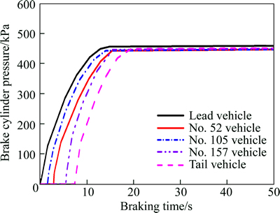
Fig. 6 Tested brake cylinder pressures of 2��104 t train in emergency braking condition
Figure 7 compares the coupler force distributions along the train length in different line conditions. It can be found that, in most lines, the maximum coupler tensile forces occur in the positions of 98-110th couplers, which distribute within the range of 904-1014 kN. For the coupler compression force, the peak values in the conditions of the straight line and single gradient ramps are 1523 kN, while that in the convex curve reduces to 924 kN. The largest compression force occurs in the concave curve, exceeding 2100 kN. It is also indicated that the simulated results for lines without vertical curve has little difference between each other, which means the gradient different has a more significant influence than the gradient. Besides, it needs to be explained that the similar emergency braking test has ever been carried out in a single ramp of Daqin railway line in July 2007. The tested compressive coupler force of the combined train is 1471 kN occurring in the middle vehicle (105th vehicle) [25], which agrees well with the calculated results.
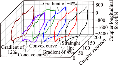
Fig. 7 Distributions of coupler longitudinal force along train length in different lines
5.3 Dynamic behaviors of coupler and draft gear system
5.3.1 Dynamic behaviors of couplers equipped in middle locomotives
Figure 8 shows the focused couplers closed to the middle locomotives, where F, B represent the front and back couplers in the vehicle, and the figures denote the coupler serial numbers.
Taking the concave curve condition as example, the coupler lateral forces of locomotives are displayed in Fig. 9. Once the train brakes in an emergency, the overall trends of couple forces present a distinct increase relative to the zero level, especially the forces acting on locomotives. The amplitude reaches 64 kN. For the couplers connecting wagons, the corresponding lateral force varies within a small range, and the maximum value does not exceed 25 kN. Therefore, the both ends of middle locomotives will bear the large and prolonged coupler lateral forces, which will threaten their running safeties doubtlessly.
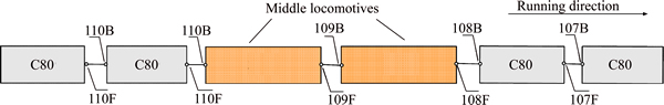
Fig. 8 Focused couplers for middle locomotives
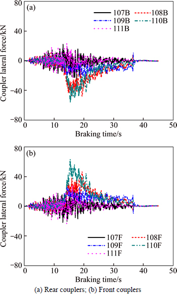
Fig. 9 Coupler lateral forces of train in concave section:
For the fourth locomotive, the relations between the coupler tilt states and train longitudinal impulse are analyzed deeply. Figure 10 reflects the influence of coupler longitudinal force on its lateral swing angles. In the different lines, the coupler compressive force increases gradually. Approximately within the 10 s of brake beginning, the couplers fluctuate nearby their centering positions. When the coupler compressive force increases to about 420 kN, the couplers have a fast unidirectional rotation and then stabilize, reaching the limit of free swing angle. As the train stretches with the sign of the coupler longitudinal force changing, the couplers return to their centering positions. What��s more, in the concave curve, the straight line and the convex curve, the duration time of coupler compressive state shortens in sequence, which leads to the corresponding holding time of coupler tilt state reduces orderly.
It should be pointed out that the coupler tilt direction has certain randomness actually. And the coupler tilt phenomenon is also related to its structural style. If the coupler is equipped with the coupler horn or coupler yoke key which provides the effective and large restoring force, it is difficult to tilt under the compressive force. Otherwise, the coupler will be relatively easy to tilt.
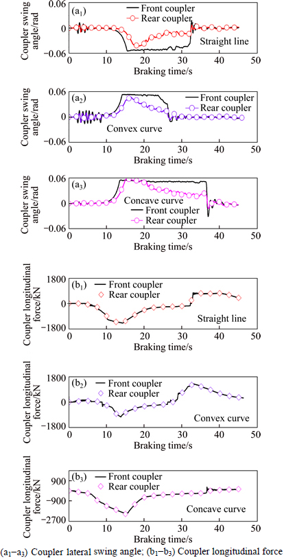
Fig. 10 Coupler swing angle and longitudinal force of the 4th locomotive in emergency braking case:
5.3.2 Dynamic behaviors of couplers equipped in freight wagons
While the couplers of middle locomotives tilt sideways, the dynamic behaviors of the connected wagon couplers will be affected. Figure 11 shows the coupler swing angles and coupler lateral forces of the wagon behind the 4th locomotive. Under the compressive force, the front coupler tilts obviously relative to its centering position, and the maximum tilt angle reaches 0.054 rad. The lateral component of the coupler force increases to 55 kN. In contrast, the rear coupler basically sways in the centering position. Its swing amplitude and coupler lateral force induced are below 0.01 rad and 25 kN, respectively.
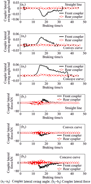
Fig. 11 Coupler swing angle and lateral force of the 106th freight wagon in emergency braking case:
In the 2��104 t train, another freight wagon which should be focused is the wagon subjected to the maximum coupler force. The changing relationships between the maximum coupler force and the swing angles of its rear couplers are given in Fig. 12. No matter how the coupler longitudinal force changes, the couplersstill oscillate near their original centering positions.
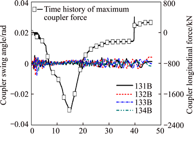
Fig. 12 Rear coupler swing angle of the 130th freight wagon in emergency braking case
In the 2��104 t combined train, the coupler tilt phenomena of the middle locomotives mainly affect the behaviors of the connected wagon couplers, while the couplers in other positions are influenced slightly. The reason is that the coupler stabilizing ability of wagon is stronger than that of the locomotive.
6 Dynamic characteristics of heavy-haul train in emergency braking
6.1 Dynamic performance of middle locomotive
When the train applies the emergency braking in the straight line, convex and concave curves, the wheelset lateral forces of the fourth locomotive are compared in Fig. 13. In different lines, the locomotive couplers tilt without exception, which leads to the local sudden changes of the wheel-rail forces within the time interval of 15-20 s. The wheelset lateral forces reach the maximum.
The general variant trends of the wheelset lateral forces are related to the tilt directions of locomotive couplers.
1) In the convex and concave curves, the coupler tilt directions are shown in Fig. 14(a). From the view of the force equilibrium, the coupler forces (Fc1, Fc2) acting on the two ends of locomotive produce a clockwise moment. Each wheelset needs an opposite force to balance the locomotive to a new equilibrium state. Thereby, the additional wheelset lateral forces like Fy1 and Fy4 will occur. Simultaneously, the coupler forces are transferred to wheelsets, and then the induced wheelset rolling motion around the X axis causes the wheel load transfer.
2) In the straight line, the coupler tilt directions are opposite, as shown in Fig. 14(b). The coupler forces (Fc1, Fc2) acting on the locomotive produce an anticlockwise moment, which makes the additional wheelset lateral forces  and
and  occur.
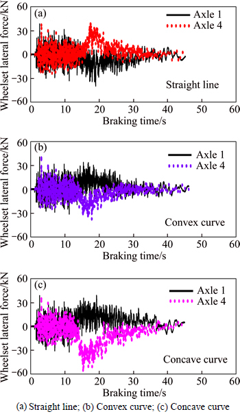
Fig. 13 Wheelset lateral forces of the 4th locomotive:

Fig. 14 Coupler forces acting on the 4th locomotive and inducing additional forces:
6.2 Dynamic performance of freight wagons in different positions
For the freight wagons, the 106th and 130th ones are selected to be analyzed, which respectively locate behind the 4th locomotive and near the maximum coupler force. Figure 15 indicates the couplerlongitudinal forces and the coupler tilt angles of the 106th wagon. In the convex vertical curve and concave curve, the front coupler swing angle �� induces the additional wheelset lateral force Fy1, while the rear coupler basically stays around the centering position. And in the straight line, the front coupler force results in an extra wheelset lateral force with the opposite direction (see Fig. 15(b)). It is noteworthy that the tilt angle peak value of wagon front coupler reaches 0.054 rad (about 3.1��), which is equal to maximum free swing angle of locomotive coupler but far below that of No. 16 coupler.
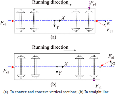
Fig. 15 Coupler forces acting on the 106th wagon:
For the 106th and 130th freight wagons, the variations of wheel-rail forces in the emergency braking are compared in Fig. 16. Within the time interval of 15-20 s, the wheelset lateral forces of axle 1 in the 106th wagon wholly increase. As for the axle 4, the lateral forces fluctuate around the average value, and their variation trends almost have no change. The coupler stabilizing ability in the wagon is very strong. The tilt of wagon coupler is mainly affected by the locomotive couplers.
6.3 Comparisons of wheel-rail dynamic indices of locomotive and freight wagon
Four wheelsets in the middle locomotives and wagons are selected as the comparing objects (see Fig. 17). A and B represent the 1st and 4th wheelsets of 4th locomotive, C and D denote the 1st wheelsets of the 106th and 130th wagons respectively. All the vehicles have the same property, bearing the large compressive coupler force in the emergency braking.
Taking the wheelset lateral force, wheel-rail vertical force, derailment coefficient and wheel load reducing rate as the studied dynamic indices, Fig. 18 shows the maximum values of each index in different vehicles. Generally, the wheel-rail lateral interaction of vehicles are affected more significantly by the train longitudinal impulse, especially that of the middle locomotive. For the three line conditions, the average values of the lateral forces in wheelset A and B reach 43.6 kN and 38.7 kN successively, while that in wheelsets B and C are 27.5 kN and 11 kN in sequence. By comparisons, the maximum difference between the force magnitudes is greater than 30 kN, which means that the wheel-rail lateral interactions of the locomotive are much more violent than the 106th and 133th wagons. Viewed from the vertical forces of wheelsets A, B, C and D, their corresponding average values in three line conditions are 157.7 kN, 161.5 kN, 143.7 kN and 142.6 kN, with the difference below 20kN between each other.
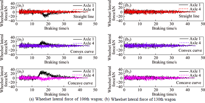
Fig. 16 Comparisons of wheel-rail forces for freight wagons in different positions:
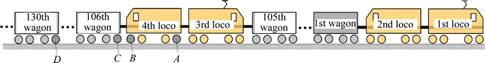
Fig. 17 Target wheelsets of 2��104 t combined train
As for the derailment coefficients of wheelsets A, B, C and D, the average magnitudes in different lines are 0.25, 0.26, 0.22 and 0.18. Though the maximum difference between each other is 0.07, the difference percentage has approached 30%. Similarly, the max difference of wheel load reduction rates for the studied wheelsets is less than 0.05, but its corresponding percentage is closed to 24%.
In general, for the 2��104 t power-distributed train applying the emergency braking in different vertical sections, the wheel-rail dynamic performance of middle locomotive is most violent, followed by its neighboring freight wagon. For the wagons disconnecting to the locomotives, the longitudinal impulse has the weakest influence on their running safeties, even if they bear the maximum coupler forces.
7 Conclusions
1) When the 2��104 t train brakes urgently in the different vertical sections, the coupler and draft gear systems are compressed predominately. The violent longitudinal impulse occurs with the maximum coupler longitudinal forces in the concave curve section.
2) When two coupled locomotives are arranged in the middle position of the train, the middle couplers of the locomotives will easily tilt to the limit value of the coupler free swing angle under the coupler compressive forces. This causes the same phenomena of the connected wagon couplers. However, the wagon couplers disconnecting with the middle locomotives basically keep in the centering position, even though they bear the larger coupler forces. It can be attributed to the stronger stabilizing abilities of the wagon coupler. Affected by the tilt of the middle coupler, the wheel-rail lateral interactions of the middle locomotives are intensified obviously, becoming the most dangerous part in the combined train. Meanwhile, the dynamic performance of the connecting wagon also deteriorates obviously, while that of the wagon disconnecting with the middle locomotives has little change.
3) Compared with the wheel-rail vertical interaction, the lateral interaction is affected more significantly by the train longitudinal impulse. In the actual operation of the combined train, the running safeties of the middle locomotives should be pay be much more attention once the braking control is applied.
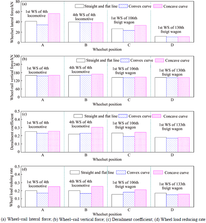
Fig. 18 Influence of line conditions on wheel-rail dynamic indices of vehicles in different positions:
References
[1] WANG Juan. Influence of coupler draft gears on the safety of heavy haul train under longitudinal stress [D]. Chengdu: Southwest Jiaotong University, 2009. (in Chinese)
[2] CHENG Hai-tao, FANG Ke-juan. Dynamic simulation for working conditions in braking and uniform running of freight cars [J]. Rolling Stock, 1999, 37(11): 9-11. (in Chinese)
[3] ENGLISH G W, MOYNIHAN T W. Causes of accidents and mitigation strategies [R]. Kingston Ontario: TranSys Research Ltd, 2007.
[4] WILSON N, FRIES R, WITTE M. Assessment of safety against derailment using simulations and vehicle acceptance tests: A worldwide comparison of state-of-the-art assessment methods [J]. Vehicle System Dynamics, 2011, 49(7): 1113-1157.
[5] COLE C. Improvements to wagon connection modelling for longitudinal train simulation [C]// Proceedings of Conference on Railway Engineering. Rockhampton: Institution of Engineering, 1998: 187-194.
[6] COLE C, MCCLANACHAN M, SPIRYAGIN M, SUN Y Q. Wagon instability in long trains [J]. Vehicle System Dynamics, 2012, 50(Suppl.): 303-317.
[7] CHOU M, XIA X, KAYSER C. Modelling and model validatioin of heavy-haul trains equipped with electronically controlled pneumatic brake systems [J]. Control Engineering Practice, 2007, 15: 501-509.
[8] NASR A, MOHAMMADI S. The effects of train brake delay time on in-train forces [J]. Proceedings of the Institution of Mechanical Engineers, Part F: Journal of Rail and Rapid Transit, 2010, 224: 523-534.
[9] QI Zhao-hui, HUANG Zhi-hao, KONG Xian-chao. Simulation of longitudinal dynamics of long freight trains in positioning operations [J]. Vehicle System Dynamics, 2012, 50(9): 1409-1433.
[10] AFSHARI A, SPECCHIA S, SHABANA A A. A train air brake force model: Car control unit and numerical results [J]. Proceedings of the Institution of Mechanical Engineers, PartF: Journal of Rail Rapid Transit 2012, 227(1): 38-55.
[11] CHEN D. Derailment risk due to coupler jack-knifing under longitudinal buff force [J]. Proceedings of the Institution of Mechanical Engineers, Part F: Journal of Rail and Rapid Transit, 2010, 224: 483-490.
[12] PUGI L, RINDI A, ERCOLE A G. Preliminary studies concerning the application of different braking arrangements on Italian freight trains [J]. Vehicle System Dynamics, 2011, 49(8): 1339-1365.
[13] ZHANG Z Y, DHANASEKAR M. Dynamics of railway wagons subjected to braking torques on defective tracks [J]. Vehicle System Dynamics, 2012, 50(1): 109-131.
[14] YANG Liang-liang, KANG Yu, LUO Shi-hui. Assessment of the curving performance of heavy haul trains under braking conditions [J]. Journal of Modern Transport, 2015, 23(3): 169-175.
[15] ALLOTA B, CONTI R, MELI E. A. Railway vehicle dynamics under degraded adhesion conditions: An innovative HIL architecture for braking test on full-scale roller-rigs [J]. International Journal of Railway Technology, 2014, 2(3): 21-53.
[16] WEI Lei, ZENG Jing, WANG Qun-sheng. Investigation of in-train stability and safety assessment for railway vehicles during braking [J]. Journal of Mechanical Science and Technology, 2016,30(4): 1507-1525
[17] ZHAI Wan-ming. Vehicle-track coupled dynamics [M]. 4th Edtion, Beijing: Science Press, 2015. (in Chinese)
[18] ZHAI Wan-ming, GAO Jian-ming, LIU Peng-fei. Reducing rail side wear on heavy-haul railway curves based on wheel�Crail dynamic interaction [J]. Vehicle System Dynamics, 2014, 52(Suppl.): 440-454.
[19] LIU Peng-fei, ZHAI Wan-ming, WANG Kai-yun. Establishment and verification of three-dimensional dynamic model for heavy-haul train track coupled system [J]. Vehicle System Dynamics, 2016, 54(11): 1511-1537.
[20] LIU Peng-fei, WANG Kai-yun, ZHAI Wan-ming. Dynamics Interaction between heavy-haul locomotive and track under driving conditions [J]. Journal of Southwest Jiaotong University, 2014, 49(1): 15-20. (in Chinese)
[21] WANG Fu-tian. Vehicle system dynamics [M]. Beijing: China Railway Publishing House, 1994. (in Chinese)
[22] MASSA A, STRONATI L, ABOUBAKR A K. Numerical study of the non-inertial systems: application to train coupler systems [J]. Nonlinear Dynamics, 2012, 68: 215-233.
[23] YI Si-rong. Railway engineering [M]. 2nd Edition. Beijing: China Railway Publishing House, 2009. (in Chinese)
[24] Locomotive & Car Research Institute. Experimental research of 20000 t heavy-haul train in Daqin railway line [R]. Beijing: China Academy of Railway Sciences, 2007. (in Chinese)
[25] TAO Qiang, YAO Xiao-pei, WU Pei-yuan, SUN De-huan. Comparative analysis of coupler longitudinal forces for 20000t heavy-haul combined train in braking test of Daqin railway line [C]// Proceedings of 12th Vehicle Brake Sympsium of China Railway Society. Wuxi: China Railway Society, 2009: 40-62.
(Edited by DENG L��-xiang)
Cite this article as:
LIU Peng-fei, WANG Kai-yun. Dynamic performance of heavy-haul combined train applying emergency braking on straight line [J]. Journal of Central South University, 2017, 24(8): 1898-1908.
DOI:https://dx.doi.org/https://doi.org/10.1007/s11771-017-3597-3Foundation item: Projects(51605315, 51478399) supported by the National Natural Science Foundation of China; Project(2013BAG20B00) supported by the National Key Technology R&D Program of China; Project(TPL1707) supported by the Open Project Program of the State Key Laboratory of Traction Power, China
Received date: 2015-11-30; Accepted date: 2017-01-16
Corresponding author: WANG Kai-yun, PhD; Tel: +86-28-87600773; E-mail: kywang@swjtu.edu.cn
Abstract: A heavy-haul train-track coupled model is developed. Taking the emergency braking of the 2��104 t combined train as example, the train longitudinal impulse, the coupler dynamic behaviors and wheel-rail interactions of vehicles distributing in the different positions are analyzed. The results indicate that under the coupler compressing forces, the couplers of middle locomotives may tilt to the free swing limits, which induces the unidirectional tilt of their connected wagon couplers. Consequently, the coupler longitudinal forces produce the lateral components, and then affect the wheel-rail dynamic interaction. The performance of the middle locomotive and their neighboring freight wagons deteriorate significantly, becoming the most dangerous parts in the combined train. The wagons disconnecting with the locomotives can basically keep their couplers to stabilize in the centering positions, even though the maximum coupler longitudinal force acts on it. And its corresponding running safety also has little changes.
