
Trans. Nonferrous Met. Soc. China 30(2020) 3124-3232
Transport phenomena in meniscus region of horizontal single belt casting
Mian-guang XU1, Roderick GUTHRIE2, Mihaiela ISAC2
1. School of Mechanical Engineering, Shandong University of Technology, Zibo 255000, China;
2. McGill Metals Processing Center, McGill University, 3610 University Street, Montreal, QC H3A 2B2, Canada
Received 1 January 2020; accepted 25 September 2020
Abstract:
The horizontal single belt casting (HSBC) incorporating a single-impingement feeding system was simulated with an improved numerical model. Physical experiments were carried out on the pilot-scale caster for validation. The results show that the meniscus turbulence neither comes from the tundish region, nor from the impingement between the melt and the moving belt. It is the moving belt that gives rise to this high turbulence region, and this region can stir the melt near the meniscus. The feeding system studied and the moving belt give rise to a buffer region, which can optimize casting parameter variations, especially melt depth changes in the tundish. The temperature change rate of the bottom surface of the strip is around 4 times faster than that of the upper surface.
Key words:
horizontal single belt; transport phenomenon; strip casting; numerical simulation; meniscus;
1 Introduction
It is acknowledged that direct strip casting for metal sheets is theoretically more advantageous than conventional continuous casting (CCC) processes [1-3]. The idea of producing metallic sheets/strips directly from molten metal was first conceived by BESSEMER [4]. Since then, the near net shape casting (NNSC) concept has attracted many researchers. Many NNSC processes have been proposed, and many advances have been made, especially in the field of non-ferrous metals. The majority of strip casters are composed of either a single belt, a single roll, a belt with a roll, or twin belts, or twin rolls. These belts or rolls are used as the cooling substrate(s). Despite the evident physical differences in machine designs, the belt may be assumed as a type of roll, of infinite diameter, i.e. , with D being the roll diameter. Based on this concept, all existing strip casters can basically be classified into two categories: single cooling substrates or double cooling substrates, and the advantages and disadvantages of these two generic types of strip casters can be compared. A potential advantage for single-cooling-substrate processes is that it can avoid significant central porosity and macro- segregation problems. The microstructure of as-cast horizontal single belt casting (HSBC) AA6111 strip in Ref. [5] shows a uniform cast microstructure across the strip thickness, revealing small equiaxed grains for the bottom, middle, and top of an as-cast HSBC AA6111 strip.
HSBC for forming metal sheets via a NNSC method was first reported by researchers at McGill University [6], as well as at the University of Clausthal, more than twenty years ago [7]. More recently, the HSBC process for steel has been commercialized at Salzgitter��s Peine Plant, located in Germany, under the name ��belt cast technology��. With a 12 m-long water-cooled belt, it has the potential of 2 Mt/year output. Since this single belt process was first patented in 1990, extensive research, first carried out in Australia by Broken Hill Proprietary (BHP), and later in Canada, at the McGill Metals Processing Center (MMPC), revealed the effects of various feeding systems on the transport phenomena, microstructures, and mechanical properties of various aluminum and steel alloy systems [8]. The HSBC re-located to McGill, was used to produce thin strips of aluminum alloys being 250 mm in width and 5 mm in thickness. These included AA6111, as well as AA5182, and AA2024 alloys.
In the HSBC process, the heat flux always flows from the upper surface of the strip down towards the bottom, so central quality problems are eliminated. Uniform microstructure across the thickness of the strip is demonstrated in the experimental results [5]. More importantly, this type of heat flow gives rise to an asymmetric solidification process and perhaps counter- intuitively, leads to the roughly uniform microstructure across the thickness of the strip. Given that this process has now achieved commercial success in steel strip production in Germany [5], it can also be expected for aluminum sheet production. Promising results have been achieved at McGill through numerous tests and experiments for aluminum alloys such as AA6111. Although only a few studies have been conducted so far on other non-ferrous alloys using HSBC, experimental results strongly indicate that the HSBC process will achieve commercial success in the production of all sheet metals and help revolutionize the metal forming industries. The basic design is shown in Refs. [9,10].
In the present study, emphasis is placed on the region between the back meniscus in HSBC and 300 mm downstream. This is because within this region, the melt is distributed onto the moving belt, and acquires the same speed as the belt, but freezing has not commenced. The region involves strong momentum and energy interchanges between the liquid metal and the moving belt. The single-impingement feeding system previously employed by the MMPC was re-analyzed for heat transfer phenomena using more realistic models and boundary conditions. Thus, the present mathematical model uses a low Reynolds turbulence model [11]. To improve precision, both the roughness model and the non-iterative time advancement solution method introduced in previous studies [9,10], were avoided. New phenomena were observed from the numerical results, which seem to be worthwhile reporting, as they may serve as a starting point for future development work. From these results, the single-impingement feeding system can be used to provide controllable driving forces induced from the motion of the single belt, which can be modified by optimizing the feeding system geometry. It is hoped that this will eliminate negative influences to strip quality and strip profiles caused by variations in casting parameters. Experiments previously carried out using the pilot-scale caster were used to partly validate these numerical results.
2 Numerical models
The numerical models presented in the present study are based on previous studies [9,10], and include further developments. Differing from previous publications [9,10], in this work, a low Reynolds number turbulence model proposed by LAM and BREMHORST [11] was adopted to examine the fluid flow because in the HSBC process, the solidified shell only forms in a very narrow region just against the cooling substrate. The turbulence model employed in the present work does not have to be used in conjunction with the empirical wall function formulas and will remain valid throughout the entire simulation domain. It provides more accurate predictions with higher but acceptable computational cost. Additional Darcy source terms [12] were added to the model, so as to account for fluid flows passing through the mushy region during the solidification process. The mushy zone parameter was calculated based on the secondary dendrite arm spacing (SDAS), obtained from the experiments. For AA6111, an average of 20 ��m for SDAS was adopted in this work. The mushy zone parameter obtained is 6.8��108 according to Refs. [12-14]. Details regarding the mass equation, momentum equations, and the volume of fluid (VOF) equation have been described in detail in previous publications [9,10]. The roughness model [9,10] was not employed for this model, as it only works when solidification is not considered. When there exists a solidified shell, the roughness model will reduce the near wall flow and leads to an inaccurate flow field prediction. The mathematical model performed was solved using the commercial software ANSYS FLUENT 14.5, which is based on the finite volume method (FVM).
The coordinate and structured grid mesh systems are shown in Fig. 1. When the full length of the moving belt is 2.6 m, the present modeling domain will be restricted to only a short length downstream of the back meniscus point. This region corresponds to the fully molten length of a simulation domain, and has been discussed in our previous publication [15]. Given that the belt has longitudinal symmetry, only half of the belt region was simulated, so as to reduce computational costs. During experiments, only part of the steel belt was covered by the melt strip and the region of interest focuses on the area from the back meniscus point to 300 mm downstream. The metal did not lose heat on the refractory wall (i.e. adiabatic). The boundary condition for the moving belt can then be described by
q=h(T-Tamb) (1)
where q is the heat flux, h is the heat transfer coefficient (5 kW/(m2��K) [9,10]), T is the temperature of the bottom surface of the strip, and Tamb is the temperature of the upper surface of the moving belt, which is set to be 25 ��C.
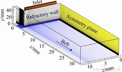
Fig. 1 Coordinate and structured mesh grid systems of three-dimensional simulation domain
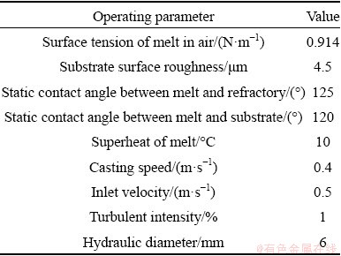
With regards to the accuracy and mesh grid independence, 6.5��105 structured cells were used over the entire simulation domain. The inlet velocity for the mixture, that is normal to the inlet boundary, was fixed to be 0.5 m/s. Moreover, the volume fraction of the liquid metal phase at the inlet was fixed to be 100%. The moving speed of the horizontal belt was set to be 0.4 m/s, smaller than that of the inlet (Fig. 1), so as to obtain the desired strip thickness. The initial solution for the governing equations was to assume that the temperature throughout the entire simulation domain was ambient temperature (25 ��C), whilst velocities, turbulence quantities, and melt fractions were set to be zero. The convergence criterion for all simulations was set such that all residuals reached 10-4 for all equations. To improve the accuracy, all equations were discretized with a second-order upwind scheme over the entire simulation domain. The iterative time advancement method [16] was used to improve the accuracy. Other simulation details and related parameters can be found from previous publications [9,10,16]. In terms of the material, the chemical composition of AA6111 aluminum alloy can be found in Table 1. Other parameters can be found in Tables 2 and 3.
Table 1 Chemical composition of AA6111 aluminum alloy (wt.%)
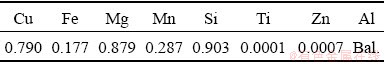
Table 2 Physical properties of fluids
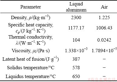
Table 3 Operating parameters used in models
3 Results and discussion
3.1 Meniscus turbulence
Figure 2 illustrates the predicted turbulence kinetic energy, that is, the mean kinetic energy associated with eddies in the turbulent flow. This can be used to describe the turbulence level in the region. From Fig. 2, for a single-impingement feeding system, the turbulence arising from the meniscus gap region neither comes from the tundish region nor from the impingement between the melt jet and the horizontal moving belt. In fact, the energy maintaining this high-level turbulence is generated by the horizontal moving belt. The same conclusion was drawn for an inclined feeding system (two impingements) shown in the previous publication [17]. This kind of turbulence energy can be transferred downstream as the casting process continues.
However, Fig. 2(c) shows that this high kinetic energy of turbulence gradually disperses downstream, up to roughly 20 mm downstream of the gap. During its dispersion, the turbulence arising from the gap region can stir the impingement region and give rise to a stir zone (high turbulence region), as shown in Figs. 2(b) and (c). Also, once the strip moves out of the region formed by the refractory wall and the belt, the moving, upper surface of the melt can also stir the air region and form another stir zone. In general, strong turbulence gives rise to high heat transfer rate. As such, heat release near the high turbulence region will be very fast. It is beneficial to having a fast release of the superheat, which thereby gives rise to a full mushy state region. This fast release of the superheat gives rise to a peak heat flux. The peak heat flux was demonstrated in our previous experiments carried out in the pilot-scale caster [8].
As described in Fig. 2, turbulence on the moving belt arises from the meniscus region, whilst the turbulence kinetic energy near the belt decreases faster. Figure 3 shows the predicted turbulence kinetic energy at the plane z=50 mm and t=1.515 s. where 15 mm downstream the meniscus, turbulence on the strip��s bottom surface starts to diminish. By 125 mm away from the meniscus, the kinetic energy of turbulence in the strip totally disappears. This indicates that the length of the hydraulic jump region is around 120 mm. The decrease in turbulence can be attributed to (1) natural turbulence dissipation induced by viscosity and (2) the solidification process itself, giving rise to a mushy state region, in which the thickness of this region increases with increasing distance downstream. The solidification process will be discussed in the following passage. From Figs. 2 and 3, we can understand that the turbulence of the strip starts in the meniscus region due to the motion of the belt.
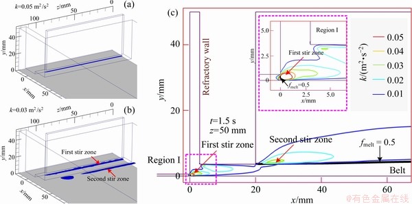
Fig. 2 Predicted iso-surfaces of turbulence kinetic energy (k) at t=1.515 s (a, b) and predicted turbulence kinetic energy distribution at plane z=50 mm (c) (fmelt is melt volume fraction)
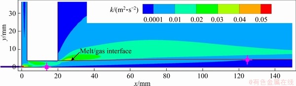
Fig. 3 Predicted turbulence kinetic energy at plane z=50 mm and t=1.515 s
3.2 Entrapped air pockets
Figure 4 illustrates the entrapped air pockets near the meniscus region. Aside from the high heat dissipation rate, the high surface turbulence may cause gas entrapment. As a moving mould technology, the starting point of the meniscus region is being continuously disturbed by the motion of the belt. The same phenomenon was found with the inclined feeding system discussed in the previous publication [17]. The previous model was based on the volume of fluid (VOF) model [11,12] and showed that there exists a high frequency behavior (~102 Hz level) [15]. The predictions are, however, different from those obtained from Eulerian-Eulerian model, which predicts a very thin air film between the strip and the moving belt [18]. Regardless of which model was employed, the entrapped air pockets found in the VOF [15] and the thin air film found with the Eulerian-Eulerian model [18] indicate that there exists a high heat transfer resistance between the strip and belt. This will delay the solidification process. One thing to note is that the liquid Al-base alloys are very reactive to the atmosphere and that it is reasonable to assume that the surface layer is always relatively rapidly oxidized. This may be an advantage since the oxide layer can prevent gas from penetrating into the body of the strip.
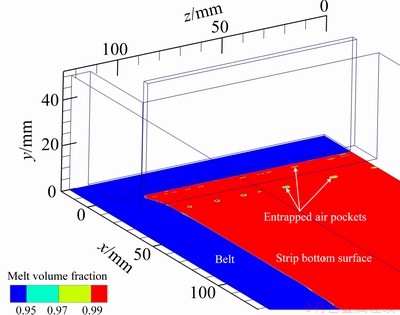
Fig. 4 Predicted meniscus entrapped air pockets dragged into melt/air interface from meniscus
In Fig. 4, further down the stream, the predicted entrapped air pockets disappear. This could be due to the numerical error, but could also be a reflection of the real practice in which the hydrostatic forces cause these gas pockets to flatten out. However, from these simulated results, it may be concluded that the entrapped air pockets cannot be completely avoided. There is no doubt that once the melt touches against the belt, air entrapment can occur. Fortunately, the air phase cannot penetrate the surface of the strip due to the oxide film and will not cause any internal quality problem. However, shrinkage during solidification can modify these entrapped air pockets, which might increase the size of the entrapped air pockets. A possible way to decrease the air entrapment phenomenon is to delay the solidification process as far as possible, so as to cause these entrapped air pockets to deform again, and flatten them before the solidified shells form. This deformation process for the entrapped air bubbles can be termed ��self-healing��, which may determine the success for any strip casting processes. In a successful strip casting process for aluminum and its alloys, additional forces, such as rolling forces, exerted on the mushy state metal, could also play a vital role.
3.3 Velocity distribution
Figure 5 indicates the predicted velocity field on the xy planes (at z=50 mm) and predicted longitudinal velocities along line on planes y= 0.25 mm and z=50 mm. In Fig. 5(a), with the current single-impingement feeding system, the meniscus is formed by the inactive near-wall flow of the feeding system, similar to that for an inclined feeding system. In Fig. 5(b) there exists an over-speed region (velocity > belt speed), whose component along the x direction exceeds 0.7 m/s, which is 50% faster than that of the belt motion (0.4 m/s). Fortunately, the turbulence level in this over-speed region is lower than that in the meniscus region, and is largely determined by the geometry of the feeding system. Figure 5(c) shows the predicted velocities along the line on planes y=0.25 mm and z=50 mm. In this image, at the meniscus, there exist very active flows, although these flows are supplied by inactive near-wall flows shown in Figs. 5(a) and (b). These active flows are accompanied by high turbulence levels as indicated in Fig. 3. The velocity component along the y direction (gravity direction) is induced by the renewal of the meniscus, instead of the impingement of the incoming melt stream. This indicates that the turbulence at the meniscus neither comes from the launder/tundish region, nor from the delivery process between the tundish and the belt. For the current single-impingent feeding system, this delivery process is realized by an enclosed rectangular vessel. For the previous inclined feeding system (multi-impingement feeding system), the delivery process is realized by an inclined, half open, refractory wall. This inclined wall can offer a resistive force to decrease the melt speed due to its rough surface.
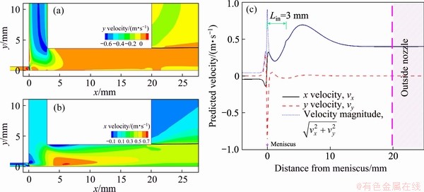
Fig. 5 Predicted vertical (a) and horizontal (b) velocity fields and predicted x and y velocities along line on planes y=0.25 mm and z=50 mm (c)
The melt depth in the delivery tundish (or launder) versus the fluid velocity through the slot nozzle have been studied by water modeling experiments [19,20]. A suitable melt depth hmelt can be predicted by the experimental data. However, in real practice, it is difficult to avoid depth variations in the delivery tundish (or launder). These variations could give rise to thickness variations in the cast strips. In our previous work, ��pressure- driven�� flows have been proposed [15]. In the present work, due to that, for the single- impingement feeding system, the enclosed vessel is used to deliver the melt from the tundish to the moving belt, and is capable of offering the possibility of ��pressure-driven�� flows, as shown in Fig. 6. At the start of casting, the melt is driven by the static pressure in the tundish region. This static pressure can be modified according to the width of the slot, and by flow conditions. To obtain the desired melt velocity, several empirical formulae can be used. In steady state casting, the vessel is filled with metal. During this state, the volume rate through the slot nozzle is not simply determined by the melt depth in the tundish region. This volume rate is largely determined by the belt speed. The decrease of the melt depth in the tundish region would not decrease the volumetric flow rate, because at this time, a ��negative pressure region�� could form and drive the melt flow, rather than by gravity driven flow. The increase in melt depth in the launder region can give rise to a ��positive pressure region��. The potential of ��pressure-driven�� is very good for the strip quality, simply because the melt depth variation cannot be avoided. With the inclined feeding system (multi-impingement), the instabilities of the pressure can give rise to non- uniform flows, thus causing the thickness variations of the strip. But for the single-impingement feeding system in this work, these instabilities induced in the tundish region can be easily avoided, indicating that the casting process could be more stable.
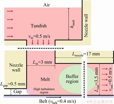
Fig. 6 Buffer region of delivery system between refractory wall and moving belt
3.4 Solidification and strip profile
The predicted temperature distributions on strip surfaces are shown in Fig. 7, which indicates that the bottom surface temperature is less than the upper surface temperature. This result is reasonable as the bottom surface is always in contact with the water-cooling substrate and its cooling rate is higher. In this image, it can also be seen that the temperature at the edge of the strip decreases faster. In addition, at 0-80 mm away from the meniscus, the upper surface temperature is variable, which is probably induced by the surface turbulence. However, at 300 mm away from the meniscus, the temperature at the bottom surface decreases by approximately 70 ��C, while the temperature of the upper surface decreases by approximately 15 ��C. This implies that the cooling rate of the bottom surface is about 4 times greater than that of the upper surface for the aluminum alloy at a casting speed of 0.4 m/s. In the present simulation, the superheat is 10 ��C, which implies that the superheat would be completely released at 300 mm away from the meniscus with the current boundary conditions.
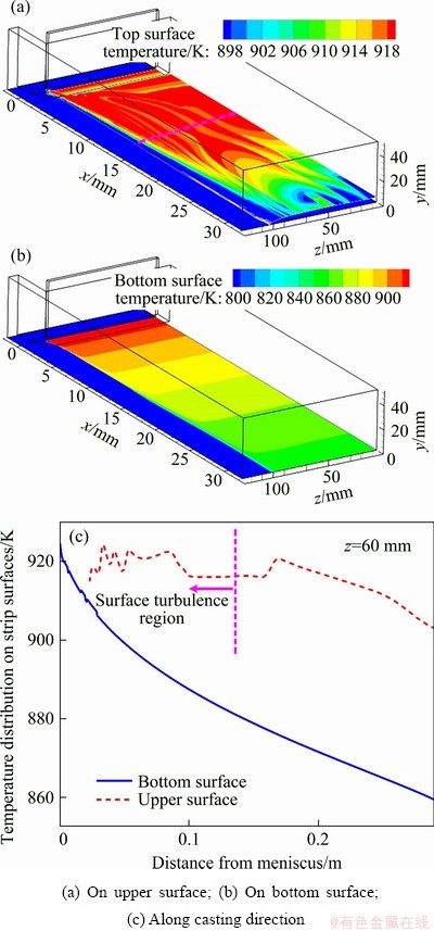
Fig. 7 Predicted temperature distributions on strip surfaces
Figure 8 illustrates the strip profile obtained by the simulation and experiments. The predicted strip profile is thin near the edge and this is consistent with results from experiments. From Fig. 8, it can be seen that near the edge, the width becomes narrower as the surface tension force is larger at the edge. Both the surface tension and the pressure can be used to prevent the leakage of the melt and maintain the strip profile, and provide a round edge profile without using a dam, for a 5 mm-thick strip. Moreover, with the controllable negative pressure shown in Fig. 6, the melt depth variations in the tundish region would no longer influence strip thickness.
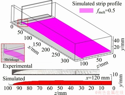
Fig. 8 Strip profiles showing simulated and experimental samples
4 Conclusions
(1) The meniscus turbulence neither comes from the launder/tundish region, nor from the impingement between the melt and the horizontal moving belt. It is the moving belt that gives rise to this high turbulence region, and this region can stir the melt near the meniscus. The moving strip can also stir the gas to form another high turbulence zone in the upper gas phase.
(2) The single-impingement feeding system used in the present study can give rise to a buffer region between the refractory wall and the belt. This effect is induced by the belt movement and can be used as a buffer zone to optimize casting parameter variations, especially any melt depth changes in the tundish.
(3) The temperature near the strip��s edge decreases faster. The temperature of the bottom surface of the strip decreases around 4 times faster than that of the upper surface.
Acknowledgments
The authors would like to acknowledge the financial support received from the research grant of Shandong University of Technology (4041/419099), the Natural Sciences and Engineering Research Council of Canada (NSERC), from the International Advisory Board of Supporting Companies of the McGill Metals Processing Centre (MMPC). The authors would also like to acknowledge the support in software licensing received from ANSYS Inc. to facilitate this research.
References
[1] SHIBUYA K, OZAWA M. Strip casting techniques for steel [J]. ISIJ International, 1991, 31: 661-668.
[2] ZAPUSKALOV N. Comparison of continuous strip casting with conventional technology [J]. ISIJ International, 2003, 43: 1115-1127.
[3] MALEKI A, TAHERIZADEH A, HOSSEINI N. Twin-roll casting of steels: An overview [J]. ISIJ International, 2017, 57: 1-14.
[4] BESSEMER H. On manufacture of continuous sheets of malleable iron and steel direct from fluid metal [J]. Journal of Metals, 1965, 17: 1189-1191.
[5] GUTHRIE R I L, ISAC M. Conventional and near net shape casting options for steel sheet [J]. Ironmaking Steelmaking, 2016, 43: 650-658.
[6] GUTHRIE R I L, HERBERTSON J G. Continuous casting of thin metal strip: U.S. Patent, 4928748 [P]. 1990-05-29.
[7] SCHWERDTFEGER K, SPITZER K, KROOS K, FUNKE J, FUNKE P, HOWER K. Further results from strip casting with the single-belt process [J]. ISIJ International, 2000, 40: 756-764.
[8] GUTHRIE R I L, ISAC M. Horizontal single belt casting of aluminum and steel [J]. Steel Research International, 2014, 85: 1291-1302.
[9] GE S, CLIKIN M, ISAC M, GUTHRIE R I L. Mathematical modeling and microstructure analysis of Al-Mg-Sc-Zr alloy strips produced by horizontal single belt casting (HSBC) [J]. ISIJ International, 2014, 54: 294-303.
[10] GE S, CLIKIN M, ISAC M, GUTHRIE R I L. Analysis and evaluation of novel Al-Mg-Sc-Zr aerospace alloy strip produced using the horizontal single belt casting (HSBC) process [J]. Metallurgical and Materials Transactions B, 2015, 46: 1035-1043.
[11] LAM C K G, BREMHORST K. A modified form of the k-�� model for predicting wall turbulence [J]. Transactions of the ASME, 1981, 103: 456-460.
[12] VAKHRUSHEV A, WU M H, LUDWIG A, TANT Y, HACKL G, NITZL G. Numerical simulation of shell formation in thin slab casting of funnel-type mold [J]. Metallurgical and Materials Transactions B, 2014, 45: 1024-1037.
[13] LI Xiang-long, LI Bao-kuan, NIU Ran, HUANG Xue-chi. Large eddy simulation of electromagnetic three-phase flow in a round bloom considering solidified shell [J]. Steel Research International, 2019, 90: 1-13.
[14] LI Xiang-long, LI Bao-kuan, LIU Zhong-qiu, NIU Ran, LIU Qiang. In-situ analysis and numerical study of inclusion distribution in a vertical-bending caster [J]. ISIJ International, 2018, 58: 2052-2061.
[15] XU M G, ISAC M, GUTHRIE R I L. A numerical simulation of transport phenomena during the horizontal single belt casting process using an inclined feeding system [J]. Metallurgical and Materials Transactions B, 2018, 49: 1003-1013.
[16] ANSYS Inc. FLUENT 14.5-Manual [Z]. ANSYS Inc. Lebanon, NH, USA, 2012.
[17] XU M G, ISAC M, GUTHRIE R I L. Transport phenomena during horizontal single belt casting process using an optimized inclined feeding system [J]. Ironmaking Steelmaking, 2018, 45: 878-885.
[18] XU M G, ISAC M, GUTHRIE R I L. Flow instabilities in the horizontal single belt casting process with an inclined feeding system [J]. ISIJ International, 2019, 59: 69-75.
[19] TRUELOVE J S, GRAY T A, CAMPBELL P C. Fluid dynamics, heat transfer and solidification in strip- casting metal-delivery systems [C]//Proceedings of the 11th Australasian Fluid Mechanics Conference. Hobart, Australia, 1992: 14-18.
[20] LI D H, ISAC M, GUTHRIE R I L. The direct observation and modeling of metal flows in the meniscus regions of horizontal single belt strip casting process [C]//Proceedings of the Roderick Guthrie Honorary Symposium on Process Metallurgy. Montreal, Canada, 2011: 452-459.
ˮƽ������������������Ĵ�����Ϊ
�����1��Roderick GUTHRIE2, Mihaiela ISAC2
1. ɽ��������ѧ ��е����ѧԺ���Ͳ� 255000��
2. McGill Metals Processing Center, McGill University, 3610 University Street, Montreal, QC H3A 2B2, Canada
ժ Ҫ�����øĽ�����ѧģ�ͣ�ͨ����ֵģ�ⷽ���о�һ�ֻ���ˮƽ���������ĵ��������ϵͳ���������������������ʵ�飬�Ӷ�����ֵģ����������֤����������������洦��������Ϊ���������м����Ҳ����������������ȴ���ʹ��ij����������ĸ������������Դ��ʹ����ƶ�������������������������Խ��������渽�����塣���о��IJ���ϵͳ���봫�ʹ���ͬ����һ��������������Ĵ��ڿɱ���ղ����������������м�����۳���ȵı仯�������ײ����¶ȱ仯�ʱ���������Ŀ��Լ4����
�ؼ��ʣ�ˮƽ������������Ϊ��������������ֵģ�⣻������
(Edited by Wei-ping CHEN)
Corresponding author: Mian-guang XU; E-mail: xumianguang@163.com
DOI: 10.1016/S1003-6326(20)65448-6
Abstract: The horizontal single belt casting (HSBC) incorporating a single-impingement feeding system was simulated with an improved numerical model. Physical experiments were carried out on the pilot-scale caster for validation. The results show that the meniscus turbulence neither comes from the tundish region, nor from the impingement between the melt and the moving belt. It is the moving belt that gives rise to this high turbulence region, and this region can stir the melt near the meniscus. The feeding system studied and the moving belt give rise to a buffer region, which can optimize casting parameter variations, especially melt depth changes in the tundish. The temperature change rate of the bottom surface of the strip is around 4 times faster than that of the upper surface.
[16] ANSYS Inc. FLUENT 14.5-Manual [Z]. ANSYS Inc. Lebanon, NH, USA, 2012.
" target="blank">[20] LI D H, ISAC M, GUTHRIE R I L. The direct observation and modeling of metal flows in the meniscus regions of horizontal single belt strip casting process [C]//Proceedings of the Roderick Guthrie Honorary Symposium on Process Metallurgy. Montreal, Canada, 2011: 452-459.
