

Influence of tool deflection on micro channel pattern of 6:4 brass with rectangular tool
Tae-Jin JE, Kang-Won LEE, Sang-Cheon PARK, Jae-Gu KIM, Doo-Sun CHOI,
Kyoung-Taik PARK, Kyung-Hyun WHANG
Nano Mechanical Systems Research Division, Korea Institute of Machinery & Materials (KIMM),
Daejeon 305-343, Korea
Received 2 March 2009; accepted 30 May 2009
Abstract:
Machining experiment of micro channel structure with 6:4 brass was carried out by shaping process using a single crystal diamond tool. FEM simulation using solid cantilever beam model was analyzed. In result of experiment, tool deflection is observed as machining characteristics through result of experiments such as surface roughness, cutting force and burr formations. And the influence of tool deflection is experimentally proved.
Key words:
tool deflection; single crystal diamond; high aspect ratio; micro channel pattern; surface roughness; cutting force; dynamic cutting force; burr formation; FEM simulation;
1 Introduction
1.1 Micro channel pattern
Machining technology of micro channel pattern has been applied to various fields such as display and optical component. The functions of micro channel pattern on application component such as electromagnetic interference(EMI) filter for shielding electromagnetic field, privacy securing film for regulating view angle and wire grid polarization film for enhanced brightness are broadly used for IT industrials. And the research related to this field is gradually increased[1-2].
Fig.1(a) shows the shape of micro channel patterns. The patterns have the structural feature of high aspect ratio. And this aspect ratio is determined by the difference between upper and lower width (w2, w3) for structure height (h). It is possible to make small size of pattern and to increase aspect ratio by adjusting the width of structure for fabricated tool shape. However, the way for increasing aspect ratio causes the instability of machining processing such as deformation or fracture of pattern and cutting tool. Therefore, it is necessary to apply step-by-step cutting method for pattern structure with high aspect ratio. Consequently, it is very important to find the optimal machining process including the maximum cutting depth in range of stabilized cutting conditions without any deformation and damage of the cutting tool and pattern structure. And also in micro channel pattern, it is impossible to apply over-depth process in machining of other micro pattern such as prism and rectangular pattern. It is required to establish the optimal cutting condition to suppress deformation of structure and minimize burrs because micro burrs easily occur on upper surface[3-5].
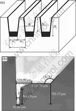
Fig.1 Shape of micro channel pattern and fabricated cutting tool: (a) Shape of micro channel pattern; (b) Single crystal diamond (w=80 ��m, ��=5.5?)
Fig.1(b) shows the main dimensions of fabricated cutting tool. The shape of pattern in trapezoid or rectangle is determined by shape angle of cutting tool. The material of tool is a single crystal diamond. The width of tool is 80 ��m, shape angle is 5.5? and relief angle is 3?. The effective length of the cutting tool is approximately 700 ��m. Table 1 lists the specification of fabricated cutting tool. And its dimension is applied to the cantilever simulation model for FEM analysis of cutting tool.
Table 1 Specification of fabricated cutting tool
1.2 Tool deflection due to machining in micro channel pattern
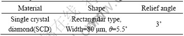
Tool deflection affects the limitation of machining characteristics on precision manufacturing due to a kind of vibration. The instability process occurs because the machining tool deflection is a abnormal cutting process that has influence on surface roughness and dimensional accuracy of workpiece, tool life and machine life[6-7]. Tool deflection related to vibration has been investigated in several studies for predicting the limit of stability on machining. The regenerative chatter is common in case of practical machining operation. Fig.2(a) shows the regeneration process that brings a kind of chatter on orthogonal metal cutting. In Fig.2(b), the relative displacement between workpiece and cutting tool generates deflection and vibration due to the interaction of cutting force that changes dynamic stiffness between two objects. The stability of cutting tool depends upon the interaction between the dynamic characteristics of the structure and the dynamic characteristics of the cutting process[6, 8]. In practical machining, the cutting force is fluctuated around an average value and relative deflection occurs between tool and workpiece[9]. The frequency of regenerative chatter is generated around the natural frequency of the machining system. The generative chatter has been generally analyzed with 1-D model of radial direction. However, the cutting tool with the feature of high aspect ratio has the lowest stiffness at the end part of tool tip[10]. Therefore, the serious weakness of dynamic stiffness characteristics in Y-axis of cutting direction in the cutting tool of the trapezoid or rectangular type that has the narrow width and sharp shape angle with high aspect ratio must be considered.
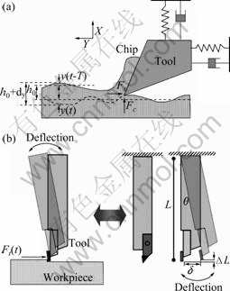
Fig.2 Generative process (a) and tool deflection on machining channel pattern (b)
The principal cutting force of Y-axis direction can be expressed as
![]() (1)
(1)
where ae is the effective width of cutter, Ks is the cutting force constant and Kr is the cutting force ratio.
Fig.2(b) shows that the relative displacement between cutting tool and workpiece produces the tool deflection of Y-axis direction in practical cutting process. It is assumed that the tool holder is rigidly supported by the tool without the deflection of machine and workpiece. And the cutting tool can be modeled as a solid cantilever beam with concentrated load at the end part of it.
1.3 FEM simulation of tool deflection
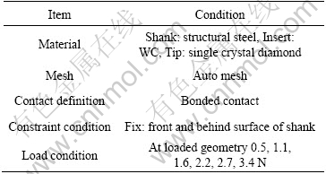
The FEM simulation of tool deflection simulation was carried out using the measured cutting force in case of practical machining. Table 2 shows the cutting conditions of FEM simulation. The cutting tool consists of shank, insert and tip. The contact conditions between parts of cutting tool are applied to be bonded with each other. The each part is automatically meshed. On constraint condition, the front and back surfaces of shank are fixed in all directions. Fig.3 shows the simulation modeling and simulation results of tool deflection by FEM. The total deflection of cutting tool is linearly increased by increasing cutting depth and most of tool deflections are observed at the end part of tip. In Fig.3(b), under cutting depth of 10 ��m, the total deflection of tool is 320 nm. In Fig.3(c), under condition of cutting depth of 20 ��m, the total deflection of tool is 590 nm. In Fig.3(d), under condition of cutting depth of 30 ��m, the total deflection of tool is 870 nm. This represents that the simplified cantilever model is very effective for predicting deflection of cutting tool. Later, additional simulation is needed to confirm the tool deflection under condition that tool relief angle, detailed contact condition and optimized mesh are considered.
Fig.3 Simulation results of different cutting depths and total deflections of cutting tools: (a) Simulation modeling of tool deflection; (b) 10 ��m, 320 nm; (c) 20 ��m, 590 nm; (d) 20 ��m, 870 nm
Table 2 Simulation conditions of tool deflection
2 Experimental setup
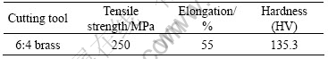
The machining system has three axes of driving system such as X-, Y- and Z-axis. Machining system is controlled by PMAC operation software. The air static pressure bearing in driving system can give the ability for the working table to be moved in X- and Y-axis with 5 nm of accuracy. Z-axis guide driven by linear motor has the positioning repeatability of 40 nm. Each cutting force of three axes can be measured in real time by dynamometer that is attached on the Z-axis. Fundamental machining experiment is carried out by shaping process with single crystal diamond with keeping increased cutting depth by 5 ��m. If the pattern pitch is 150 ��m, the line number of each cutting depth is 10. Table 3 shows the specification of fundamental machining conditions. The material of workpiece is 6?4 brass. Table 4 shows the properties of 6?4 brass workpiece. After machining experiment, cutting force, machined surface and burr formation are measured and analyzed for studying the influence of tool deflection with increased cutting depth on machining.
Table 3 Machining conditions of micro channel pattern
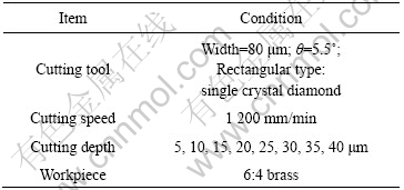
Table 4 Properties of 6?4 brass workpiece
3 Results and discussion
3.1 Cutting force analysis
The cutting forces and dynamic variation of cutting force in each axis are shown in Fig.4. When the cutting depth is increased, cutting force is increased with increasing dynamic variation of cutting force. In Fig.4(a), under cutting depth of 10 ��m, the principle cutting force (Fy) is 1.1 N. In Fig.4(b), under condition of cutting depth of 20 ��m, the cutting force is approximately 2.2 N. In Fig.4(c), under condition of cutting depth of 30 ��m, the cutting force is approximately 3.4 N. The tool deflection due to the relative weak stiffness of cutting tool is varied by the parameters such as rake angle, clearance angle and instantaneous cutting direction, which influence the cutting force. The dynamic variation of cutting force is determined by considering the total force at any point during the motion of cutting tool, corresponding to the instantaneous values of the cutting depth, rake angle and clearance angle, as shown in Fig.5[11-12].
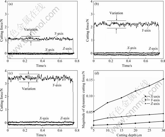
Fig.4 Results of cutting force at different cutting depths of 10 ��m (a), 20 ��m (b), 30 ��m (c) and dynamic variation of cutting force (d)
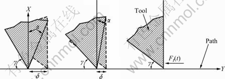
Fig.5 Variation of rake angle (��) and clearance angle (��) in machining process
The dynamic variation of cutting force that represents the tool deflection is increased with increasing cutting depth and its tendency is distinct in Y-axis direction with principle cutting force.
3.2 Machined surface analysis
The quality of the machined surface is mainly determined by the relative motion between the cutting tool edge and the workpiece. In practice, the tool path is deviated from the ideal tool path because the result of kinematic or dynamic factors due to the fact that the cutting process causes the motion errors and environmental disturbances of machining system. Fig.6 shows the results of machined surface. The burr formation of edge position on machined surface is proportional to cutting depth and its tendency is distinct above 20 ��m in cutting depth. Its height has fluctuating values due to influence of tool deflection like the result of cutting force. The surface roughness values of bottom position are increased with increasing cutting depth, as shown Fig.7. In Fig.7(a), under cutting depth of 10 ��m. surface roughness (Ra) is 2.0 nm and Rz is 28 nm. In Fig.8(b), under cutting depth of 20 ��m, Ra is 2.4 nm and Rz is 30 nm. In Fig.7(c), under cutting depth of 30 ��m, Ra is 2.8 nm and Rz is 36 nm. Most of measured results show that the machined surface in micro channel pattern is affected by the tool deflection caused by the parameters such as rake angle, clearance angle and cutting direction. With the fundamental machining results, the mold with various aspect ratio is fabricated. In Fig.8, the results of machined surface with increasing aspect ratio are obtained by step-by-step method with the cutting depth of 10 ��m on machining of micro channel pattern. As a whole, burr formation of edge position on fabricated channel pattern is increased with increasing aspect ratio. With increasing aspect ratio, deformation of entrance position represents the influence of tool deflection, as shown in Fig.8(c).
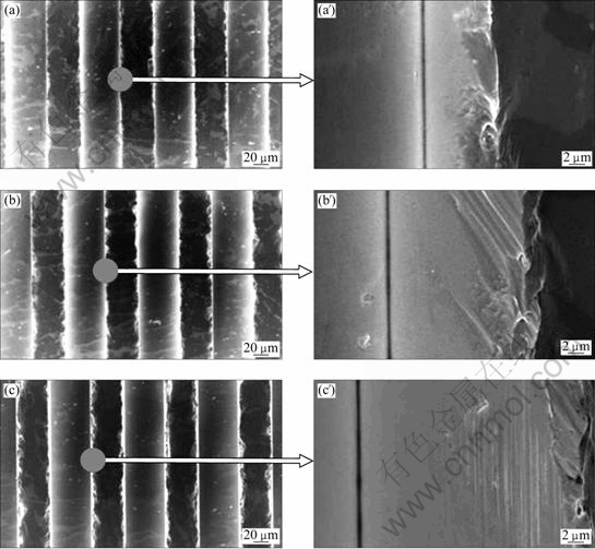
Fig.6 Results of machined surface and burr formation on machining channel pattern at different cutting depths: (a, a��) 10 ��m; (b, b��) 20 ��m; (c, c��) 30 ��m
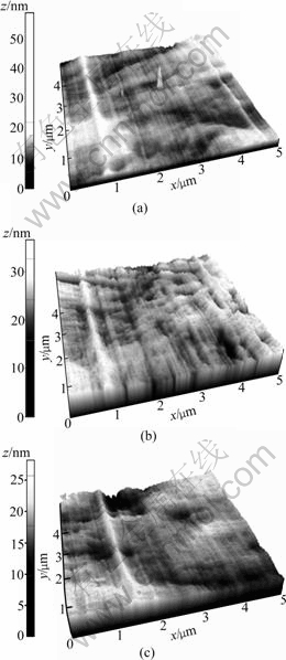
Fig.7 Results of surface roughness on bottom position of machining channel pattern: (a) Ra=2.0 nm, Rz=28 nm, cutting depth 10 ��m; (b) Ra=2.4 nm, Rz=30 nm, cutting depth 20 ��m; (c) Ra=2.8 nm, Rz=36 nm, cutting depth 30 ��m
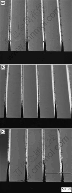
Fig.8 Results of machined surface with increment of aspect ratio on machining micro channel pattern: (a) h 50 ��m, pitch: 95 ��m; (b) h 75 ��m, pitch: 95 ��m; (c) h 100 ��m, pitch: 95 ��m
4 Conclusions
1) The influence of tool deflection on machined surface is experimentally verified by machining of micro channel pattern by using orthogonal cutting process and the analysis of tool deflection is performed using cantilever beam model.
2) The results of FEM simulation represent that tool deflection is linearly increased with increasing cutting depth and most of tool deflections are observed at the end part of tip.
3) On measured cutting force, the influence of tool deflection is observed through the results of increasing dynamic variation of cutting force with increasing cutting
depth.
4) On machined surface, the influence of tool deflection is observed through the results of increased surface roughness of Ra and Rz with increasing cutting depth.
5) Burr formation on edge position of machined surface is increased in proportional to increasing of cutting depth. And its height has fluctuating values like the result of cutting force due to tool deflection.
6) With the results of fundamental machining, the pattern mold with various aspect ratio is fabricated.
References
[1] LEE D. Topics of BLU & optical films for BLU [C]// Display Industrial Forum. Korea: Displaybank, 2007.
[2] IDE F, The optical films for flat panel display [M]. Japan: CMC Publisher, ISBN4-88231-430-4, C3054, 2004.
[3] JE T J, LEE K W and PARK S C. Machining technology of micro channel structure with high aspect ratio using shaping process [C]//International Conference on Micromanufacturing Conference, Pittsburgh: Carnegie Mellon University, 2008.
[4] LEE J W, KIM B D. Effects analysis for cutting depth on micro channel pattern machining [C]// Proceeding of the Journal of the Korean Society of Manufacturing Process Engineers Spring Annual Meeting. Jeju, 2008.
[5] KIM B D, LEE K W. High aspect ratio micro channel pattern machining using shaping process [C]// Proceeding of the Journal of the Korean Society of Manufacturing Process Engineers Spring Annual Meeting. Jeju, 2008.
[6] SWEENEY G, TOBIAS S A. Survey of basic machine tool chatter research [J]. International Journal of Machined Tool Design and Research, 1969, 9: 217-238.
[7] KOVACIC I. The chatter vibrations in metal cutting-theoretical approach [J]. The Scientific Journal of FACTA UNIVERSITATIS, 1998, 1(5): 581-593.
[8] EL-BADAWY A A, EL-DEEN T N N. Closed-loop feedback model of chatter in a shaping operation [C]// ECCOMA S. Thematic Conference on Computational Methods in Structural Dynamics and Earthquake Engineering. Greece, 2007.
[9] TOBIAS S A. Machine tool vibration research [J]. International Journal of Machined Tool Design and Research, 1961, 1: 1-14.
[10] DUGAS A, LEE J J, HASCOET J Y. An enhanced machining simulator with tool deflection error analysis [J]. Journal of Manufacturing System, 2002, 21(6): 451-463.
[11] KNIGHT W A. Chatter in turning: Some effects of tool geometry and cutting conditions [J]. International Journal of Machined Tool Design and Research, 1972, 12: 201-220.
[12] GANGULI A, DERAEMAEKER A, HORODINCA M, PREUMONT A. Active damping of chatter in machine tools- demonstration with a ��Hardware in Loop�� simulation [C]// Proceedings of the Institution of Mechanical Engineerings, 2005, 219(5): 359-369.
Corresponding author: Tae-Jin JE; Tel: +82-42-868-7142; E-mail: jtj@kimm.re.kr
(Edited by LI Xiang-qun)
